
Abstract
This work studied the effect of the dewatering conditions on the behavior of fiber foams during dewatering and on the final structure of the formed, thick, lightweight lignocellulosic materials. The vacuum level, fiber type, consistency, and basis weight of the fiber foam were all varied. During dewatering, the time evolution of the thickness of the fiber foam in the mold was studied, and the dryness of the fiber foam immediately after dewatering was measured. The density and pore size profiles of the final dry materials was measured using X-ray microtomography (µCT).
Download PDF
Full Article
Dewatering and Structural Analysis of Foam-Formed, Lightweight Fibrous Materials
Janne T. Keränen,* Petri Jetsu, Tuomas Turpeinen, and Antti I. Koponen
This work studied the effect of the dewatering conditions on the behavior of fiber foams during dewatering and on the final structure of the formed, thick, lightweight lignocellulosic materials. The vacuum level, fiber type, consistency, and basis weight of the fiber foam were all varied. During dewatering, the time evolution of the thickness of the fiber foam in the mold was studied, and the dryness of the fiber foam immediately after dewatering was measured. The density and pore size profiles of the final dry materials was measured using X-ray microtomography (µCT).
DOI: 10.15376/biores.18.1.531-549
Zenodo open data: https://zenodo.org/record/6445587
Keywords: Foam forming; Foam formed materials; Dewatering of foam; X-ray microtomography
Contact information: VTT Technical Research Centre of Finland Ltd, Koivurannantie 1, 40400 Jyväskylä, Finland, *Corresponding author: janne.keranen@vtt.fi
GRAPHICAL ABSTRACT
INTRODUCTION
The goal of the 2015 Paris Climate Change Agreement is to limit global warming to 1.5 °C. To reach this goal, climate neutrality must be achieved by mid-century (Paris Agreement 2015). One possible solution to reduce carbon emissions in the future is to develop zero-carbon or even carbon-negative products. Such products could be used in many industry sectors, such as packaging, construction, automotive, and transportation. Wood is an abundant, renewable, carbon-holding material. Therefore, wood-based products offer natural alternatives to support the achievement of the set climate change goals.
Foam forming (Smith et al. 1974; Smith and Punton 1975; Lehmonen et al. 2020; Hjelt et al. 2021) is a forming technology that enables the manufacturing of sustainable, highly porous, and lightweight products from lignocellulosic fibers. In the foam forming process, fibers, water, and a foaming agent are mechanically mixed under high shear to form a fiber foam with an air content of 50% to 70%. After the foam generation phase, the fiber foam is spread on a wire mesh (wire), and most of the water is removed by gravity or moderate vacuum through the wire. Mechanical pressure or high vacuum levels cannot be used, as they would severely compress the material. Finally, the material is dried by non-contact thermal drying methods to maintain the high porosity (Timofeev et al. 2016; Timofeev et al. 2022). The result is a lightweight lignocellulosic fibrous material (LLFM), the density of which can be as low as 10 kg/m3. The mechanical properties of LLFMs have been studied in recent years (Alimadadi and Uesaka 2016; Ketoja et al. 2019). If needed, LLFMs can be reinforced by adding fibrils, fines, cellulose nanofibrils, or polymers to the structure (Cervin et al. 2013; Korehei et al. 2016; Li et al. 2016; Pöhler et al. 2020). Lightweight lignocellulosic fibrous material can be used for thermal insulation (Pöhler et al. 2017; Lecourt et al. 2018), sound insulation (Pöhler et al. 2016; Nechita and Năstac 2018), packaging (Ottenhall et al. 2018), or internal decoration (Härkäsalmi et al. 2017; Siljander et al. 2019).
Good knowledge of the dewatering kinetics of fiber foams and the ensuing structure (e.g., density and pore size profiles) is essential for designing profitable real-life processes. Water removal during dewatering should be maximized to minimize the energy consumption during thermal drying, which is an expensive way to remove moisture. There should also be good control of the properties of the final product to ensure its suitability for the aimed purpose, such as the insulation of heat or the damping of sound. Good structural control also allows for the development of materials for novel uses and products.
There are only a few published studies on the dewatering of fiber foams. Moreover, in some cases, the vacuum levels are too high and the basis weight (BW) is too low to produce LLFMs (Lehmonen et al. 2020). Several studies have investigated the dewatering of fiber foams under gravity (Mira et al. 2014; Li et al. 2016; Haffner et al. 2017). They found that the presence of cellulosic fibers slowed down the dewatering process considerably when compared to pure foams. Koponen et al. (2020) studied the effect of the vacuum level (0 kPa to 5 kPa) on the dewatering process and the final dryness of the fiber foam. With 0 kPa of vacuum, the sample shrinkage was approximately equal to the volume of the drained water. When the vacuum level was increased to 0.5 kPa, the dryness of the 1,600 kg/m3 bleached softwood kraft pulp (BSKP) sample increased from 8% to 13%, with a negligible effect on the sample shrinkage. At 5 kPa, the vacuum dryness was 22%, but the final sample volume was also 33% smaller. More research is needed for the optimization of the vacuum-based dewatering phase to save time and energy during the thermal drying of LLFMs.
The structure of the final dry LLFMs has been studied in a few papers. Madani et al. (2014) and Korehei et al. (2016) used a 10 kPa vacuum for water removal. Madani et al. (2014) studied the effect of air content (30 vol.% to 50 vol.%) and fiber length (1.8 to 3.3 mm) on the structural properties with a fiber consistency of 0.5%, where consistency is the mass fraction of solids in the suspension. The obtained sample densities varied between 8 and 35 kg/m3, and the density decreased as the air content and fiber length increased. When varying the initial fiber consistency from 0.5% to 2.0%, Korehei et al. (2016) obtained sample densities from 14 to 139 kg/m3. Lecourt et al. (2018) studied the structure of materials made with either gravity or a moderate vacuum. They found that at the bottom side a denser layer of fibers (‘skin’) had developed. The skin was much denser at the bottom when a vacuum was used. At the top side of the sample, the density was also clearly above the average density of the material. Burke et al. (2019) observed similar structures in samples that were made without a vacuum. They also studied the effect of fiber concentration (1% to 5%) and air content (50 vol.% to 75 vol.%) on the sample density. The densities ranged between 10 and 45 kg/m3, and the density decreased both with increasing air content and decreasing fiber consistency. Burke at al. (2021) made samples from BSKPs with gravity and used X-ray microtomography (µCT) for a detailed analysis of the obtained structures. The average pore size was 0.6 mm for both air contents (50 vol.% and 75 vol.%). The fibers were aligned mainly in planes perpendicular to the direction of dewatering. With the higher liquid fraction, more fibers were aligned in the direction of gravity. Currently, there are no works in which the internal structure of the LLFMs has been studied systematically with variable dewatering conditions.
The goal of this work was to gain a deeper understanding of the effect of the dewatering conditions on the behavior of the fiber foams during dewatering, and on the final structure of the formed LLFMs. The dewatering conditions were altered by varying the vacuum level, fiber type, consistency, and BW of the fiber foam. During dewatering, the time evolution of the thickness of the fiber foam in the mold was studied, and the dryness of the fiber foam was measured immediately after dewatering. The density and pore size profiles of the final dry materials were also measured with µCT.
EXPERIMENTAL
Materials
Unrefined BSKP from Metsä Fibre (Äänekoski, Finland) and bleached chemi-thermomechanical pulp (CTMP) from Rottneros (Rottneros, Sweden) were used in the experiments. The pulps chosen were commercially available qualities. Metsä BSKP (Metsä pine AKI) was made from pine and spruce with mass fractions of 50-80% and 20-50%, respectively. CTMP was made purely from spruce. The pulp properties can be seen in Table 1. The Schopper Riegler (SR) and Canadian standard freeness (CSF) values were determined according to the ISO 5267-1 (2000) and ISO 5267-2 (2001) standards, respectively. The conversions between the CSF and SR values were performed using the AFT freeness conversion chart (AFT 2018). The fines content was determined using an L&W fiber tester plus (ABB AB/Lorentzen & Wettre, Kista, Sweden).
Table 1. The Properties of the BSKP and CTMP Fibers

The foaming agent was a mixture of two surfactants: sodium dodecyl sulfate (SDS) and polysorbate 20 (Tween20). The SDS and Tween20 were dosed at 0.48 g/L and 0.51 g/L, respectively. By using a co-surfactant with the SDS, the foaming agent residue in the foam-formed materials can be minimized (Viitala et al. 2020).
Fiber foam generation
Figure 1a shows the experimental set-up used for the preparation of the fiber foams. The set-up consisted of a transparent vessel with a volume of either 8.8 or 13 L (Ø 160 or 193 mm) and a mechanical mixer (power of 1.5 kW) fitted with a disk-type stirrer. The disk (Ø 83 mm) had two opposing 25-degree bends, with their fulcrum positioned 25 mm from the center. To perform the foaming procedure, the fiber suspension (initial volume of 1.2 to 4.9 L, depending on the target consistency of the pulp and the BW of the sample) was first added to the vessel. Then, surfactants were dosed to the fiber suspension and mixing was started. The target air content of the fiber foam was 60 vol.%, and the mixing speed (3,800 revolutions per minute (rpm) to 4,900 rpm) and mixing time (2.5 min to 10 min) were adjusted accordingly at each trial point. Forming consistencies of 2.5%, 5%, and 8% were used for the pulps in the experiments. The required mixing speed and time to achieve the target air content increased with the increasing consistency. The average foam bubble diameter was ca. 100 μm (Mira et al. 2014; Koponen et al. 2020)
Sample preparation
The utilized handsheet mold consisted of a funnel, an upper container, a wire (Valmet Forming Fabric GM, thread count 108-140) and its supports, and a lower container (Fig. 1b). The generated fiber foam was poured into the upper container (on the wire) with the help of the funnel. After the foam was settled, it was dewatered through the wire with the help of a vacuum (0 to 8 kPa). The retention was close to 100%. Mainly water, but also wet foam, flowed into the lower container, and a handsheet (220 mm × 350 mm) was formed on the wire. The dewatering time was always 15 minutes. The wet sheet that formed on the wire was removed from the mold and two 220 mm × 20 mm samples were cut from both the ends of the sheet to measure the dry solids content/dryness (DSC). The remaining sheet was dried in a convection oven at 70 °C overnight. After drying, the sheet edges were trimmed with a bandsaw. Examples of the appearance of the final dry BSKP samples are presented in Fig. 2.

Fig. 1. a) Experimental set-up for the preparation of the fiber foams and b) foam forming sheet mold

Fig. 2. Dry BSKP samples after trimming at forming consistencies of a) 2.5%, b) 5%, and c) 8%
Measurements
The thickness of the fiber foam in the mold was recorded during dewatering as a function of time by a laser system that consisted of a laser sensor and a data acquisition system (Fig. 3a). The DSC of the final sample was measured after dewatering, according to the ISO 638 (2008) standard. The thickness of the dry sample was measured using a laser sensor equipped with a digital display unit (Fig. 3b). The samples were also weighed to determine the BW and average density of the formed materials. Basis weight was determined according to SFS-EN ISO 536:2012.

Fig. 3. The laser systems for measuring the a) sample thickness during dewatering and b) thick-ness of a dry sample
X-ray microtomography
X-ray microtomography produces a three-dimensional (3D) volume image of the fine scale structure of the sample. The output of the imaging process is a volume image where contrast originates from differences in local X-ray attenuation in the sample, which correlates with the local material density. The obtained 3D X-ray attenuation maps can be binarized into void (air) and fiber phases by choosing a suitable threshold value. In this work, µCT images were obtained by Rx-solutions Desktom 130 tomograph (Chavanod, France), which had a maximal resolution/minimal voxel size (size of the smallest detail distinguishable in the image) of 4 µm.
In X-ray tomographic imaging, one needs to find a compromise between maximizing the sample size and minimizing the voxel size. In this work, the size of the imaged samples was 1.5 cm × 1.5 cm × height, and the voxel size was 27 µm. (The sample height varied depending on the process parameters, see Table 2). The obtained structure may depend on the used resolution. In Lecourt et al. (2018), the fiber volume fraction calculated from the µCT images was four times higher than the real value when measured at a resolution of 9 µm. In this study, one sample was imaged with resolutions of 9, 20, and 30 µm. It was found that the average pore diameter was similar for all three resolutions, but the fiber volume fraction of the binarized images varied between 6% and 15%. For this reason, the fiber volume fraction calculated from the µCT images is referred to below as “nominal”. As shown below in Fig. 6 and Eqs. 2 and 3, the nominal fiber volume fraction (NFVF) could be transformed to real fiber density with two pulp-specific calibration curves.
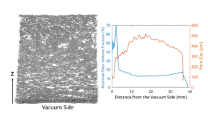
An example of a µCT image of a formed and dried sample is shown in Fig. 4a. For structural analysis, the top and bottom surfaces of the images were determined using the method described in Turpeinen et al. (2015). This allowed for calculating the z-directional NFVF profiles (ε(z)) for the binarized tomographic images (Fig. 4b). In this case, the NFVF was approximately 14 times higher than the real fiber volume fraction calculated from the density of the dry sample. Binarizing the tomographic images to the real fiber volume fraction led to images where the fiber structure was not clearly seen.

Fig. 4. a) Example of a tomographic image of a formed and dried sample. A thin slice in the middle of the sample is shown. The b) NFVF as a function of distance z from the vacuum side (the bottom of the sample). A denser layer (‘skin’), with a thickness of approximately 3 mm, developed on the vacuum side during forming. (Trial point 2 in Table 2: BSKP furnish, vacuum 0.5 kPa, density of dry sample 19 kg/m3)

Fig. 5. The pore size distribution for the sample shown in Fig. 4a. The average pore size was 464 µm
In the NFVF profile, there was always a denser region (‘skin’) at the vacuum side (Fig. 4a). The thickness of the skin was estimated using Eq. 1,
 (1)
(1)
where α, β, γ, and δ are fitting parameters to the points right from the peak value, as can be seen in the red curve in Fig. 4b. The skin thickness was defined as the distance between the half-width point and the bottom (z = 0).
Figure 4a shows that the structure was not completely homogeneous. There were many large voids, which were due to non-optimal dispersion of the fibers and merging of foam bubbles and fibers during forming and drying (Burke et al. 2021). The pore size distribution was estimated by using the method described in Hildebrand and Rüesgsegger (1997). In effect, maximum-sized spheres were fit into the void space that did not include the fiber phase. As an outcome, each voxel in the 3D space of the image was labeled with the diameter of the maximal sphere it belonged to. To measure the mean pore diameter, the fitted sphere diameter values were integrated over the void space and divided with the total void volume. Similarly, the mean pore size at each z-position could be determined; Fig. 5 shows the pore size distribution for the sample shown in Fig. 4a.

Fig. 6. The average sample density as a function of average nominal fiber volume fraction of X-ray tomographic images. The straight lines are calibration curves that can be used for calculating the real local density from the nominal fiber volume fraction.
Figure 6 shows the average sample density as a function of average NFVF of the µCT images. There was a linear correlation between the two quantities, which was slightly different for the BSKP and the CTMP – CTMP had generally slightly higher density with a given NFVF. The solid lines for the BSKP and CTMP are calibration curves represented by Eqs. 2 and 3, respectively,
 (2)
(2)
 (3)
(3)
Eqs. 2 and 3 can be used to calculate the real local density and the maximum density of the skin from the NFVF.
Trial setup
An overview of the trial setup for the study can be seen in Table 2. The parameters included the pulp type (BSKP or CTMP), forming consistency (c), dewatering vacuum level (P), BW, DSC, final height after drying (h), density of the dry sample (ρ), thickness of the dry sample skin (S), maximum density of the skin (ρmax), average pore size (D), and maximum of NFVF (εmax). The target BW values were 800 g/m2 or 1,600 g/m2.
Table 2. Trial Setup for the Study

RESULTS AND DISCUSSION
Time Evolution of Dewatering
Figures 7 and 8 show the thickness of the fiber foam in the mold during dewatering as a function of time for the BSKP and CTMP, respectively, for the consistencies of 2.5% and 5% and vacuum levels of 0.5, 2, and 4 kPa. There was some variation in the initial thickness, and it has been scaled in Figs. 7 and 8 to either 70 mm (for 2.5%) or 35 mm (for 5%) to make the interpretation of the figures easier. Koponen et al. (2020) studied the effect of vacuum level on the thickness of foam formed samples during dewatering. It was found that the sample volume always decreased, at least the volume of the drained water. Moreover, as the vacuum increased, there was an increasing loss of volume due to the plastic compression of the structure. In BSKP, for the vacuum levels of 0.5 kPa, 2 kPa, and 4 kPa, the volume losses due to the removal of water were 25 vol.%, 26 vol.%, and 27 vol.%, respectively, and the volume losses due to plastic compression were 3 vol.%, 8 vol.%, and 17 vol.%, respectively. Therefore, during water removal, the decrease of the thickness seen in Figs. 7 and 8 was mainly due to water being removed from the sample. However, the thickness also decreased due to plastic compression, the effect being stronger with higher vacuum levels. In the beginning of the dewatering process, the surface level dropped abruptly (an amount of ) during the first few seconds (denoted as td). The drop usually increased as the vacuum level increased. The reason for this is currently unknown. Generally, at a given time, the foam thickness was lower for the BSKP, and it decreased for both pulps with the increasing vacuum levels. The effect of the vacuum on the thickness was smaller for the higher consistency, as there was much less free water to remove.
The surface level curves were not smooth enough for a detailed analysis of time evolution of the dewatering rate. To examine the general behavior, Eq. 4 was fit (Koponen et al. 2020),
 (4)
(4)
to the (t, z) data points after the abrupt drop (t ≥ td). Here, z is the surface height, z0 is the height at t = td, zΔ is the total height change during dewatering, and T is the time scale of the whole dewatering process. Figures 7 and 8 show two examples of the fitted curves. It was found that T was, on average, two times higher for the CTMP.

Fig. 7. Time evolution of the thickness of the fiber foam in the mold for the BSKP during dewatering with consistencies of 2.5% and 5% and vacuum levels of 0.5, 2, and 4 kPa. The solid black line is a fit of Eq. 4 to the measurement data.

Fig. 8. Time evolution of the thickness of the fiber foam in the mold for the CTMP during dewatering with consistencies of 2.5% and 5% and vacuum levels of 0.5, 2, and 4 kPa. The solid black line is a fit of Eq. 4 to the measurement data.
The average dewatering rate during the first 100 s after the initial drop was also examined. During this period, the dewatering rates were rather similar with different vacuum levels. Therefore, the effect of the vacuum became more pronounced in the later phase of the dewatering process. The dewatering rates during the first 100 s (average over the three vacuum levels) were 0.12, 0.051, 0.083, and 0.030 kg/m2s for the BSKP-2.5%, BSKP-5%, CTMP-2.5%, and CTMP-5% samples, respectively. The initial dewatering rate was 50% higher for the BSKP. For both pulps, the initial dewatering rate was 250% higher for the lower consistency. The dewatering rate of CTMP-5% was 50% higher than what was observed by Koponen et al. (2020), where no vacuum was used.
Dryness after dewatering
The dryness after dewatering is shown for all trial points as a function of vacuum in Fig. 9. As can be seen in Fig. 9, the dryness for both pulps increased as the vacuum level increased, and the dependence of the dryness on the vacuum level was approximately linear. The dryness usually increased as the consistency increased, as there was then less water to be removed from the structure. For the BSKP, the dryness was slightly lower at a higher BW. The BSKP always had a noticeably higher dryness than the CTMP. This is explained with the water retention value of the BSKP, which was 30% lower than the CTMP, and the freeness of BSKP, which was 17% higher than the CTMP. These properties were due to the fines content being clearly higher for the CTMP. It was possible to get a high dryness, 30% and 18%, for the BSKP and CTMP, respectively, with a vacuum of 8 kPa. However, the thickness of the structure reduced considerably at this vacuum level, as seen in Table 2 and Fig. 10.
A linear regression analysis was performed in which the dependent variable was the dryness after forming (DSC). The forming consistency (c) and vacuum (P) were the independent variables. To be able to compare the pulps, the BW was dropped from the model and higher BW points were omitted for the BSKP. The linear regression formula can be described by Eq. 5,
 (5)
(5)
where α, β, and γ are the regression coefficients. Table 3 shows the obtained model parameters for the BSKP and CTMP. For clarity, the Table 3 also shows the independent variables and the units of the variables. The regression model worked quite well, which was reflected by a rather high coefficient of determination (R2). As seen in Table 3 (coefficient γ) and Fig. 9, the dryness of the BSKP increased almost twice as much with an increase of the vacuum level.

Fig. 9. Dryness after forming as a function of the vacuum level at target BWs of a) 800 kg/m2 and b) 1,600 kg/m2. Some values are averages over trial points with identical process parameters.
Table 3. Regression Coefficients of Linear Regression Analysis for Dryness

Density of dry sample
Figure 10 shows the density of the final dry sample as a function of the vacuum level. The density was generally higher for the BSKP, which may have been due to the higher slenderness of the BSKP fibers. For both pulps, the density clearly increased with increasing consistency. Especially at a forming consistency of 2.5%, the density was constant up to 2 kPa vacuum, after which it increased strongly with increasing vacuum.

Fig. 10. The density of the final dry sample as a function of the vacuum level at target BWs of 800 kg/m2 and 1,600 kg/m2. Some values are averages over trial points with identical process parameters.
A linear regression analysis was performed, where the dependent variable was the density of a dry sample (ρ). The forming consistency (c) and vacuum (P) were the independent variables. In the analysis, those trial points were included, where the target BW was 800 kg/m3. The linear regression formula for the density was calculated using Eq. 6,
 (6)
(6)
where α, β, and γ are the regression coefficients. In Eq. 6, a quadratic term (γ × P2 ) was used instead of a linear term (γ × P), as the quadratic term gave higher R2 values than the linear term. Table 4 shows the obtained model parameters for both pulps. The regression model worked quite well, which was reflected by very high R2 values. As seen by the γ value in Table 4, the density of the BSKP increased 50% more as the vacuum level increased. For clarity Table 4 also shows the independent variables and the units of the variables.
Table 4. The Regression Coefficients of the Linear Regression Analysis for Density (Eq. 6)

Z-directional NFVF
Figure 11 shows the NFVF at a BW of 800 kg/m3 and a consistency of 2.5% as a function of distance z from the vacuum side (sample bottom). The vacuum levels of 0.5 and 1 kPa were omitted from Fig. 11, as their profiles were similar to the vacuum levels of 0 and 2 kPa. With vacuum levels 0 to 2 kPa, the skin region was narrow and sharp, and its thickness was approximately 10% of the whole sample. With 4 kPa, the skin was somewhat wider; its thickness was about 20% of the whole sample, and the NFVF decreased smoothly after the peak value. With 8 kPa, the sample compressed strongly and the NFVF decreased smoothly after the peak value up to the top side of the sample. Figure 12 shows the NFVF profile at a BW of 800 kg/m3 and consistency of 5%. In the skin region, the profiles were rather similar to the 2.5% profiles.

Fig. 11. NFVF for the a) BSKP and b) CTMP as a function of distance z from the vacuum side. The forming consistency was 2.5% and the target BW was 800 kg/m2.

Fig. 12. NFVF for the a) BSKP and b) CTMP as a function of distance z from the vacuum side. The forming consistency was 5% and the target BW was 800 kg/m2.
The thickness of the skin is shown in Fig. 13a as a function of the vacuum level for the BW of 800 kg/m3 and for both forming consistencies. The skin thickness was approximately constant with lower vacuum levels. The forming consistency had no systematic effect on the skin thickness. Figure 13b shows the maximum fiber density, which was calculated with the calibration curves from Eqs. 2 and 3. Figure 13b shows that maximum fiber density generally increased with the increasing vacuum level, being approximately 30% to 50% higher with 8 kPa of vacuum compared to 0 kPa of vacuum. The maximum fiber density was slightly higher for the BSKP, with vacuum levels of 0 to 2 kPa, likely due to the higher slenderness of the BSKP fibers. Notice that the forming of skin shares some similarities with the sheet sealing effect seen in paper machines (Hubbe et al. 2020), although the time scales and vacuum levels are different. Sheet sealing is a complex process due to viscoelasticity of the fiber network and due to the relation between the network density and its flow resistivity to water/foam being non-linear. The non-linearity of the drainage process and the initially random distribution of fibers and flocs can lead to spatial variations of the skin thickness (an example of this this is seen in Fig. 4a). This, together with the small sample size, explains the variation of the maximum fiber density shown in Fig. 13b.

Fig. 13. a) Skin thickness as a function of the vacuum level and the b) highest fiber density in the skin as a function of the vacuum level for the 800 kg/m3 samples
Figure 14 shows the NFVF for the 1,600 kg/m3 samples. The profiles were very similar for 0.5 and 2 kPa of vacuum.

Fig. 14. NFVF for the 1,600 kg/m2 BSKP as a function of distance from the bottom side
At consistencies of 2.5% and 5%, the skin was only slightly thicker with 4 kPa, but with 8% consistency, it was clearly thicker with 4 kPa. For both BW levels, the NFVF profiles were U-shaped, more strongly so with the higher consistency and the higher BW. Similar behavior was also seen in Lecourt et al. (2018) at a BW of 800 kg/m3. Finally, a higher-density region was sometimes developed also at the top side. This was also seen in previous research (Madani et al. 2014; Lecourt et al. 2018; Burke et al. 2019).
Pore size
Figure 15 shows the average pore size as a function of the sample density. The pore size was approximately inversely related to the density. The CTMP generally had a higher pore size, but the difference decreased as the density increased. In a study by Burke et al. (2021) samples from BSKP pulp with gravity-driven water removal were produced. The density of the final samples was 13 kg/m3. The pore size was 600 µm, which is in line with the results from this study.

Fig. 15. Average pore size as a function of the sample density for the BSKP and CTMP. The two BSKP outliers marked with a red cross are for trial points 25 and 26, where big cavities developed in the internal structure.

Fig. 16. Pore size distribution for the a) BSKP and b) CTMP at a consistency of 2.5% and a BW of 800 g/m2. The local pore size of the CTMP at 0 kPa vacuum was exceptionally high at z = 5 mm (1,200 µm). At this region, the nominal fiber volume was also half of the average value (Fig. 11b).
The z-directional pore size distributions are shown for both pulps with the consistency of 2.5% and at a BW of 800 kg/m2 for different vacuum levels in Fig. 16. The profiles were qualitatively similar for both pulps. The 0 and 2 kPa profiles were relatively constant inside the sample. Only close to the bottom and top surfaces was the pore size clearly smaller. The 4 kPa pore size was mostly constant, but in the skin region, there was a region where the pore size decreased strongly and monotonously when going closer to the bottom side. The 8 kPa pore size decreased monotonously from the top side to the bottom side.
Discussion
In this paper the samples were dried in an oven. (Timofeev et al. 2016) studied thermal drying of lightweight fibrous materials with infrared heating in combination with vacuum and impingement drying (hot air jet). They found that drying could be significantly improved without compression of the material. Minimizing the shrinkage of the sample during drainage is thus critical for the successful manufacture of lightweight fibrous materials.
The target density depends on the application. For thermal insulation, the optimal density level is 40 to 70 kg/m3 (Pöhler et al. 2017), and a similar density range works well also for sound absorption (Nechita and Năstac 2018). The densities obtained with the current setup are rather low, especially so with the lower vacuum levels. However, higher vacuum levels create a thick skin layer on the vacuum side. If one wants a relatively high density with a minimal skin, low vacuum levels can be used for dewatering, and the sample can be gently pressed to the desired density level afterwards (Pöhler et al. 2017).
The formation of the skin is not always a liability; it could also be an asset. For heat insulation applications, a high-density surface layer is useful for increasing the air flow resistance (Pöhler et al. 2016). For sound absorption, a thin, dense surface layer can be utilized to shift the maximum sound absorption towards lower frequencies (Tiina Pöhler, unpublished data). In filtering materials, a density profile is often used to improve the filtering efficiency and to prolong the working life of the filter. In such filters, density increases when going from the upstream surface to the downstream surface. The biggest particles are then stopped close to the upstream surface and the smallest particles close to the downstream surface. This study shows that it is possible to create similar structures with fiber foams; one can get a density profile at the vacuum side, and its thickness can be controlled with the vacuum level and the fiber foam properties. However, with an increasing vacuum level, the whole structure also compresses more. It is possible that by using a time-dependent vacuum level, the properties of the density profile could be better controlled, simultaneously limiting the overall compression.
CONCLUSIONS
- This work investigated the effect of the dewatering conditions on the behavior of fiber foams during dewatering, as well as the final structure of the formed LLFMs.
- In both the BSKP and CTMP, the dryness increased as the vacuum level increased. The dependence of the dryness on the vacuum level was approximately linear, and the dryness usually increased as the consistency increased. The dryness of the BSKP at 8 kPa vacuum (30%) was clearly higher than that of the CTMP at the same vacuum (18%).
- With vacuum levels 0 to 4 kPa, the sample density varied between 20 and 35 kg/m3. At 8 kPa of vacuum, the highest densities for the BSKP and CTMP were obtained, at 40 and 60 kg/m3, respectively. The dependence of density on the vacuum level was quadratic for both pulps. The density was generally higher for BSKP. In both the BSKP and CTMP, the density clearly increased as the consistency increased.
- The average pore size for both pulps was inversely related to the density. At lower densities, the pore size was clearly higher for the CTMP pulp, but the difference decreased with increasing density. The lowest densities’ pore size was 600 to 800 µm, while the highest densities’ pore size was 200 µm.
- During water removal, a dense region (‘skin’) was created at the vacuum side. With low vacuum levels (0 to 2 kPa), this region was rather narrow and sharp, and the skin thickness was approximately constant, 2 mm. With higher vacuum levels a density profile (or a gradient structure) was formed. The maximum fiber density in the skin varied between 70 and 100 kg/m3 depending on the vacuum level.
- Future research on this topic may include using a time-dependent vacuum level, as it may better control the density profile properties of the fiber foam.
ACKNOWLEDGMENTS
This work was supported by the European Regional Development Fund under Grants A73092 and A75938 (Projects “Future Fibre Products” and “Piloting Alternatives for Plastics”).
REFERENCES CITED
AFT (2018). “Pulp freeness conversion chart,” AFT, (https://aft-global.com/en/resources/pulp-freeness-conversion-chart), Accessed 21.5.2022.
Alimadadi, M., and Uesaka, T. (2016). “3D-oriented fiber networks made by foam forming,” Cellulose 23(1), 661-671. DOI: 10.1007/s10570-015-0811-z
Burke, S. R., Möbius, M. E., Hjelt, T., and Hutzler, S. (2019). “Properties of lightweight fibrous structures made by a novel foam forming technique,” Cellulose 26(4), 2529-2539. DOI: 10.1007/s10570-018-2205-5
Burke, S. R., Möbius, M. E., Hjelt, T., Ketoja, J. A., and Hutzler, S. (2021). “Analysis of the foam-forming of non-woven lightweight fibrous materials using X-ray tomography,” SN Applied Sciences 3(2), 192. DOI: 10.1007/s42452-021-04172-9
Cervin, N. T., Andersson, L., Ng, J. B. S., Olin, P., Bergström, L., and Wågberg, L. (2013). “Lightweight and strong cellulose materials made from aqueous foams stabilized by nanofibrillated cellulose,” Biomacromolecules 14(2), 503-511. DOI: 10.1021/bm301755u
Haffner, B., Dunne, F. F., Burke, S. R., Hutzler, S. (2017). “Ageing of fibre-laden aqueous foams,” Cellulose 24(1), 231-239. DOI: 10.1007/s10570-016-1100-1
Härkäsalmi, T., Lehmonen, J., Itälä, J., Peralta, C., Siljander, S., and Ketoja, J. (2017). “Design-driven integrated development of technical and perceptual qualities in foam-formed cellulose fibre materials,” Cellulose 24(11), 5053-5068. DOI: 10.1007/s10570-017-1484-6
Hildebrand, T., and Rüesgsegger, P. (1997). “A new method for the model-independent assessment of thickness in three-dimensional images,” Journal of Microscopy 185(1), 67-75. DOI: 10.1046/j.1365-2818.1997.1340694.x
Hjelt, T., Ketoja, J. A., Kiiskinen, H., Koponen, A. I., and Pääkkönen, E. (2022). “Foam forming of fiber products: A review,” Journal of Dispersion Science and Technology 43(10), 1462-1497. DOI: 10.1080/01932691.2020.1869035
Hubbe, M., Sjöstrand, B., Nilsson, L., Koponen, A., and McDonald, J. D. (2020). “Rate-limiting mechanisms of water removal during the formation, vacuum dewatering, and wet-pressing of paper webs: A review, Bioresources 15(4), 9672-9755. DOI: 10.15376/biores.15.4.Hubbe
ISO 638 (2008). “Paper, board and pulps – Determination of dry matter content – Oven-drying method,” International Organization for Standardization, Geneva, Switzerland
ISO 5267-1 (2000). “Pulps – Determination of drainability – Part 1: Schopper-Riegler method,” International Standardization of Organization, Geneva, Switzerland.
ISO 5267-2 (2001). “Pulps – Determination of drainability – Part 2: “Canadian Standard” freeness method,” International Organization for Standardization, Geneva, Switzerland.
Ketoja, J. A., Paunonen, S., Jetsu, P., and Pääkkönen, E. (2019). “Compression strength mechanisms of low-density fibrous materials,” Materials 12(3), 384. DOI: 10.3390/ma12030384
Koponen, A. I., Timofeev, O., Jäsberg, A., and Kiiskinen, H. (2020). “Dewatering of high-consistency fiber-laden foams,” Cellulose 27(15), 9637-9652. DOI: 10.1007/s10570-020-03416-y
Korehei, R., Jahangiri, P., Nikbakht, A., Martinez, M., and Olson, J. (2016). “Effects of drying strategies and microfibrillated cellulose fiber content on the properties of foam-formed paper,” Journal of Wood Chemistry and Technology 36(4), 235-249. DOI: 10.1080/02773813.2015.1116012
Lecourt, M., Pöhler, T., Hornatowska, J., Salmén, L., and Jetsu, P. (2018). “Density profiles of novel kraft pulp and TMP based foam formed thermal insulation materials observed by X-ray tomography and densitometry,” Holzforschung 72(5), 397-403. DOI: 10.1515/hf-2017-0116
Lehmonen, J., Retulainen, E., Paltakari, J., Kinnunen-Raudaskoski, K., and Koponen, A. (2020). “Dewatering of foam-laid structures and formed web properties,” Cellulose 27(3), 1127-1146. DOI: 10.1007/s10570-019-02842-x
Li, S., Xiang, W., Järvinen, M., Lappalainen, T., Salminen, K., and Rojas, O. J. (2016). “Interfacial stabilization of fiber-laden foams with carboxymethylated lignin toward strong nonwoven networks,” ACS Applied Materials & Interfaces 8(30), 19827-19835. DOI: 10.1021/acsami.6b06418
Madani, A., Zeinoddini, S., Varahmi, S., Turnbull, H., Phillion, A., Olson J., and Martinez, D. (2014). “Ultra-lightweight paper foams: Processing and properties,” Cellulose 21, 2023-2031. DOI: 10.1007/s10570-014-0197-3
Mira, I., Andersson, M., Boge, L., Blute, I., Carlsson, G., Salminen, K., Lappalainen, T., and Kinnunen, K. (2014). “Foam forming revisited. Part I. Foaming behaviour of fibre-surfactant systems,” Nordic Pulp & Paper Research Journal 29(4), 679-689. DOI: 10.3183/npprj-2014-29-04-p679-689
Nechita, P., and Năstac, S. (2018). “Foam-formed cellulose composite materials with potential applications in sound insulation,” Journal of Composite Materials 52(6), 747-754. DOI: 10.1177/0021998317714639
Ottenhall, A., Seppänen, T., and Ek, M. (2018). “Water-stable cellulose fiber foam with antimicrobial properties for bio based low-density materials,” Cellulose 25(4), 2599-2613. DOI: 10.1007/s10570-018-1738-y
Paris Agreement (2015). (https://unfccc.int/process-and-meetings/the-paris-agreement/the-paris-agreement), Accessed 21.5.2022.
Pöhler, T., Jetsu, P., and Isomoisio, H. (2016). “Benchmarking new wood fibre-based sound absorbing material made with a foam-forming technique,” Building Acoustics 23(3-4), 131-143. DOI: 10.1177/1351010X16661564
Pöhler, T., Jetsu, P., Fougerón, A., and Barraud, V. (2017). “Use of papermaking pulps in foam-formed thermal insulation materials,” Nordic Pulp & Paper Research Journal 32(3), 367-374. DOI: 10.3183/npprj-2017-32-03-p367-374
Pöhler, T., Ketoja, J. A., Lappalainen, T., Luukkainen, V.-M., Nurminen, I., Lahtinen, P., and Torvinen, K. (2020). “On the strength improvement of lightweight fibre networks by polymers, fibrils and fines,” Cellulose 27(12), 6961-6976. (2020). DOI: 10.1007/s10570-020-03263-x
Siljander, S., Keinänen, P., Ivanova, A., Lehmonen, J., Tuukkanen, S., Kanerva, M., and Björkqvist, T. (2019). “Conductive cellulose-based foam formed 3D shapes – From innovation to designed prototype,” Materials 12(3), 1-12. DOI: 10.3390/ma12030430
Smith, M. K., and Punton, V. W. (1975). “Foam can improve formation,” Pulp and Paper Canada 76(1), 55-58.
Smith M. K., Punton V. W., and Rixson, A. G. (1974). “The structure and properties of paper formed by a foaming process,” TAPPI Journal 57(1), 107-111.
Timofeev, O., Jetsu, P., Kiiskinen, H., and Keränen, J. T. (2016). “Drying of foam-formed mats from virgin pine fibers,” Drying Technology 34(10), 1210-1218. DOI: 10.1080/07373937.2015.1103254
Timofeev, O., Jetsu, P., and Keränen, J. (2022). “Drying of thick foam formed mats comprising chemithermomechanical pulp fibers,” BioResources, 17(2), 2547-2562. DOI: 10.15376/biores.17.2.2547-2562
Turpeinen, T., Myllys, M., Kekäläinen, P., and Timonen, J. (2015). “Interface detection using a quenched-noise version of the Edwards–Wilkinson equation,” IEEE Transactions on Image Processing 24(12), 5696-5705. DOI: 10.1109/TIP.2015.2484061
Viitala, J., Lappalainen, T., and Järvinen, M. (2020). “The use of co-surfactant to prevent the precipitation of an anionic surfactant in foam forming,” in: Progress in Paper Physics Seminar: PPPS2020, Jyväskylä, Finland, pp. 293-295.
Article submitted: May 13, 2022; Peer review completed: August 11, 2022; Revised version received: August 29, 2022; Accepted: November 8, 2023; Published: November 17, 2022.
DOI: 10.15376/biores.18.1.531-549
Zenodo open data: https://zenodo.org/record/6445587