
Abstract
Download PDF
Full Article
A Historical Perspective of Scientific Advances in Paper Forming Hydrodynamics: 1950-2000
Joe Zhao a and Richard Kerekes b,*
This paper reviews key advances in understanding the hydrodynamics of the forming section of papermaking during the years 1950 to 2000. Over this period papermaking advanced from rather slow-speed Fourdrinier machines to modern high-speed twin-wire formers. The advances are described in the context of technical problems faced at the time to increase machine speeds and improve paper properties. The scientific work and advances in machine design contributed greatly to the marvel of modern papermaking, which now includes machines 10 m wide operating at speeds over 100 km/h.
Keywords: Paper; Paper machine; Fourdrinier forming; Twin-wire forming; Hydrodynamics; Drainage
Contact information: a: Tri-Y Research Institute Ltd, 2655 Lillooet St., Vancouver, BC, Canada, V5M 4P7; b: Pulp and Paper Centre, 2385 E. Mall, University of British Columbia, Vancouver, BC, Canada, V6T 1Z4; *Corresponding author: richard.kerekes@ubc.ca
INTRODUCTION
Since the invention of paper in China 2000 years ago, enormous advances have taken place in papermaking. Forming of paper from a suspension of fibres has progressed from a craft to modern paper machines 10 m wide operating at 2000 m/min under computer control. Most of the progress over this time has been evolutionary in nature by advances in equipment design. Scientific understanding of the hydrodynamics of the forming process did not progress at the same rate. On occasion, this became an impediment to progress. The latter half of the 20th century became a time of particular need for progress in understanding. As a result of work undertaken during this period, significant progress took place in both science and technology of forming hydrodynamics. This paper reviews some of the key scientific advances and their impact on developments.
FOURDRINIER FORMERS
Continuous forming was invented by Robert in 1798 and it was subsequently commercialized as the Fourdrinier paper machine in 1807. In this machine a pulp suspension jet from a headbox impinges upon a moving screen, called a “wire” on a “table”, where water is drained to form a continuous web. In a typical paper machine, the pulp in the jet has a consistency in the range 0.15 to 1.0% (Norman 2000), and the wet web leaves the forming table at the couch roll at about 20% consistency. Thus, more than 95% of the suspension water is drained, and this is carried out in a manner that creates good quality paper. Throughout this process, hydrodynamics plays a key role.
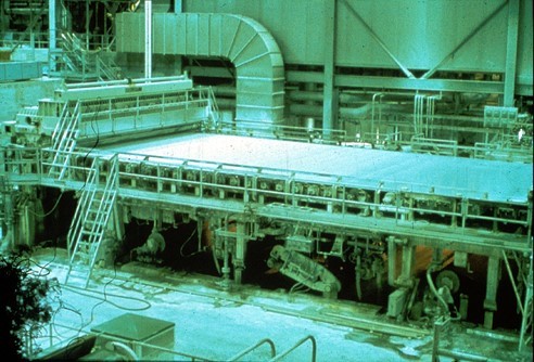
Fig. 1. Typical Fourdrinier forming section on a paper machine.
See Acknowledgements for figure credits and source information.
Jet Impingement
Drainage begins when the jet from the headbox impinges upon the wire. The kinetic energy of the jet creates a pressure, which produces substantial drainage due to the small resistance of the formed mat at this stage. Only the component of the jet velocity perpendicular to the wire creates pressure; therefore, it is important to control the angle and thickness of the jet discharging from the headbox.
The headbox orifice, called a “slice”, controls jet angle and thickness. The slice typically has a flexible top lip that “slices” into the jet at a sharp angle, as illustrated in Fig 2, in order to enable local changes in the orifice size by minimal local bending of the lip. The slice configuration controls two major characteristics of the jet: its angle relative to the bottom of the headbox, b, and its contraction coefficient, Cc. This coefficient reflects the reduced size of the jet due to a “vena contracta” imposed by the slice configuration. This coefficient multiplied by the slice opening, b, it gives the thickness of the jet, Ccb. This is the point where headbox pressure has fallen to zero, meaning that it is the thickness that corresponds to the jet velocity calculated from headbox pressure. The value of Cc can be as small as 0.62. Accordingly, using the slice opening as the jet thickness can result in significant error in calculating the volumetric flow from the headbox.
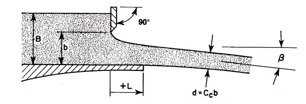
Fig. 2. Slice configuration showing the definitions of the key variables (from TAPPI TIP 0410-02)
As paper machine speeds increased over the years, control of the headbox jet became ever more critical. In a pioneering study, Nelson (1960) found that in the absence of gravity effects, two dimensionless numbers governed jet contraction and angle of outflow: the ratio of the bottom lip extension to the slice opening, L/b, and the ratio of the slice opening to the size of the channel upstream, b/B. These are illustrated in Fig 2. There was need to predict b and Cc in terms of these dimensionless parameters. Recognizing that the accelerating flow in a slice was largely inertial, Appel and Yu (1963) modelled the flow successfully as an inviscid fluid using potential flow theory. The result was expressed as parametric equations from which graphical plots could be made to give b and Cc in terms of L/b and b/B. These can be found in TAPPI TIP 0410-02, 03, 04.
With the growth of computer control, there was a further need to obtain b and Cc by direct calculation rather than by cumbersome interpolation from graphs. To meet this need, Kerekes and Koller (1981) developed explicit equations by generating large sets of data from the parametric equations and curve fitting empirical equations to these data using up to 10 empirical constants. This rather prosaic approach, building upon an elegant application of hydrodynamic potential flow theory, produced useable equations to directly calculate b and Cc values, which are given in TAPPI TIP 0410-02, 03, 04 and widely used.
The assumption of inviscid flow in the above analysis has yielded reasonable results for jet contraction and angle of outflow. However, it should be noted that boundary layers exist and play a key role in the development of Machine Direction (MD) streaks and jet stability (Soderberg and Alfredsson 2000).
Table Rolls
In early years at low machine speeds, it was thought that gravity caused drainage on a Fourdrinier forming table. Consequently, to increase machine speeds, tables had to be extended in length. However, it was found that as speeds increased, table rolls had to be removed rather than added. This means that the drainage capacity increased rather than decreased. There was some early suggestion that table rolls exerted a sucking effect, but this was a disputed concept. It was known that drainage was proportional to roll diameter. But how large could rolls be made to accommodate future speed increases?
Wrist (1954) was the first to suggest that table rolls induced a suction of magnitude ![]() in the diverging nip between the wire and table roll, as shown in Fig 3, ,where U is the wire speed and is the density of water.
in the diverging nip between the wire and table roll, as shown in Fig 3, ,where U is the wire speed and is the density of water.
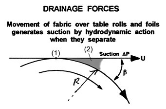
Fig. 3. Suction created in the outgoing nip of a table roll
The findings of Wrist (1954) were verified by Bennett (1954) up to 600 ft/min. He also found that roll diameter affected the area over which the suction acted, but not its magnitude.
Wrist and Bennet found, as well as others, that instabilities occur with table rolls. As a wire moves downstream from the top of a roll, suction bends the wire toward the roll, causing downward acceleration. Further downstream, the gap between the wire and roll surface increases, eventually to a point where the water in the nip splits apart, ending suction under the wire. This sudden release of suction causes an upward acceleration of the wire, which is restrained by tension, but the pulp suspension develops surface instabilities, as shown in Fig 4. Although some such “action” is desirable for formation uniformity improvement, too much of it causes a deterioration in sheet quality.
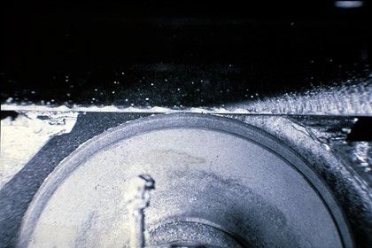
Fig. 4. Drainage on table roll and surface instability (movement is from left to right)
In the mid-1950s papermakers faced two serious obstacles to future speed increases. First, instabilities would increase to the point of destroying the formed web. Second, based on a simple estimate from ![]() , at about 900 m/min, suction would equal atmospheric pressure. Thus water would “boil” out of the sheet. As a result, further suction increases would not be possible, and the impact on the sheet could be disastrous. To some, this limitation was analogous to the “sonic” barrier in aviation flight. Clearly, there was a dire need for better understanding of the drainage process. This occurred 150 years after the invention of the Fourdrinier!
, at about 900 m/min, suction would equal atmospheric pressure. Thus water would “boil” out of the sheet. As a result, further suction increases would not be possible, and the impact on the sheet could be disastrous. To some, this limitation was analogous to the “sonic” barrier in aviation flight. Clearly, there was a dire need for better understanding of the drainage process. This occurred 150 years after the invention of the Fourdrinier!
In response to the need, intense scientific studies of Fourdrinier drainage were undertaken, many in Canada. Burkhard and Wrist (1956) carried out experimental studies on a pilot machine to measure both suction profiles and the amount of water drained by table rolls. Concurrently, G.I. Taylor (1956) performed a rigorous hydrodynamic analysis of table rolls. He obtained Eq. 1 for the maximum suction in the suction profile of the expanding nip and Eq. 2 for the amount of drainage, Q, induced by this suction. Wrist and Taylor both presented their classic papers at the Annual Meeting of the CPPA Technical Section Annual Meeting in Montreal in 1956.
![]() (1)
(1)
![]() (2)
(2)
Equation (1) confirmed Wrist’s equation, but only for the maximum suction in the suction pulse. Equation (2) showed that drainage increased as the cube of speed (U3). In his analysis, Taylor assumed that the flow velocity through the formed mat was proportional to the suction (laminar case). However, he noted that if flow resistance through the mat depended on the square of the draining velocity, as might occur at high drainage velocity, then Q would depend linearly on machine speed U rather thanU3. Around the same time, Bergstrom (1957) pointed out that neither of these predictions accorded with the findings of Burkard and Wrist and with practical experience. By back-calculating from Wrist’s experimental findings that Q was proportional toU2, he found that the flow through the mat depended onU1.33.
In subsequent work, Taylor (1958) analyzed table rolls using a different assumption from that used above: turbulent mixing in the drained water zone instead of flow streamlines of an ideal fluid. The solution for this case required a numerical approach. It gave a peak suction 1.4 times that of Eq. 1 as well as a larger zone over which the suction acted. Taylor noted, however, that Wrist’s measurements of peak suction accorded well with Eq. 1, not 1.4 times this amount. He concluded that this meant either that there was no turbulence or that the turbulence effect is balanced by friction loss in the water. This question remained unresolved.
Drainage Foils
In addition to table rolls, Burkard and Wrist (1956) measured suction and drainage for a stationary foil with a flare angle. They found that a suction pulse was also created in this case, but the peak value was less and the zone of the pulse was larger for rolls, as shown in Fig. 5.
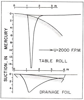
Fig. 5. Comparison of suction pressure created by a table roll and a foil (Wrist (1961)
In his 1958 paper, Taylor analyzed the hydrodynamics of a single foil, as shown in Fig 6, and presented his findings at the Annual Meeting of the CPPA Technical Section in 1958.
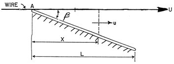
Fig. 6. A model foil
The resulting equations for maximum suction, pmax, and drainage, Q, for a foil, are given as:
![]() (3)
(3)
![]() (4)
(4)
In these equations, m is the dynamic viscosity of water; r is the density of water; k is the matt flow resistance; and L, is the foil length.
Equation 3 shows that suction depends linearly on flare angle, b, as illustrated in Fig 7.
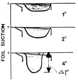
Fig. 7. Effect of flare angle, b, on suction pulse
As flare angle increases, the length of the foil over which suction can be exerted decreases, resulting in a maximum Q for a foil. The condition for this maximum may be obtained by equating the first derivative of (4) with respect to b to zero. The optimum occurs at:
![]() (5)
(5)
Fourdriniers typically operate at about ![]() .
.
These findings by Wrist and Taylor pointed the way to improved Fourdrinier forming by use of foils. However, another breakthrough was required to make foils a practical reality. At the time, “wires” were made of bronze. These were extremely sensitive to wear, to the extent that wire changes were required almost on a weekly basis. Bronze could not withstand the abrasion from rubbing over a stationary foil. After intense research by manufacturers, durable plastic “fabrics” of polyethylene and polyamide were developed to replace bronze wires. This opened the door to widespread use of foils in the early 1970’s. Further developments took place in developing foils with contoured shapes that enabled control over both drainage and surface instabilities to improve paper formation. As a consequence of all these efforts, today many Fourdrinier paper machines are in operation at speeds up to about 1200 m/min (Holik 2010).
TWIN-WIRE FORMERS
Early Years
The concept of forming paper by drainage between two converging wires is an old one. Indeed, as reported by Malashenko and Karlsson (2000) in their excellent review of the history of twin-wire forming, as far back as 1881 Tidcombe filed a patent for a former depicted in Fig. 8, which is astonishingly close to a major commercial twin-wire former introduced in 1968, 87 years after the patent!
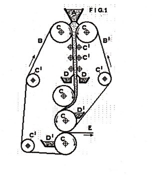
Fig. 8. From Tidcombe twin-wire former patent in 1881 (Malashenko and Karlsson 2000)
The benefits of “twin–wire” forming are obvious: faster drainage, less two-sidedness, and avoidance of surface instabilities. Early work started in the late 1940’s and accelerated in the 1950’s (Norman 1979). A major driving force was worry over the perceived speed limitation of Fourdrinier formers described above. Although the development of foils alleviated this concern, other shortcomings remained. By the late 1970’s, twin-wire forming became the dominant type of new formers for large paper machines. Broadly speaking, the early formers were of two types: roll formers and blade formers.
Roll Formers
In roll formers, the headbox jet is captured between two wires converging to wrap around a rotating roll, as shown in Fig 9. An essential feature of this former is the absence of relative motion between the wires and the roll. Roll formers produced good retention of small material (filler, fines), but rather poor formation, in particular formation having characteristic small grainy flocs.
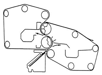
Fig. 9. Schematic of a “Papriformer” roll former
The principle of operation of roll formers was derived by Baines (1967) with the introduction of the Papriformer, which is shown in Fig 9. In essence, the headbox jet is captured in the wedge of an outer wire converging on wire on a rotating, as shown in Fig. 10.
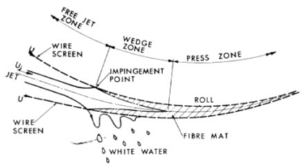
Fig. 10. Headbox jet entering wedge of roll former (Baines 1967)
As the nip converges, pressure on the draining suspension gradually increases to pressure p, determined by the wire tension T and the roll radius r according to the “membrane equation” (Eq. 6), which assumes that the wire has no appreciable stiffness.
![]() (6)
(6)
The link between this pressure and the headbox jet is through the Bernoulli equation. In essence, this is an energy balance between the velocity energy of the free jet and the pressure and velocity energies in in the gap. It gives,
![]() (7)
(7)
where Ur is the velocity of the wire and Uj the velocity of the jet, and variable p is the density of water.
This equation is only approximate, as it assumes no friction loss. However, it is apparent from Eq. 7 that for a real solution, ![]() , jet velocity must be larger than the roll velocity, i.e.
, jet velocity must be larger than the roll velocity, i.e. ![]() . This in turn means there must be machine direction shear within the zone of impingement where the jet is decelerated to roll speed. This further means that this former introduces a machine direction orientation of fibres.
. This in turn means there must be machine direction shear within the zone of impingement where the jet is decelerated to roll speed. This further means that this former introduces a machine direction orientation of fibres.
Good retention from this type of former has been attributed to low drainage velocity. The poor formation has been attributed to the absence of further hydrodynamic shear downstream of the impingement zone due to the absence of relative motion between the wire and roll surface.
Blade Formers
The other major type of twin-wire former is a “blade” former. Here the two wires pass over stationary blades located on both sides as the wires pass in a zig-zag fashion around them, or over blades on one side where the blades secured to a large-radius support structure. These are illustrated in Fig 11.
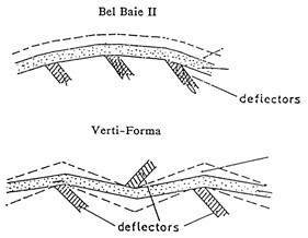
Fig. 11. Two types of blade gap formers
An early commercial blade former, the Vertiforma shown in Fig 12, was installed in 1968 in Quebec. Here the headbox jet flows downward into a gap of two converging wires, which then pass in a zig-zag fashion over stationary blades. This former gave very good formation but poor retention, and the system was hard to control.
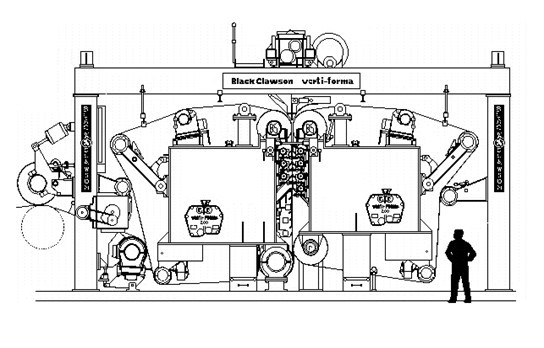
Fig. 12. The Vertiforma
Another blade former that became dominant in the market place at the time was the Bel-Baie II, as shown in Fig 13. Here the jet flowed upward to impinge between two wires which passed over stationary blades supported on one side by a large-radius structure. Thus, only one of the wires contacted blades. This former also gave good formation but poor retention. It also gave some two sidedness (differing properties at each surface).
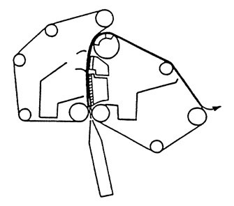
Fig. 13. Bel-Baie II former
Roll-Blade Formers
Surprisingly it took until the mid-1980s for the rather obvious next step in twin-wire forming: combine roll and blade formers to gain the advantage of each. Here initial drainage takes place in a roll former to preserve retention, followed by a blade forming section to create formation improvement. The first such commercial former, as introduced by Valmet, is shown in Fig 14.
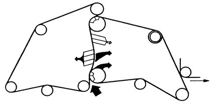
Fig. 14. A roll-blade former
A key factor in roll-blade formers is the consistency after initial roll dewatering. It must be high enough to preserve good retention, yet low enough to permit formation improvement in the subsequent blade section. This consistency has been found to be around 1.5 to 2.0%. In contrast, the typical consistency leaving the forming roll of a roll former is 6%.
Counter-Blades
There was a desire for more operator control of blade formers. This led to the introduction of “loadable counter blades”. Here, the blades on one side of the forming zone are secured to a moveable support that can be moved perpendicularly to the wires to increase the wrap around each blade. An example is shown in Fig 15.
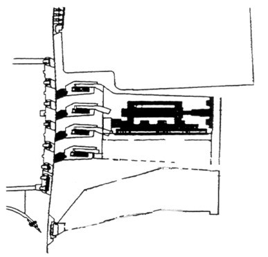
Fig. 15. Counter-blades in Bel Baie IV blade former (Beloit Corp)
Hybrid Formers
Yet another type of former is a hybrid former, a combination of Fourdrinier former followed by a twin-wire drainage section. An example is shown in Fig. 16.
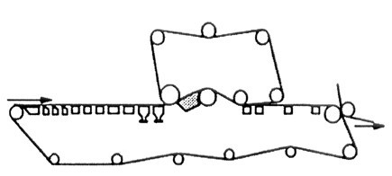
Fig. 16. A hybrid former
In a sense, this configuration was the earliest commercial twin-wire former, called the ”Inverfomer”, which had a very short table roll section before the top wire (Malashenko and Karlsson 2000). Later, hybrid formers became popular as retrofits to Fourdrinier formers in order to increase drainage capacity and gain some of the characteristics of twin wire formers, for example less two-sidedness.
Theoretical Understanding of Blade Formers
By the 1980’s blade formers became the dominant type of new twin-wire formers for large paper machines. Surprisingly, however, no one understood how they worked. For example, some early presentations for the Bel-Baie II (Fig. 13) claimed that good formation came about due to low pressure from the very large radius on which the blades were secured. Norman (1987) postulated that pressure pulses were created at the blade edges, but did not estimate their shape or speed dependence. The most significant contribution to knowledge at that time came from experimental measurements by the Beloit Corporation (Brauns 1986). He passed a pressure probe from the headbox up between the wires passing over blades on a pilot paper machine. As shown in Fig. 17, the findings showed an exponential rise to a peak pressure followed by a sharp decrease. Further, the size of the pressure had a strong dependence on speed.
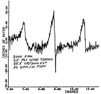
Fig. 17. Pressure pulses over blades measured in a pilot blade gap (Brauns 1986)
Given the growing popularity of blade forming, it is fair to say that the outstanding scientific problem in paper forming in the early 1990’s was a rigorous theoretical understanding of pressure and drainage caused by blades, analogous to the work of Taylor for Fourdriniers some 35 years earlier. In essence, the problem was one of a pulp suspension trapped between two wires moving at high speed while wrapping over a stationary element. The wrap causes a “pinching” action, which raises the pressure pulse between the wires. This pressure causes drainage through the wires and slows down the speed of the suspension relative to the wire speed. The size of the pressure pulse thus developed and the zone over which it extends depend on factors such as the angle of wrap, drainage resistance, wire speed, and gap thickness, all acting in combination.
In the early 1990’s, Zhao and Kerekes undertook to solve this problem and were the first to derive a rigorous theoretical model of pressure pulses created by blades and verify their findings by experiments on a pilot paper machine. The full paper was presented at the PAPTAC Annual Meeting in 1994 (Zhao and Kerekes 1994) and published later in journal form (Zhao and Kerekes 1996). In a separate work shortly afterwards, Zahrai and Bark (1995) developed a 2-D model, which in essence confirmed the Zhao–Kerekes predictions for 1-D to within a few percent. The Zhao-Kerekes theory considered an infinitely thin blade shown in Fig. 18. They derived an explicit expression, shown as Equation 8, for pressure p(x) in the machine direction upstream from the blade.
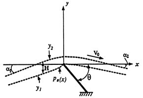
Fig. 18. Schematic of wires passing over thin blade (Zhao and Kerekes 1995)
![]() (8)
(8)
where
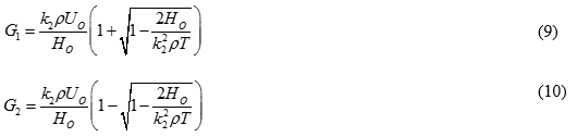
The variables in these equations not defined earlier are: k1 and k2, which are matt resistance on top and bottom wires; Ho, which the distance between wires at x=0;Uo, the wire speed; and T, wire tension.
Equation 7 shows the influence of key factors in blade forming and specifically revealed the following:
– dependence of pressure on speed (Fig. 19)
– pressure forms upstream of the edges of blades (Fig. 19)
– wide blades gave a pressure pulse at each edge; consequently, only the leading edge gives two-sided drainage
– pressure pulses on each edge of a wide blade converge into one pulse when blade width is reduced to about 10 mm (Fig. 20)
-under certain conditions, equations (9) and (10) have imaginary components ( ![]() ), meaning pressure oscillations can occur upstream of the blade
), meaning pressure oscillations can occur upstream of the blade
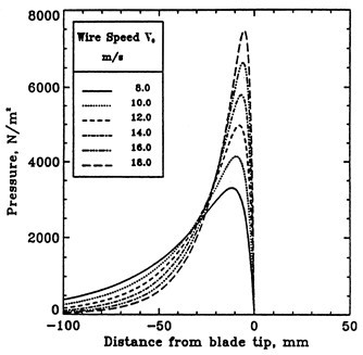
Fig. 19. Effect of speed on pressure between fabrics in blade gap former (Zhao and Kerekes 1995)
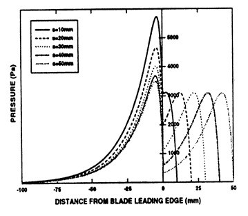
Fig. 20. Pressure pulses on each edge of wide blade converge to one pulse as blade width is reduced (Green et al. 1998)
Effect on Formation
In addition to water removal, the forming section plays a key role in formation (mass uniformity) of paper and retention of fine material. It is well known that a certain amount of surface instability on Fourdrinier tables improved formation. To facilitate this, practices were developed for positioning rolls and foils along the table to induce the “right” amount of agitation. In further advances, contoured foils were developed for this purpose. However, the scientific link between formation and forming hydrodynamics was limited to correlations between observed surface activity and measured formation improvement. The approach of Kiviranta and Paulapuro (1992) is an example. Causal links were never made nor attempted, as far as the authors know. It is clear that formation improvement must come about from movement of some fibres relative to others in the plane of the wire, and that this must be caused hydrodynamic action parallel to the wire, but it is not clear how surface instabilities cause such action.
Twin wire forming, being an enclosed flow, offered better possibilities for causal links. Strangely, however, this did not take place for the most common case, roll formers. These formers produce a characteristic “grainy” formation. No definitive hydrodynamic explanation has been proposed to account for this characteristic, despite much effort to do so (Malashenko and Karlsson 2000). On the other hand, progress was made with blade formers. These improve formation alone or when following roll forming (Nordstrom and Norman 1995). The cause reason lies in the nature of the pressure pulses described above.
The pulses impose pressure gradients in the MD direction, which cause local flow relative to the wire when the induced shear stress exceeds the yield stress of the pulp suspension. This occurs for a finite time, resulting in a displacement distance during the passage over a blade. This was calculated for a succession of blades by Zhao and Kerekes (1996). The cumulative displacement distance was correlated to formation improvement, as shown in Fig. 21.
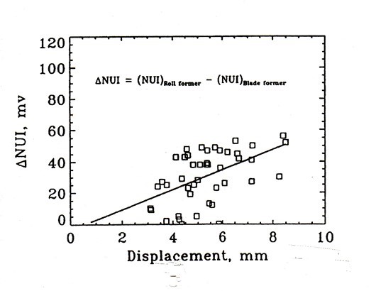
Fig. 21. Cumulative displacement distance over several blades correlates approximately with formation improvement (Zhao & Kerekes 1996)
The correlation is obviously very approximate, but it was the first causal link between forming hydrodynamics and formation improvement known to the authors. Subsequent work showed the limits of displacement possible at any one blade and the role of floc strength (Kerekes et al. 2007). In more recent work, Akesson and Norman (2006) directly measured pulp floc elongation and rupture during passage over a blade in a twin-wire former.
Retention and Fibre Orientation
The coupling of good formation and poor retention in blade formers may be explained in terms of the pressure pulses and velocities shown in Fig. 22. The large pressure gradients of the pulses cause the flow velocity, , which produces formation improvement, as discussed above. At the same time, these large pressure gradients lead to large pressures, which cause high drainage velocity, V, and consequently poor retention.
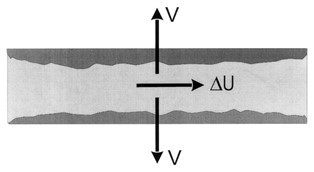
Fig. 22. Illustration of relative velocity in MD direction created by the pressure gradient and velocity V through the formed mat created by pressure
An additional effect of velocity is fibre orientation in the MD direction in the centre of the sheet. This not only affects the MD/CD strength of the sheet, but also lowers its z direction strength, as shown by Hasuike et al. (1995).
CLOSING COMMENTS
This paper has highlighted some of the key advances in the hydrodynamics of paper forming. In some cases, these advances have played a key role in technological breakthroughs, for example, in the introduction of foils to replace table rolls in Fourdrinier forming. In other cases, the advances assisted in optimizing the process, for example in the use of blades in twin-wire formers.
In closing, we should note that advances in other parts of papermaking contributed greatly to modern papermaking. Examples may be found in fluid mechanics research (Lundell et al. 2011) and equipment development such as multilayer headboxes, dilution CD control, and extended nip pressing. The collective impact of these contributions can be judged by the fact that modern paper machines process over a billion fibres per second to produce paper five fibre diameters thick at tolerances of only one or two fibres at speeds over 100 km/h.
ACKNOWLEDGEMENTS
The authors gratefully acknowledge permission from the following copyright holders to reproduce figures from the sources cited in the captions: TAPPI, Fundamental Research Society, PAPTAC, Pulp and Paper Canada, and Paperi ja Puu. In addition, the former MacMillan-Bloedel Research and Beloit Corp are acknowledged as the sources respectively of Figs. 4 and 15. Regrettably, the original sources of Figs. 1 and 7, which have been in circulation for many years, could not be identified. Nevertheless, the authors wish to thank all these contributors, even if unknown, for the use of their work in this retrospective article.
REFERENCES CITED
Akesson, K., and Norman, B. (2006). “Flow mechanism in twin-wire blade forming, Parts I and II,” Nordic Pulp Paper Res. J. 21(1), 59-66, 67-72.
Appel, D. W., and Yu, Y. S. (1963). “Free streamline analysis of flow from nozzles, flow through side inlets, and flow past corners: Studies in engineering mechanics,” No. 17, Center for Research in Engineering Science, University of Kansas, Lawrence, KS.
Baines, W. D. (1967). “The Papriformer Part II: Flow in the formation zone of a twin-wire machine,” Pulp Paper Mag. Can. 68(10), T497-T505.
Bennett, W. E. (1954). “Quantitative studies of water removal by table rolls,” TAPPI J. 37(11), 534-541.
Bergstrom, J. (1957). “Table roll drainage,” Svensk Papperstidning 60(1), 15.
Brauns, R. (1986). “Wet end developments,” Preprints, CPPA Tech Section Annual Meeting, A275-A282.
Burkhard, G., and Wrist, P. E. (1956). “Investigation of high-speed paper machine drainage phenomena,” Pulp Paper Mag. Can. 47(4), 100-118.
Green, S. I., Zhao, R. H., and Kerekes, R. J. (1998). “Pressure distribution between forming fabrics in blade gap formers: Blades of finite width and fabrics of finite stiffness,” J. Pulp Paper Sci. 24(2), 60-67.
Hasuike, M., Masuda, K., and Bando, T. (1995). “Characterization of three-dimensional sheet structure,” Mitsubishi Heavy Industries, Ltd., Technical Review, Vol. 32, No. 3 (Oct.).
Holik, H. (2010). “Faster, wider, better: Progress in paper machinery in the last 100 years,” O PAPEL 71(8), 66-93
Kerekes, R. J. and Koller, E. B. (1981). “Equations for calculating headbox jet contraction and angle of outflow,” TAPPI J. 64(1), 95-96.
Kerekes, R. J., Dalpke, B., and Jong, J. H. (2007). “The hydrodynamics of formation improvement by blades in twin-wire formers,” J. Pulp Paper Sci. 33(4), 183-187.
Kiviranta, A., and Paulapuro, H. (1992). “Characterization and optimization of Fourdrinier table activity in linerboard manufacture,” Pap. Puu. 74(9), 728-737.
Lundell, F., Soderberg, L. D., and Alfredsson, P. H. (2011). “Fluid mechanics of papermaking,” Annual Rev. Fluid Mech. 43, 195-217.
Malashenko, A., and Karlsson, M. (2000). “Twin-wire forming: An overview,” CPPA Technical Section Annual Meeting, Montreal, A189-A202, January 2000.
Nelson, H. C. (1960). “Paper machine inlet performance in relation to the Fourdrinier Wire,” TAPPI J. 43(4), 338-342.
Nordstrom, B., and Norman, B. (1995). “Effects of roll-blade and roll forming on formation, retention and mechanical properties and anisotropy,” J. Pulp Pap. Sci. 21(7), 223-229.
Norman, B. (1979). “Principles of twin-wire forming,” Svensk Papperstidning 82(11), 330-335.
Norman, B. (2000). “Web forming,” Papermaking Science and Technology, FAPET-TAPPI, Book 8
Norman, B. (1987). “On the mechanisms of dewatering in twin-wire and press section,” Nordic Pulp Paper Res. J. 3(Special Issue), 39-42.
Soderberg, L. D., and Alfredsson, P. H. (2000). “Experiments concerning the origin of streaky structures inside a plane water jet,” J. Pulp Paper. Sci. 26, 395-400.
Taylor, G. I. (1956). “Drainage at a table roll,” Pulp Paper Mag. Can. 57(3), 267-273.
Taylor, G. I. (1958). “Drainage at a table roll and foil,” Pulp Paper Mag Can. 59C, 172-176.
Tidcombe, G. (1881). “Apparatus for making paper and board from vegetable, animal or mineral substances,” British Patent No 4182, Sept 28, 1881.
Wrist, P. E. (1954). “The papermaking process as a filtration problem,” Pulp Paper Mag. Can. 55(6), 115-119.
Wrist, P. E. (1961). “Dynamics of sheet formation on the Fourdrinier machine,” 2nd Fundamental Research Research Symposium, Technical Section of the British Paper and Board Makers Association, London, Vol.2, p. 839.
Zahrai, S., and Bark, F. H. (1995). “On the fluid mechanics of twin wire blade forming in paper machines,” Nordic Pulp Paper Res. J. 4, 245-252.
Zhao, R. H., and Kerekes, R. J. (1994). “Pressure distribution between forming fabrics in blade gap formers: Thin blades,” 80th Annual Meeting, Tech. Section, CPPA, Feb 1-4(1994), & J. Pulp Paper Sci. 1995: 21(3), J97-J103.
Zhao, R. H., and Kerekes, R. J. (1996). “The effect of consistency on pressure pulse in a blade gap former,” Paperi Ja Puu 78(1-2), 36-38.
Article submitted: December 11, 2016; Peer review completed: January 21, 2016; Revised version received: January 24, 2017; Revised version accepted: January 28, 2017; Published: February 1, 2017.
DOI: 10.15376/biores.12.1.2125-2142