
Abstract
The goal of this study was to collect up-to-date data on the properties of Canadian and United States-manufactured particleboard (PB) and medium density fiberboard (MDF). Sixty-three manufacturers were contacted and asked to participate in a mechanical and physical properties comparison study. This is the first of two papers presenting the results of the PB evaluation. Samples from five different manufacturing facilities from Canada and the United States were evaluated. Each manufacturing facility provided 5 full-sized, (2440 x 1220 mm) M2-grade panels. These were tested according to North American standards. The performed tests included internal bond (IB), bending and elastic moduli (MOR/MOE), thickness swelling (TS), linear expansion (LE), vertical density profile (VDP), and face and edge screw withdrawal resistance (SWR). Four out of 5 press lines exceeded the American National Standards Institute (ANSI) A208.1 (2009) recommendation for IB. Only one of the tested particleboard sets reached the recommended ANSI standard for MOR. Results for the edge SWR showed that none of the tested particleboard manufacturers reached the ANSI recommended value.
Download PDF
Full Article
Comparing Properties of North American Manufactured Particleboard and Medium Density Fiberboard – Part I: Particleboard
Jörn Dettmer and Gregory D. Smith*
The goal of this study was to collect up-to-date data on the properties of Canadian and United States-manufactured particleboard (PB) and medium density fiberboard (MDF). Sixty-three manufacturers were contacted and asked to participate in a mechanical and physical properties comparison study. This is the first of two papers presenting the results of the PB evaluation. Samples from five different manufacturing facilities from Canada and the United States were evaluated. Each manufacturing facility provided 5 full-sized, (2440 x 1220 mm) M2-grade panels. These were tested according to North American standards. The performed tests included internal bond (IB), bending and elastic moduli (MOR/MOE), thickness swelling (TS), linear expansion (LE), vertical density profile (VDP), and face and edge screw withdrawal resistance (SWR). Four out of 5 press lines exceeded the American National Standards Institute (ANSI) A208.1 (2009) recommendation for IB. Only one of the tested particleboard sets reached the recommended ANSI standard for MOR. Results for the edge SWR showed that none of the tested particleboard manufacturers reached the ANSI recommended value.
Keywords: Particleboard; M2-grade; Internal bond; Mechanical properties; Thickness swell; Linear expansion; Vertical density profile; Screw withdrawal; Survey
Contact information: Department of Wood Science, The University of British Columbia, 2935-2424 Main Mall, Vancouver, BC, V6T 1Z4, Canada; *Corresponding author: greg.smith@ubc.ca
INTRODUCTION
Non-structural panels, such as medium density fiberboard (MDF) and particleboard (PB), are commonly used interior building materials that offer good dimensional stability and a smooth surface that can be painted, laminated, or veneered. They are widely used in shelving and other cabinetry and furniture applications, as well as for sub-flooring (mainly PB). In North America, PB and MDF are the most widely used non-structural engineered wood products for furniture and furniture parts (Tabarsi et al. 2003).
Surveys on the properties of PB and MDF produced in the U.S. and Canada have been performed in the past. Semple et al. (2005a,b) surveyed 6 Canadian plants that produced 5/8” M2-grade, as well as a comparison study of MS- and M2-grade PB from two Canadian manufacturers. In 1994, Bautista (1994) and Zhang (1994) compared the mechanical properties of PB from 25 mills. Also in 1994, Cassens et al. (1994) measured and compared the properties of 3/8” thick M2-grade PB from 7 different production lines, representing 4 different manufacturers.
The motivation for this study was the constantly changing nature of the wood composites market. Fluctuations in raw material supply, costs, new formaldehyde emissions regulations, and advancements in the production technology of PB and MDF, e.g., resin and resin delivery systems, suggest that the products produced today may have different properties than those produced a decade ago. The key objective of this study was to identify and compare the mechanical and physical properties of U.S. and Canadian manufactured PB and MDF. The goal of the survey was to identify panel characteristics, furnish compositions (including species and particle/fiber sizes), resin delivery systems, and the mechanical properties of the boards. In this first of two papers, sample boards from five Canadian and US PB production facilities were evaluated; sample boards for MDF properties were evaluated in part 2 (Dettmer and Smith 2015).
EXPERIMENTAL
Materials
Sixty-three PB and MDF manufacturers were contacted and asked to participate in the properties comparison study. Each participating PB manufacturer provided five, M2-grade (ANSI 208.1 2009) 2440 x 1220 mm panels.
It proved difficult to engage and encourage manufacturers to provide panel sets for the properties comparison study. Three PB sets were donated by interested plants, one set was purchased from a local building supplies store (Home Depot), and one set was obtained with the help of a resin company colleague encouraging those plants to participate in the study. The various sets of panels were received between July and September, 2012. A total number of 25 PB panels were tested. Preparation of the samples began in August 2012.
Properties of interest
The properties of interest are listed in Table 1. These included internal bond (IB), vertical density profile (VDP), thickness swell (TS), linear expansion (LE) in both directions, parallel (‖) and perpendicular (⊥) to machine direction, face screw withdrawal resistance (fSWR), edge screw withdrawal resistance in both directions (eSWR ‖, eSWR ⊥), modulus of rupture in both directions (MOR ‖, MOR⊥), and modulus of elasticity in both directions (MOE ‖, MOE ⊥).
Table 1. Specimen and Number of Samples Evaluated for Properties of Interest

Specimen IDs correspond with the label numbers in Fig. 1b
Cutting patterns for the samples
Each panel was cut into eight 61 x 61 cm sub-panels using a Martin sliding table saw (Martin T75 PreX, Germany) and labeled according to the cutting pattern shown in Fig. 1a. In order to avoid any location bias, the subpanels were randomly assigned to one of eight different cutting patterns, two of which are shown in Fig. 1b. Each cutting pattern contained all the necessary specimens according to ASTM D1037–06a to benchmark the properties in question.

Fig. 1. The a) labeling sequence for the sub-panels and b) two of eight cutting patterns. The label numbers correspond with the specimen IDs in Table 1.
Before cutting, each specimen was labeled with a unique ID that contained information about the mill, panel replicate (1 to 5), sub-panel (1 to 8), and machine direction of the mat (parallel or perpendicular). The machine direction was the panel orientation that corresponded with the direction that the mat moves through the production line. For multi-opening presses, the machine direction usually corresponded to the long edge of the panel, whereas for continuous presses, the machine direction corresponded to the short edge of the panel. When the machine direction was unknown, it was assumed that the machine direction corresponded to the long edge of the panel. A 3-digit stamp was used to label the specimens. The machine direction was indicated by the orientation of the stamp (parallel or perpendicular to the long edge of the specimen). To ensure the label was clearly visible and not being compromised by the sawdust from the cutting process, the label was applied using a jig prior to cutting. In order to keep the collected information confidential, manufacturers were indicated by a randomly assigned letter. One manufacturer (Manufacturer B) was discarded due to different panel thicknesses. Therefore, samples from this manufacturer did not appear in the study. The specimens were cut, using a Routech Record 121 CNC (Computer Numerical Control) Router (Italy). The 4 x 10-ft flat table machine allows for loading on one side and machining on the other end of the table, simultaneously. This resulted in a high throughput, and one person was able to cut all 4800 samples in approximately 40 h. A similar study at the University of British Columbia by Semple et al. (2005b,c), with half the number of samples, took 2 people more than 6 weeks. The machine had a vacuum aluminum table with a square grid pattern that, in combination with a closed-cell gasket and spoil boards, allows nested-based machining. The eight random cutting patterns were designed using the CAD (Computer Aided Design) software (SolidWorks Corp., Waltham, MA, USA). In order to reduce the number of spoil boards, the eight cutting patterns were based on 4 different patterns that were then rotated 90° or 180°, resulting in eight different cutting patterns. A complete description of the cutting patterns can be found in Dettmer (2013). This not only reduced the number of required spoil boards, but also the programming time for the computer aided manufacturing (CAM) software (MasterCam, Tolland, Connecticut, United States) .
Factors and levels
The experimental design to analyze the collected data consisted of a completely randomized design (CRD) with one factor and fixed effects with subsampling. The manufacturers (A through F) were the treatments (fixed effects), and the boards for each manufacturer were the experimental units (replicates, n=5), nested within the manufacturers. The specimens that were cut from each sub-panel represented the subsampling units (observations, m=8). This experiment was a balanced case of subsampling; an equal number of experimental units (n) were applied per treatment and a constant number of observations (m) were made per experimental unit (Kutner et al. 2004).
To analyze the data at a 5 percent significance level, the statistical analysis software package SAS (USA) was used with the PROC MIXED procedure under the assumptions of independence of the observations, normal distributed data sets, and equality of variances. In those cases where the assumption of equal variances was not met, the more robust Games-Howell test, which can cope with unequal variances, was used. This test identifies means that are significantly different but does not compute a Least Significant Difference (LSD).
Methods
Conditioning
Prior to testing, all specimens were conditioned for a minimum of two weeks. Specimens were stacked between stickers in a conditioning room at 20 ±1 °C and 65 ±5% relative humidity (RH). Near the end of the two-week conditioning phase, samples were weighed daily to ensure that they had reached constant mass.
Specific gravity, density, and moisture content
The specific gravity (SG) of the samples was determined in accordance with ASTM 2395-07a, method A, volume by measurement. For this purpose, the thickness swell samples were used, since the samples met the requirements of a minimum surface area of 58 cm². The basis for SG was the oven-dry weight and the conditioned specimen volume (65 ±5% RH, 20 ±3 °C).
The vertical density profile (VDP) was measured using an X-ray density profiler (Model QDP-01X, Quintex Measurement Systems, USA). The IB samples were used prior to IB testing to measure the density through the thickness of the panel at intervals of 0.06 mm. The profiler was set up for a VDP graph output. Measurements included average calculated density (based on sample measurements taken prior to testing), average measured density (based on measured VDP), maximum and minimum measured density, and densities for pre-defined zones, such as peak face densities (PFD) for both surfaces, mid-panel density (at 8.1 mm), and average core density (CD) for a defined zone and its standard deviation. The moisture content was measured in accordance with ASTM D 4442-07, method B. After completing the thickness swell tests, the samples were dried at 103 ± 2 °C, until reaching oven-dry constant mass, and were weighed.
Thickness swelling
Thickness swelling tests were performed in accordance to ASTM D1037-06a method A, a 2 h plus 22 h submersion.
After conditioning, the 152 x 152 mm sample weights and dimensions were measured and recorded. To determine the thickness, each sample was measured at four points, 25 mm in from the edge and midway along each side. These four values were used to calculate the average thickness for each sample. The specimens were then horizontally submerged under 1 inch of water, using a custom-made swell tank. The water temperature was held at 20 ±1 °C. After 2 h, the samples were removed from the tank, drained, and weights and thicknesses were measured. The samples were then submerged for an additional 22 h and measured in the same fashion.
Internal bond
The internal bond is the tensile strength perpendicular to the surface. In the wood composite panel industry, it is a commonly used measure of the resin performance. For the test, two specimen blocks were glued to the top and bottom surfaces of the specimens using a hot-melt adhesive. The specimens were then attached to the loading fixture of the test machine, and tension was applied perpendicular to the specimen surface until specimen failure.
Two hundred samples (50 x 50 mm) were tested using an Instron Series 3300 load frame (USA). For each sample, IB was calculated using the maximum load, measured by the load frame, and the dimensions prior to the VDP testing.
Modulus of rupture and modulus of elasticity
Samples for the static bending test, ASTM D1037, measured 76 x 432 mm. The testing was done on a Sintech 30/D load frame using the TestWorks testing control system (MTS Systems, USA). The span for the center point loading test was 381 mm and the supports and loading points were rounded. Prior to testing, the width and thickness of the samples were measured in order to calculate the MOR and MOE. The samples were loaded at the center of span, and the load was applied to the samples at the midpoint at a rate of 7.7 mm/min. Equal numbers of samples from each sub-panel were tested face-up and face-down.
Screw withdrawal resistance
For all SWR tests, a 1-inch Number 10 sheet-metal screw (Pan Head Cross Recessed Drive, Type AB, 18-8 stainless steel; Fastenal, USA) was used. The root diameter of the screw was 3.51 mm with a pitch of 16 threads per inch.
The samples for the fSWR, measuring 76 x 102 mm, were pre-drilled prior to inserting the screw. The resulting pilot hole had a diameter of 3.2 mm (0.9 off the root diameter of the screw). This screw was threaded 17 mm into the sample at a right angle to the face of the panel.
The samples for both eSWR tests (parallel and perpendicular), measuring 76 x 152 mm, were pre-drilled at mid-thickness at a right angle to the surface of the edge using the same drill bit. This screw was threaded 17 mm into the pilot hole.
The specimens were installed in the testing assembly, screw head facing up, and loaded at a rate of 1.5 mm/min and the maximum load required to withdraw the screw from the panel was recorded.
Linear expansion
Testing the linear expansion revealed information about the dimensional stability of the panels with changes in moisture content. Every sub-panel had one specimen with the long side parallel and one specimen with the long side perpendicular to the long edge of the panel, each measuring 76 x 305 mm.
For the test, specimens were stacked in racks and conditioned to equilibrium at an RH of 50% and 20 °C. After reaching equilibrium, the length of the samples was measured and recorded, utilizing a custom-made gauge. The samples were then conditioned to equilibrium and the length was measured again. It should be mentioned that the samples were measured the same way after each conditioning period, with the label facing up towards the operator for the perpendicular samples and label facing up towards the right of the operator for the parallel samples.
RESULTS AND DISCUSSION
The results from the statistical analysis are presented in Table 2. When applicable, the physical and mechanical properties were compared to the appropriate voluntary ANSI standard, namely ANSI A208.1 for PB. Further, the older ANSI A208.1 (1999) and the most recent ANSI A208.1 (2009) are both presented with the purpose of comparing the findings in this study with older studies that used the standard from 1999. The major change between the two standards was that the new ANSI specified values (ANSI A208.1 2009) for IB, MOR, MOE, and SWR represent a lower specification limit. In order to meet or exceed the 2009 standard, the 5th percentile values were equal to or greater than the values specified in the ANSI standard from 1999. In comparison, the values for the above mentioned properties in the 1999 standard were based on a 5-panel mean, where no single panel mean shall be 20% lower than the specified value.
Moisture Content, Specific Gravity, Vertical Density Profile, and Internal Bond
The specific gravity (SG) and moisture content (MC) are shown in Fig. 2a and b for each manufacturer. The mean specific gravities of the 5 PB sets ranged from 710 kg/m3 for Manufacturer D (CV= 1.8%) to 596 kg/m3 for Manufacturer E (CV= 2.1%). There were no significant differences (α= 0.05) between Manufacturers A and C, with means of 640 kg/m3 (CV= 2.5%) and 627 kg/m3 (CV= 4.4 %) nor between Manufacturers E and F (604 kg/m3, CV= 2.8%).
Table 2. Means and Coefficients of Variation (CV) of Physical and Mechanical Properties of PBs from Manufacturers


Fig. 2. The a) specific gravity and b) moisture content of M2-grade particleboard according to manufacturer. Each mean value represents 40 samples tested. Means with the same lower case letter above the column are not significantly different at = 0.05.
The manufacturer with the highest moisture content was Manufacturer A, as shown in Fig. 2b, with an average MC of 12% (CV= 2.4%). The lowest MC of 10.9% (CV= 3.1%) was measured for Manufacturer D. No significant differences were observed between Manufacturers A and F, C and F, or D and E.
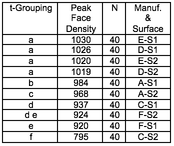
The comparison of VDP means is shown in Fig. 3a. Peak face densities (PFD) ranged from 1030 kg/m3 (CV= 2.7%) for surface one (S1) of Manufacturer E to 795 kg/m3 (CV= 4.5%) for surface two (S2) of Manufacturer C. The highest CD, averaged over a 6 mm zone around the middle of the board, was observed for Manufacturer D (670 kg/m3, CV= 2.2%). Manufacturer E had the lowest CD of 539 kg/m3 (CV= 3.3%).
For both, PFD and CD analyses, the assumption for equal variances was not met (H0 was rejected), and multiple means comparison using Fisher’s LSD and the robust Games-Howell test yielded the same results. Manufacturers A and F, and C and F did not show significant differences between means for core density. Figure 3b shows the significant differences for the PFDs. With the exception of Manufacturer C, who had the lowest mean IB value of 0.32 MPa (CV= 23.9%), there were no significant differences in the mean IB values for the other manufacturers.
Manufacturer D had the highest IB strength of 0.53 MPa (CV= 14.4%). All manufacturers, except Manufacturer C, met the voluntary ANSI A208.1 (1999) and ANSI A208.1 (2009) standards for M2-grade PB. A visual comparison of the two standards is shown in Figs. 3c and d; although the values for the lowest 5th percentile values were slightly lower than the means, the trend was similar for both presentations.
The well-known correlation between panel density/specific gravity and IB (Lehmann 1970) was observed within the results. Manufacturer D, with the highest SG and core density, also had the highest IB. However there were some discrepancies; Manufacturer C, with a significantly lower mean IB value than all other manufacturers, did not have the lowest SG or the lowest core density. Manufacturer E also had very low CD, but a high IB. Other factors that affect IB included resin type and content, moisture content, and furnish properties like wood species and particle size; however, many of these properties were unknown in this survey

(b)


Fig. 3. The a) VDP expressed as the mean of peak density surface one (S1), core density averaged over a 6-mm zone (C), peak density for surface two (S2) for the five PB sets, and b) the significance grouping for the peak density. The means are sorted from highest to lowest. Note: The lowercase letters in the t-Grouping do not correspond with the letters for the manufacturers. The c) means for IB strength for the five PB manufacturers (n= 40). The horizontal line indicates the minimum IB value required to meet the voluntary ANSI A208.1 (1999) standard. The d) lower 5th percentiles of the normally distributed IB strength are presented in accordance with the new ANSI A208.1 standard from 2009. Means with the same lower case letter above the column are not significantly different at = 0.05.
According to the survey, Manufacturer C (with the lowest IB) exclusively used UF resin, with unspecified resin content. Manufacturer D, with the highest IB, did not specify resin content, but listed MUF/UF (face/core) and occasionally NAUF/MUF (face/core) as the combinations used for PB production. In work by Oh (1999), two sets of PB samples were made: one with UF resin and the other with MUF resin. In all other respects, the two sets of boards were identical. Oh did not find any significant difference in IB strength between UF and MUF bonded PB, and therefore it is unlikely that the difference in our study can be attributed to these particular resin types, but it may be related to resin content, as this was not disclosed by the manufacturers in the survey.
Manufacturer C used spruce and pine sources with core particle sizes of 8 to 35 mesh for the furnish, and Manufacturer D used southern yellow pine with core particle sizes of 7 to 100 mesh and fines (pan). Different wood species used in the furnish have been reported to affect the IB of wood composites (Kelly 1977). Furthermore, the composition of the furnish in regards to particle size distribution may have had a significant impact on the IB. For example, Sackey et al. (2008) used a customized furnish mix that increased the IB by up to 40%.
Despite a relatively low variation in SG and CD within manufacturers (CVs of 2 to 6%), the IB results demonstrated larger variation within manufacturers, with CVs of 9% (Manufacturer A) to the disproportionately high CV of 24% for Manufacturer C. The CV for IB of the five boards of Manufacturer C ranged from 18.3% (Panel 5) to 35.7% (Panel 4), and the remaining three panels were around 22%. The reason for this high variability is unknown; however, resin distribution and variations in the furnish are likely candidates. Semple et al. (2005b) found similar results, especially in regards to the IB variation within manufacturers.
It should also be pointed out that most manufacturers, except for Manufacturer C, had the expected U-shaped VDP; VDPs typical of the other manufacturers and that of Manufacturer C are compared in Fig. 5. The mean PFDs for both surfaces (S1 and S2) of panels from Manufacturer C had a significant difference of 142 kg/m3.
Even though Manufacturer A showed significant differences in PFDs (∆PFD = 15.7 kg/m3, ∆LSD = 14 kg/m3), the VDP plots were far more consistent than those of Manufacturer C (Fig. 4). Possible causes for an inconsistent VDP include differences between the furnish parameters, resin distribution, or resin pre-cure (Wong et al. 1999); however, it is more likely the result of unequal sanding of the faces.


Fig. 4. Comparison of typical VDP plots from a) Manufacturer A and b) Manufacturer C. The significant difference between PFDs is very pronounced for Manufacturer C.
Thickness Swell and Water Absorption
The TS after 2 h and 24 h are reported as the percentage of the conditioned sample thickness (Fig. 6a). It ranged from 4.8% (CV = 8%) for Manufacturer D to 25.5% for Manufacturer C (CV = 14.2%). The Games-Howell multiple pairwise comparison test showed significant differences between all means. The CVs were between 8% (Manufacturer D) and 18.4% (Manufacturer F).


Fig. 5. The a) thickness swelling after 2 h and 24 h for PB manufacturers and b) water absorption after 2 h and 24 h. All means (n = 40) are significantly different.
The means of water absorption (WA), presented in Fig. 5b, were based on the initial sample weight after conditioning. Manufacturer D had the lowest WA of 12% (CV= 7.7%), and Manufacturer A had the highest WA of 47.7% (CV= 11.3%). Means of Manufacturers A and C were not significantly different according to the Games-Howell test.
Generally, higher TS values are correlated with higher WA, which in turn is often associated with a higher board density (Halligan and Schniewind 1974). A notable discrepancy here (Table 3) was the very low TS, but relatively high SG and WA for Manufacturer A. Lower MC, as an explanation for the higher water absorption of Manufacturer A, can be ruled out, since it had the highest shipped MC. In their review of thickness swelling, Halligan and Schniewind (1974) summarized that TS is influenced by parameters such as wood species, particle geometry, blending efficiency, resin level, board density, densification, and pressing conditions. Medved et al. (2011) concluded that the condition of the core furnish, of three layer PB in regards to resin content, has a higher impact on TS than changing resin content in the surface layer. Table 3 compares the known properties of the manufacturers A and C.
Table 3. Comparison of Manufacturers A and C

The different wood species used by the two manufacturers was a possible explanation for the observed discrepancies between TS and WA. Particle size, compressibility, sorption properties, and anatomical and chemical composition of the wood species have an impact on TS and WA. The significantly better performance in TS and WA of Manufacturer D was most likely related to resin type and resin content of the core furnish. Oh (1999) found significantly lower percentages for TS and WA for boards manufactured with MUF resin than boards made with UF resin. The combination of the low percentage in TS and WA and the significantly higher CD (Fig. 3a) suggested a higher resin content. A high CD, achieved through higher densification of the furnish, can be ruled out since this would have resulted in a higher TS.
Linear Expansion
Mean LE values were between 0.32% (CV= 15.7%) for Manufacturer E, perpendicular to machine direction, and 0.87% (CV= 10.8%) for Manufacturer C, perpendicular to machine direction. Machine direction had no significant effect on panels from Manufacturers D and E (Fig. 6).

Fig. 6. Mean linear expansion (LE) values. Each pair of columns represents each manufacturer with two sample orientations tested (n‖ = 40, n⊥ = 40). Means with the same lower case letter above the column are not significantly different at α = 0.05 (a = highest mean, g = lowest mean).
The CVs ranged from 6.9% for the samples of Manufacturer A (perpendicular to machine direction) to 15.7% for the above-mentioned samples of Manufacturer E.
The results were not compared to the ANSI standard. In contrast to ASTM D1037, the ANSI standard maximum values are for a RH range from 50% to 80%, whereas the values presented here represent a RH change from 50% to 90%. Cassens et al. (1994) used a RH range from 39% to 68% to collect the LE data and pointed out that this smaller range was more representative of the end-use of M2-grade PB. They found the LE results to be highly variable, with a combined CV of 35%. Semple et al. (2015) found a significant board thickness effect on LE (65% to 95% RH) in PB; 0.42% and 0.25% for 6-mm and less dense 9-mm thick PB, respectively. The LE for all seven evaluated commercial PB manufacturers ranged from 0.14% to 0.34%, with a change in RH from 39% to 68%. Linear expansion was between 0.7% and 1.8% with an overall CV of 28% for an RH range of 39% to 98%.
In the past, several studies showed that particle geometry and particle orientation distribution (machine direction effects) are important factors affecting the LE of PB (Kelly 1977; Xu and Suchsland 1997; Rofii et al. 2013). A more oriented particle distribution resulted in a larger difference of LE between the two tested directions of the same PB (‖ and ⊥ to machine direction). This suggests that Manufacturers A, C, and F, with a significant effect of machine direction on that property mean, have a more oriented particle distribution than Manufacturers D and E. Miyamoto et al. (2002a) found that PB made with Hinoki particles (Japanese cypress) showed an increase in LE with decreasing particle size. Further, Suzuki and Miyamoto (1998) concluded in their study evaluating the effect of resin content (RC) on LE, that an increase of RC (PF resin) from 6% to 12% increased the LE. They did not find any clear reasoning for this phenomenon but listed differences of the layer structure and hygroscopicity of PF resins cured in the boards as possibilities for further investigation. Although the resin type for Manufacturer D was unknown (MUF/UF or NAUF/MUF), Suzuki and Miyamoto’s (1998) findings offered an explanation for the higher LE and the previously stated hypothesis of higher resin content for this manufacturer.
Screw Withdrawal Resistance
Face screw withdrawal resistance
The fSWR showed a trend similar to the previously presented results for IB, SG, VDP, and TS. The fSWR was highest for Manufacturer D (1182 N, CV = 7.3%) and lowest for Manufacturer C (776 N, CV = 14.4%). Fisher’s LSD test, as illustrated in Fig. 7a, revealed no significant difference in means for Manufacturers A and E. The CV range was between 7.3% (Manufacturer D) and 14.4% (Manufacturer A).


Fig. 7. The a) mean fSWR values. Each column represents one manufacturer (n = 40). Means with the same lower case letter above the columns are not significantly different at α = 0.05 (a = group with highest mean, d = group with lowest mean). The b) lower 5th percentile of the fSWR is presented in accordance with the new ANSI A208.1 standard from 2009.
Manufacturers A, D, and E met or exceeded both the ANSI A208.1 (1999; Fig. 7a) and ANSI A208.1 (2009; Fig. 7b) standards. Manufacturers C and F did not meet either standard.
Departures from the ASTM recommended minimum thickness are tolerated if “other considerations make it desirable to test with the thickness as manufactured” (ASTM 2010). The preparation of the samples for this study was similar to the study of Semple et al. (2005b), which found comparable fSWR means of 880 N to 1170N (CV = 7% to 11%).
Edge screw withdrawal resistance
Machine direction had no significant effect on the eSWR, and therefore the values were pooled across machine direction and re-analyzed with the appropriate ANOVA. The Games-Howell multiple comparison procedure did not show any significant differences between Manufacturers A, D, and E, and Manufacturers C and F. The mean eSWRs of the first group were in a close range from a low of 747 N (Manufacturer E, CV= 6.3%) to a high of 777 N (Manufacturer D, CV= 10.4%). The values of the second group with overall lower eSWRs, ranged from 597 N (CV= 17.8%) for Manufacturer C to 639 N (CV= 9.3%) for Manufacturer F. All manufacturers failed to meet the voluntary ANSI A208.1 (1999) and A208.1 (2009) standards for M2-grade PB, as shown in Fig. 8.


Fig. 8. The eSWR for the evaluated PB manufacturers. The a) mean values (n=40) compared to the ANSI standard from 1999. Means with the same lower case letter above the columns are not significantly different at α = 0.05. The b) lower 5th percentile of the eSWR compared to the ANSI standard from 2009
Values for eSWR were approximately 25% to 35% lower than fSWR. This was somewhat in accordance with Semple et al. (2005b), who reported a difference of 25%, but smaller than Cassens et al. (1994), who found eSWR to be 65% lower than fSWR. This difference was most likely related to the two different screw sizes that were used for the test (1” No. 10 woodscrew for fSWR and 1” No. 6 woodscrew for eSWR). Both also reported a higher CV range for eSWR than for fSWR. Semple et al.(2005b) explain the higher variability of eSWR with the lower CD and greater structural heterogeneity due to the presence of coarser particles in the core layer. For this study, the CV range for eSWR was slightly higher (6.3% to 17.8%).
Similar to fSWR, Semple and Smith (2005) found little or no correlation between CD and eSWR for the 20 evaluated, commercially-produced, PB panels from two press lines. For this study, correlations were low for eSWR and SG (R2 = 0.24), CD (R2 = 0.21), and IB (R2 = 0.5).
Modulus of Rupture and Modulus of Elasticity
For MOR, machine direction had a significant effect only for Manufacturer A. Figure 9a shows the mean MORs, sorted by machine direction and manufacturer. Manufacturer E had the highest MOR of 14 MPa (averaged across machine direction). The lowest MOR of 9.5 MPa was found for Manufacturer C, who also had the highest CV of 22%. The CVs for the other manufacturers were between 8% and 12% (Table 2). None of the tested PB manufacturers reached the recommended ANSI A208.1 (1999) value of 14.5 MPa. However, as shown in Fig. 9b, Manufacturer E complied with the newer ANSI A208.1 2009 standard that supersedes the older standard from 1999.


Fig. 9. The MOR for the evaluated PB manufacturers for both machine directions. The a) mean values (n=40) for MOR of each manufacturer. The horizontal line represents the ANSI standard from 1999. Means with the same lower case letter above the columns are not significantly different at = 0.05. The b) lower 5th percentile of the MOR lower strength is compared to the ANSI A208.1 standard from 2009.
The results for MOE were similar in regards to the ranking of the manufacturers. Manufacturer E had a significantly higher MOE for samples tested perpendicular to the machine direction (MOE ⊥= 3.1 MPa). The lowest MOE was found for Manufacturer C, perpendicular to machine direction (MOE ⊥= 2.0 MPa). The effect of machine direction on MOE was more pronounced than for MOR. Only Manufacturers D and F did not show a significant difference between machine directions (Fig. 10).


Fig. 10. The a) mean MOE values for both machine directions for each manufacturer. The horizontal line represents the ANSI A208.1 standard from 1999. Means with the same lower case letter above the columns are not significantly different at α = 0.05. The b) lower 5th percentile of the MOE is compared to the ANSI A208.1 2009 standard.
The range of CVs for MOE as lower than that for MOR (Manufacturer C⊥ = 15.6% and Manufacturer D⊥ = 5.7%). Manufacturers A, D, and E were equal to, or exceeded both ANSI standards. Manufacturer E, with the highest mean values for MOE, showed a higher value for samples tested perpendicular to the machine direction. Since the samples from this supplier were obtained through a local lumber supplier, the orientation of the panel’s long edge with respect to the machine direction was unknown. It was likely that the assumption that the machine direction was parallel to the long edge of the panel was incorrect for this manufacturer. It was known that density and related properties like SG and VDP (Halligan and Schniewind 1974; Kelly 1977; Miyamoto et al. 2002b), as well as particle orientation (Arabi et al. 2011) and resin content (Lehmann 1970), affect the bending properties of wood composites. Results for MOE from this study correspond well with those of Semple et al. (2005b) and Cassens et al. (1994). The present MOR values were about 20% lower.
Particularly interesting results were those of Manufacturer E, with the lowest SG (Table 2 and Fig. 2) and the highest bending strength. This was most likely due to the highest PFD values (Fig. 3a). Miyamoto et al. (2002b) found that the press closing time strongly affected the bending properties of PB. Faster press closing times led to a more pronounced U-shaped VDP with higher PFDs, which in return led to higher bending properties. Often, achieving higher bending properties through a faster press closing time at the expense of IB and SWR (Wong et al. 1999; Semple et al. 2005b); however, results for these properties for Manufacturer E were among the highest (Fig. 3c, 8 and 9).
CONCLUSIONS
- The evaluation of M2-grade PB samples from five, North American manufacturers showed significant variations in physical and mechanical properties.
- Four out of the five manufacturers exceeded the voluntary ANSI A208.1 (2009) standard for IB and three out of the five complied with the standard for fSWR. All PB manufacturers failed to meet the recommended value for eSWR, neither ANSI A208.1 (1999) nor ANSI A208.1 (2009). For MOR, no sample set reached the ANSI A208.1 (1999). One manufacturer met the recommended value of the newer, revised ANSI A208.1 (2009) standard.
- Results for MOE showed three out of the five manufacturers complied with both standards.
- Panels from one manufacturer showed consistently lower strength properties, as well as a higher dimensional instability.
- The same manufacturer also had the highest CVs for all evaluated physical and mechanical properties and significantly asymmetrical VDPs.
ACKNOWLEDGMENTS
The authors would like to acknowledge the Wood-Based Composite Center, an NSF Industry/University Cooperative Research Center, for their financial support of this work. The authors would also like to thank Ms. Simona Hrehorciuc for her assistance with the sample testing.
REFERENCES CITED
American National Standards Institute. (1999). “ANSI A208.1. Particleboard,” Composite Panel Association, Gaithersburg, MD.
American National Standards Institute. (2009). “ANSI A208.1. “Particleboard,” Composite Panel Association, Gaithersburg, MD.
American National Standards Institute. (2009). “ANSI A208.1. “Medium Density Fiberboard (MDF) for Interior Applications,” Composite Panel Association, Gaithersburg, MD.
American Society for Testing and Materials. (2010). “ASTM D-1037 – 06a Construction (Wood),” Annual Book of ASTM Standards, DOI: 10.1520/D1037-12
Arabi, M., Faezipour, M., Layeghi, M., Enayati, A., and Zahed, R. (2011). “Prediction of bending strength and stiffness strength of particleboard based on structural parameters by Buckingham’s p-theorem,” Journal of the Indian Academy of Wood Science, 7(1-2), 65-70. DOI: 10.1007/s13196-011-0013-8
Bautista, C.Q. (1994). “Particleboard industry properties survey. Part I. Survey results,” in: Proceedings of the 48th Forest Products Society Annual Meeting, Portland, ME, USA, pp. 22
Cassens, D.L., Bradtmeuller, J.P. and Picado, F. (1994). “Variation in selected properties of industrial grade particleboard,” Forest Prod. J. 44(10), 50-56.
Dettmer, J. (2013). “Properties comparison of North American manufactured particleboard and medium density fiberboard,” M.Sc. Thesis, The University of British Columbia, Vanvouer, Canada, pg. 127.
Dettmer, J, and Smith, G. D. (2015). “Properties comparison of north american produced particleboard and medium density fiberboard – Part II: Medium density fiberboard,” Bioresources, in press Feb 13, 2015.
Kelly, M. W. (1977). “Critical literature review of relationships between processing parameters and physical properties of particleboard,” General Technical Report USDA Forest Products Laboratory, Madison, WI.
Kutner, M., Nachtsheim, C., Neter, J., and Li, W. (2004). Applied Linear Statistical Models, Irwin (ed.), McGraw-Hill, New York.
Lehmann, W. (1970). “Resin efficiency in particleboard as influenced by density, atomization and resin content,” Forest Products J. (11), 48-54.
Medved, S., Antonović, A., and Jambreković, V. (2011). “Impact of resin content on swelling pressure of three layer perticleboard bonded with urea-formaldehyde adhesive,” Drvna Industrija 62(1), 37-42. DOI: 10.5552/drind.2011.1025
Miyamoto, K., Nakahara, S., and Suzuki, S. (2002a). “Effect of particle shape on linear expansion of particleboard,” Journal of Wood Science 48(3), 185-190.
Miyamoto, K., Suzuki, S., Inagaki, T., and Iwata, R. (2002b). “Effects of press closing time on mat consolidation behavior during hot pressing and on linear expansion of particleboard,” Journal of Wood Science 48(4), 309-314. DOI: 10.1007/BF00831352
Oh, Y. (1999). “Evaluation of melamine-modified urea-formaldehyde resin binders for particleboard,” Forest Products J. 49(11-12), 31-34.
Rofii, M. N., Yumigeta, S., Kojima, Y., and Suzuki, S. (2013). “Effect of furnish type and high-density raw material from mill residues on properties of particleboard panels,” Journal of Wood Science 59(5), 402-409. DOI: 10.1007/s10086-013-1353-3
Sackey, E., Semple, K. Oh, S. W., and Smith, G. D. (2008). “Improving core bond strength of particleboard through particle size redistribution,” Wood and Fiber Science 40(2), 214-224.
Semple, K. E., and Smith, G. D. (2005). “Prediction of internal bond strength in particleboard from screw withdrawal resistance models,” Wood and Fiber Science 38(2), 256-267.
Semple, K., Sackey, E., Park, H. J., and Smith, G. D. (2005a). “Properties variation study of furniture grade M2 particleboard manufactured in Canada,” Forest Products J. 55(12), 117-124.
Semple, K., Sackey, E., Park, H. J., and Smith, G. D. (2005b). “Properties comparison of furniture grade MS and M2 particleboard products manufactured in Canada,” Forest Products J. 55(12), 125-131.
Semple, K. E., Sam-Brew, S., Deng, J., Cote, F., Chen, Z., Yan, N., and Smith G. D. (2015). “Properties of commercial Kraft paper honeycomb furniture stock panels conditioned under 65% and 95% relative humidity,” Forest Products J. 65(online first).
Suzuki, S., and Miyamoto, K. (1998). “Effect of manufacturing parameters on the linear expansion and density profile of particleboard,” Journal of Wood Science 44(6), 444-450. DOI: 10.1007/BF00833408
Tabarsi, E., Kozak, R., Cohen, D., and Gaston, C. (2003). “A market assessment of the potential for OSB products in the North American office,” Forest Products J. 53(7-8), 19-27.
Wong, E., Zhang, M., and Wang, Q. (1999). “Formation of the density profile and its effects on the properties of particleboard,” Wood Science and Technology 33(4), 327-340. DOI: 10.1007/s002260050119
Xu, W., and Suchsland, O. (1997). “Linear expansion of wood composites: A model,” Wood and Fiber Science 29(3), 272-281.
Zhang, J. (1994). “Particleboard industry physical properties survey. Part II. Analytical technique,” in: Proceedings of the 48th Forest Products Society Annual Meeting, Portland, ME, pp. 27
Article submitted: February 13, 2015; Peer review completed: June 13, 2015; Revised version received and accepted: July 28, 2015; Published: August 3, 2015.
DOI: 10.15376/biores.10.3.6014-6031