
Abstract
A new type of electric heating plywood used for indoor heating products was made using melamine resin adhesive film (MRAF) as the bonding material and carbon fiber paper (CFP) as the electric heating material. Hot-press pressure greatly affected the permeation of the adhesive into the CFP and bonding performance, resulting in a bonding strength above 1.8 MPa. The conducting path in the electric heating layer was the main factor affecting the drop rate of resistance (DRR). Pressure of around 1.3 MPa was beneficial in controlling power deviation. Use of the MRAF improved insulation and water resistance. The plywood exhibited a surface temperature difference of 6 °C under commonly used power. Temperature rise exhibited an exponential relationship with heating time, and surface equilibrium temperature had a linear relationship with power density. The plywood had good power stability because the maximum resistance changed by only 0.44% when electricity was overloaded for 24 h at a power density of 500 W/m2. Stable resistance was presented after power was cycled 40 times, and the maximum DRR was 1.25% after 120 power cycles. This scheme offers a simple process for large-scale manufacture of the adopted MRAF, which has good bonding performance and electric heating stability.
Download PDF
Full Article
Composite Process and Electrothermal Properties of a New-Type Electric Heating Plywood Made with Melamine Resin Adhesive Film
Sheng Yang, Chuwang Su, Leiluo Song, and Quanping Yuan *
A new type of electric heating plywood used for indoor heating products was made using melamine resin adhesive film (MRAF) as the bonding material and carbon fiber paper (CFP) as the electric heating material. Hot-press pressure greatly affected the permeation of the adhesive into the CFP and bonding performance, resulting in a bonding strength above 1.8 MPa. The conducting path in the electric heating layer was the main factor affecting the drop rate of resistance (DRR). Pressure of around 1.3 MPa was beneficial in controlling power deviation. Use of the MRAF improved insulation and water resistance. The plywood exhibited a surface temperature difference of 6 °C under commonly used power. Temperature rise exhibited an exponential relationship with heating time, and surface equilibrium temperature had a linear relationship with power density. The plywood had good power stability because the maximum resistance changed by only 0.44% when electricity was overloaded for 24 h at a power density of 500 W/m2. Stable resistance was presented after power was cycled 40 times, and the maximum DRR was 1.25% after 120 power cycles. This scheme offers a simple process for large-scale manufacture of the adopted MRAF, which has good bonding performance and electric heating stability.
Keywords: Electric heating plywood; Carbon fiber paper; Melamine resin adhesive film; Insulation and water resistance; Electrothermal properties; Electric heating stability
Contact information: Forestry College of Guangxi University, Nanning 530004, P. R. China;
* Corresponding author: quanpingy@163.com
INTRODUCTION
With the gradual growth in heating demand and living standards, traditional ground heating systems with wooden flooring as the surface decorative material have rapidly developed due to their aesthetic appeal. Ground heating systems have been prepared with carbon fiber composite (Lundstrom et al. 2017), an electric heating film made of conductive ink (Ma et al. 2011) and hot water (Ma et al. 2014) as heating material. Recently, new kinds of integrated wooden electric heating functional composite and floor product with a built-in electric layer have emerged (Yuan and Fu 2014; Yuan et al. 2015). Used heating materials such as electric heating membranes (Li et al. 2009), carbon fiber paper (Yuanand Fu 2014; Song et al. 2015), and electric heating coating made with graphite and carbon black (Wang 2012), assembled with electrodes, are bonded by gluing technology with wooden substrates. The electric heating layer of the composite was laid as close to the surface as possible to ensure low heat resistance between the electric heating layer and the surface and high-efficiency heat transfer and heat utilization of the structure. For example, the electric plywood prepared with the optimal conductive adhesive had a 15.4 °C temperature rise (TR; the difference between plate temperature and environment temperature) in 15 min under only 30 W of power (Hua and Fu 1995). Carbon fiber paper (CFP) with better electrical conductivity and wood veneer was assembled to prepare a three-layered electric heating plywood, which had a 20 °C TR in 10 min under 500 W/m2 power density (Yuan and Fu 2014). The surface TR speed of the traditional ground heating wooden flooring above the heating panel was slower, taking more than 60 min to reach a 20 °C TR when the panel was set to 45 °C (Seo et al. 2011). Consequently, this kind of integrated wooden electric heating composite and floor product had an excellent heating speed. To improve the bonding performance of the electric heating layer, nitrogen plasma modification methods and a waterborne polyurethane treatment were used to treat the CFP.
Results of infrared analysis showed an increase in –NHCOO groups, which indicated that the bonding performance was enhanced (Song et al. 2015). The adhesive for gluing the carbon fiber membrane (the paper electric heating material) and the wooden substrates was a modified urea formaldehyde resin and another liquid adhesive, which is now commonly used as well. After the surface of the wood substrate was coated with liquid adhesive by roller coating, the substrate was bonded with the electric heating membrane by hot pressing, which resulted in good bonding performance (Yuan and Fu 2014). However, this method cannot guarantee thickness uniformity in the glue layer, and due to the glue’s pre-viscosity, it prevents the adjustment of the position of the electric heating membrane in the assembly process, which can cause problems such as the membrane folding, affecting the uniformity of electric heating temperature, power deviation, and the product qualification ratio.
This kind of functional composite and flooring product must have certain insulation and waterproof properties. Although the commonly used modified urea formaldehyde resin can permeate the CFP (heating membrane), contribute to forming a certain coating for the membrane (Yuan et al. 2014), and achieve a maximum bonding strength of 1.31 MPa, the surface roughness of the wooden substrate made it difficult to form a thick and uniform glue layer. Furthermore, the insulation and water resistance needed to be strengthened. Epoxy resin prepreg was used by Yang et al. (2000) to improve the insulation performance of carbon fiber electric heating membrane. The prepreg with enhanced glass fiber inside, bonded with wooden substrate, was easily stressed, leading to deformation. Therefore, to solve assembly problems and improve the bonding process and insulation safety, this research adopted half-solidified melamine resin adhesive film (MRAF) as the bonding material to manufacture the electric heating plywood. A thin film of MRAF can be quickly laminated with wooden substrate and electric heating membrane to form the plate blank which can be immediately transferred to hot press with no need for open assembly as in the case where a liquid adhesive is being used. Also, it would be very easy to adjust and amend the relative position to the substrate and electric heating layer in the assembly process, since it does not have pre-viscosity. The insulation and water resistance performance of electric heating layer could be further improved because of the thickness uniformity of MRAF. The change rate of resistance before hot pressing and after hot pressing and the change law of bonding performance of the electric heating layer were analyzed by orthogonal experiment, with microscopic analysis revealing the change mechanism and observing the thickness of the carbon fiber layer and insulating layer (electric heating layer included both layers). Besides, electric heating performance, stability of temperature, and resistance in the heating process were analyzed to provide theoretical and technological references for application and technology debugging in the industrial production of this functional composite.
EXPERIMENTAL
Materials
The sheet resistance of CFP was about 200 Ω/sq with an average thickness of 0.08 mm and an average width of 140 mm. Copper foil, with a thickness of 0.02 mm, was supplied by the Dongguan Shichengjin Co. Ltd (Dongguan, China). Plywood substrate, with a 3-layer eucalyptus veneer structure, a thickness of 4 mm, and a moisture content of 10% to 12%. The 0.06 mm thick MRAF was provided by the Nanning Haichuan Decorative Materials Factory (Nanning, China).
Methods
Preparation of the electric heating membrane
Figure 1 shows the structure of the electric heating membrane. First, the CFP was cut into 550 mm pieces. Next, copper foil was cut into 10 mm in width and 250 mm in length. Finally, two copper foil electrodes were pasted on two ends of the CFP (Fig. 1) with a small amount of tape, and the initial resistance of the CFP was tested.

Fig. 1. Structure of the electric heating membrane
Preparation and research method of the electric heating plywood
Plywood substrates were cut into 550 mm × 160 mm pieces using the MJ263C-28/45 sizing saw machine (Zhejiang Shunxin Machinery Co., Ltd., Yueqing, China). The MRAFs were cut into a size slightly larger than that of the substrates. To improve the dimensional stability and resistance stability (power stability) of the plywood, the three-layer plywood substrate and electric heating layer was symmetrically assembled. Figure 2 shows the structure of the plywood. The assembly was then loaded in the hot press machine (XLB100-D plate vulcanization hot press machine, Huzhou Xingli Rubber Machinery Manufacturing Co., Ltd., Huzhou, China) to make the electric heating plywood using the following hog-press process in which the resistance between two electrodes was tested during hot pressing.

Fig. 2. The cross section of the electric heating plywood (the electric heating layer consists of MRAF, CFP and electrodes)
An orthogonal experiment was used to optimize the hot-press process of the plywood in this study. After preliminary tests, the hot-press pressures of 0.8 MPa, 1.3 MPa, and 1.8 MPa were adopted. The plate temperature was set to 135 °C, 150 °C, and 165 °C. The hot-press unit time was set to 96 s/mm, 78 s/mm, and 60 s/mm, which should be multiplied to the corresponding thickness of the plywood before bonding to get the actual hot-press time value. The orthogonal experimental factors are shown in Tables 1 and 2. Each combination was repeated three times.
Table 1. The Levels of the Orthogonal Experimental Factors

Table 2. Designs for the Orthogonal Test L9 (34)

After hot pressing and cooling for 24 h, the resistance between two electrodes was tested, and the drop rate of resistance was calculated. Bonding performance, electric heating performance, surface temperature distribution, resistance in the heating process, and the micro-distribution of carbon fibers in the electric heating layer were systematically tested and analyzed.
Drop rate of resistance (DRR) test
The resistance of the electric heating membrane before hot pressing was tested using a homemade fixture and the FLUKE 15B+ digital multimeter (Anhui Shifu Instrument Co., Ltd., Wuhu, China) as shown in Fig. 3.
The resistance after hot pressing was measured with the multimeter until the electric heating plywood was cooled at room temperature for 24 h. The resistance during the hot pressing process (plate temperature of 165 °C, hot-press unit time of 60 s/mm, and hot-press pressures of 0.8 MPa, 1.3 MPa and 1.8 MPa, respectively) was measured with the multimeter when the hot-press pressure reached one third of the preset pressure, two thirds of the preset pressure, the preset pressure, every 20 s during the pressure maintaining process, the moment the pressure was relieved, and the state after cooling.
DRR was defined as the percentage difference of each resistance compared with the resistance of the electric heating membrane before bonding.

Fig. 3. Test method for resistance of electric heating membrane with a homemade equipment
SEM analysis of the electric heating layer
The micro-distribution of carbon fibers and the microtopography of the electric heating layer were observed using an S-34000N scanning electronic microscope (SEM; Hitachi, Tokyo, Japan). Specimens of about 2 mm × 2 mm (supposed to expose carbon fibers sufficiently for the purpose of observing the rip surface and micro cross section) sputter-coated with a gold alloy, were attached to a stub with conductive tape.
Bonding performance test
First, the specimens that were divided into 9 groups, each containing 5 specimens according to the combinations, were made according to GB/T 9846 (2015) using the sizing saw machine. The bonding strength and wood failure rate of the electric heating layer were tested using a CMT5504 universal mechanical testing machine (Shenzhen Xinsansi Material Detection Co., Ltd., Shenzhen, China).
The immersion-peel test was conducted according to GB/T 18103 (2013). Specimens of 75 mm × 75 mm were divided into 9 groups, each containing 6 specimens according to the combinations. The specimens were soaked in water at 70 °C ± 3 °C for 2 h and then dried at 63 °C ± 3 °C in a 101-2 type thermostatic oven (Shanghai Dongxing Building Materials Test Equipment Co., Ltd., Shanghai, China) for 3 h. Finally, the length of the bonding layer cracks, the cracks in the electric heating layer, and the cracks in the parts built-in electrode were measured.
Electric heating performance and surface temperature distribution test
The optimal composite process was supposed to have been determined at this stage. A power density of 300 W/m2 was applied to the electric heating plywood made by the optimal composite process for 50 min using a TDGC2-1000VA voltage regulator (Delixi Electric Co., Ltd., Wenzhou, China) to adjust power. The surface and the bottom temperature were monitored using a SIN-R960 eight-channel temperature recorder (Hangzhou Sinomeasure Automation Technology Co., Ltd., Hangzhou, China). The temperatures of four points (points A, B, C, and D in Fig. 4) on both the surface and the bottom were tested. The test room temperature was kept at about 22 °C.
As shown in Fig. 4, the temperature distribution of the 30 points (5 × 6) on the surface was tested using a VC 303b infrared thermometer (Changsha Taishi Instruments Equipment Co., Ltd., Changsha, China) after heating equilibrium. The unevenness (the difference between the maximum and minimum temperature) of the temperature distribution was calculated according to the central 12 points (black dashed box area in Fig. 4).

Fig. 4. Test points for the temperature distribution after heating equilibrium (note that the power density only covers the valid heating area between two electrodes)
In addition, the electric heating performance of the plywood under different power densities (100 W/m2, 300 W/m2, 500 W/m2, 700 W/m2, and 900 W/m2) applied for 2 h was measured by recording surface temperature (temperature was recorded every 10 s). The commonly used power density was about 300 W/m2.
Resistance test in the heating process
A power density of 500 W/m2 was applied to the electric heating plywood. The resistance was measured at 2 h, 6 h, 11 h, and 17 h during applied electricity and 24 h after applied electricity.
The effect of number of power cycles of applied electricity on resistance was also studied. The resistance was tested when the on-off frequency reached 1 time, 5 times, 10 times, 20 times, 40 times, 80 times, and 120 times, respectively.
Note that the period without electricity must be limited to 20 s when using the multimeter to test the above resistance.
Data analysis
The data obtained from tests such as bonding strength and DRR, were used to find trends using OriginPro 8.0 (OriginLab Corporation, Northampton, USA), which was also used to indicate an equilibrium temperature distribution map and fit the relationship between time-TR and power density-TR and determine its correlation coefficient (R2). The range analysis of orthogonal test was used to determine the factors related to bonding strength and DRR.
RESULTS AND DISCUSSION
Influence of Pressure on DRR
The initial resistance of the electric heating membrane was about 800 Ω to 900 Ω, and the resistance after bonding was about 400 Ω to 550 Ω. Therefore, the resistance of the electric heating layer decreased and the DRR was between 40% and 51%, as seen in Table 3.
The order of the factors, in order of strength of effect (strongest to weakest), is A > B > C, followed by their R value in Table 3. As shown in Fig. 5, a higher pressure resulted in a larger DRR value to a certain extent. However, the upward trend weakened after 1.3 MPa, and the other factors had slight influence on that.
Table 3. Results of the Orthogonal Experiment

CFP has an excellent electrical conductivity because carbon fibers are connected to each other, forming a conductive network structure, as shown in Fig. 6. During the hot-press process, the pressure enabled carbon fibers to approach more closely, causing contact between previously uncontacted fibers, which increased the conductive channels, causing the resistance of the CFP to decrease (Yuan and Fu 2014; Yuan et al. 2014; Qiu et al. 2017). In the end, the solidification of the MRAF retained the lap between carbon fibers, which kept the resistance of the CFP stable after bonding. The hot-press temperature and time were also the main factors affecting solidification. As shown from Fig. 5b and c, different levels of temperature and time in this scheme endowed a relatively stabilized DRR for the plywood, which would be conducive to control the commonly existed power deviation problem.
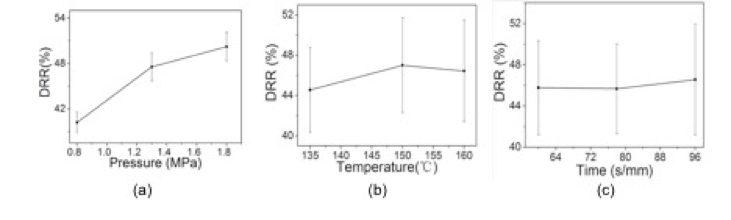
Fig. 5. Relationship between DRR and hot-press factors

Fig. 6. Micro distribution of carbon fiber in CFP
Figure 7 shows the micro distribution of the electric heating layers prepared under the different pressures of 0.8 MPa, 1.3 MPa, and 1.8 MPa. After curing, the MRAF coated the conductive network of the CFP firmly. As pressure increased, more opportunities for potential contact points in the network formed. Furthermore, the pressure caused a full adhesive permeation, forming an effective agglutination, which provided good laps with constant and strong adhesive force.

Fig. 7. Micro distribution of the electric heating layer
Figure 8 shows the trend of DRR in the hot-press process. At the pressures of 1.3 MPa and 1.8 MPa, DRR fell rapidly at the beginning of the pressurized stage. As the pressure reached pre-set pressure and 60 s later, the resistance began to exhibit slight variation, yet it needed more time to stabilize at the pressure of 0.8 MPa. As the process continued, the resistance tended to be stable. Finally, the resistance rebounded a small amount as the temperature dropped while cooling for 24 h. The pressure made more chopped carbon fibers overlap each other. When some carbon fibers slid into a closer position, more carbon fibers contacted each other, and the resistance decreased (Yuan and Fu 2014; Qiu et al. 2017). The decreased resistance remained in the pressure holding and unloading stage, which was further evidence that pressure played a decisive role in the resistance change.

Fig. 8. DRR during the process of hot press. H1 represents a third preset pressure, H2 represents two thirds of the preset pressure, H3 represents the preset pressure, H20~H380 represent stages of every 20s, and Hu represents the moment unloading, while Hc represents the state after it was left to cool for 24 h.
Influence of Different Composite Process on Bonding Performance
Table 4 shows the results of the bonding strength tests. It is worth noting that all bonding strengths were more than 1.8 MPa. The wood failure rate of specimens made under the pressures of 1.3 MPa and 1.8 MPa was desirable (approximately 100%), but specimens under 0.8 MPa had lower wood failure rate.
Table 4. Results of the Orthogonal Experiment

The R value of bonding strength in Table 4 shows that the pressure had a larger influence. As shown in Fig. 9a, the trend was almost flat after 1.3 MPa. There was little difference in bonding strength between 1.3 MPa and 1.8 MPa. Thus, the microstructure of the rip surface of the electric heating layer under the pressures of 0.8 MPa and 1.3 MPa, illustrated in Fig. 10, indicated that the layer under 1.3 MPa was denser. It was more likely to form interspaces among wood fiber and carbon fiber in the layer under 0.8 MPa due to the effect of pressure on the extent of permeation of MRAF into the wood fiber and carbon fiber. Figure 9b shows that its bonding strength was above 2.0 MPa under the temperature of 135 °C, but it could not be further improved as the temperature raising. The results could be attributed to that excessive temperature would shorten the time of the adhesive to melt and permeate in the electric heating layer. As another important factor for the solidification of adhesive, when hot-press time increased from 60 s/mm to 78 s/mm, a slight addition of the strength can be seen in Fig. 9c, which can be attributed to the more sufficient solidification of the MRAF.

Fig. 9. Relationship between bonding strength and hot-press factors

Fig. 10. Microstructure of rip surface in electric heating layer
The immersion-peel test results found that the 54 tested specimens were not disqualified. As shown in Fig. 11, the glue layer of the electric heating plywood substrate was not degummed. The electric heating layer was not degummed either, including the parts where electrodes were covered, indicating that the MRAF was suitable for gluing. In other words, pressures from 0.8 MPa to 1.8 MPa could not weaken the bonding strength of the glue layer in the electric heating plywood substrate.

Fig. 11. The result of immersion-peel tests of a specimen
Analysis of Capability of Insulation and Water Resistance of the Electric Heating Layer
Figure 12 shows the electric heating layer between two substrates. The thickness of the electric heating layer was about 0.15 mm, and it was about 0.2 mm (MRAF 0.06 mm + CFP 0.08 mm + MRAF 0.06 mm) before hot pressing. As shown in Fig. 7, the CFP was encapsulated by the MRAF and permeated fully by its adhesive, which enhanced the properties of insulation and water resistance due to the toughness, chemical resistance (El-Sayed et al. 2006), and electric insulation of the melamine resin (Liu 1988). Compared with the composite made with liquid adhesive by Yuan and Fu (2014), this plywood showed better insulation and water resistance. Also, the efficiency of the process was greatly improved by using half-solidified adhesive film during assembly.

Fig. 12. Micro cross section of the electric heating layer
Discussion and Determination of Optimal Composite Process
Through the comprehensive analysis of bonding performance and the DRR above, and in view of that the adhesion properties of plywood are related to the safety, the bonding performance should be the main factor considered.
The ideal value of hot-press pressure was 1.3 MPa because the specimens bonded under 0.8 MPa had lower performance on wood failure rate and bonding strength. The DRR and bonding strength increased by a small amount as specimens bonded under 1.8 MPa, but the higher pressure required more energy. Further, DRR tended to be relatively stable after 1.3 MPa, which indicates that the pressure in this range was beneficial in controlling power deviation.
The plate temperature and hot-press time were not very important to bonding strength and DRR. Thus, the plate temperature was set to 135 °C to minimize energy consumption. For hot-press time, 60 s/mm was ideal for enhancing the efficiency of practical production. Therefore, the final optimal composite process for the electric heating plywood was a hot-press pressure of 1.3 MPa, a plate temperature of 150 °C, and a hot-press time of 60 s/mm.
Time-temperature Property of The Electric Heating Plywood
Figure 13 shows that the temperature changed after a power density of 300 W/m2 was applied to the plywood. The surface of the plywood reached a stable TR of about 17 °C in 1800 s (0.57 °C /min) and the TR of the bottom was about16 °C in 1710 s (0.56 °C /min). The TR curves were similar. Both exhibited an exponential function relationship (surface Eq. (1); bottom Eq. (2) and correlation coefficient (R2)) with heating time, but the surface TR was slightly higher than that of the bottom even though it was the symmetrical structure.
y = 16.92 – 17.46 e-x/542.98 (R2 = 0.998) (1)
y = 15.87 – 16.47e-x/510.48 (R2 = 0.998) (2)

Fig. 13. Time-temperature property of the electric heating plywood
Figure 14 shows the surface temperature distribution of the electric heating plywood. The plywood temperature distribution had differences of about 6 °C, 6.5 °C, and 7.7 °C between maximum and minimum temperatures under the power densities of 300 W/m2, 500 W/m2, and 700 W/m2, respectively, in the central area (black dashed box area in Fig. 4). The temperature distribution under the commonly used power density of 300 W/m2 met the requirement of JG/T 286 (2010). However, the temperature distribution was less uneven than that of the composite described by Yuan and Fu (2014). The heterogeneous texture of the eucalyptus veneer, the thicker substrate, and larger reference area for calculating the unevenness contributed to the temperature distribution. The temperatures of electric heating plywood edges were lower than the temperatures of the central areas for the edges had a faster heat dissipation speed (Hua and Fu 1995).

Fig. 14. Three-dimensional equilibrium temperature distribution map (environment temperature about 22 °C)
Figure 15 shows the equilibrium TR under various power densities. As shown by the R2 value of 0.99 obtained with Eq. 3, the TR had a good linear relationship with power density, which was also reported by Yuan and Fu (2014). Figure 16 demonstrates that the change trend of TR under different power densities was similar in that the current first increased rapidly and later leveled off. A stable TR was achieved at about 30 min.
y = 1.48 + 0.05x (3)

Fig. 15. Relationship between power density and TR

Fig. 16. Relationship between heating time and TR with power densities for 2 h
Analysis of Resistance Stability in the Heating Process
The resistance of the electric heating plywood changed a small amount under a power density of 500 W/m2 for 24 h, as shown in Fig. 17. The resistance decreased as the heating time extended, but the maximum DRR was only 0.44% with a maximum TR difference of only 0.3 °C. The electric heating plywood using the half-solidified adhesive film as its gluing material had a better ability to control power, evidenced by its lower DRR value (i.e., better resistance (power) stability), than the composite prepared by Yuan and Fu (2014). Figure 18 shows that resistance declined before the 40th power cycle, and remained unchanged later, with the DRR at 1.25% when it was stable.
Based on the above microstructure in the electric heating layer, there was impure material on the surface of the carbon fiber. Also, there was cured adhesive in the conductive network, which could have formed a fragile interface with low conductivity between any two carbon fibers, hindering the movement of electrons in the conductive network. Under the synergistic effect of the electric field and heat field formed after power was applied, the fragile interface in the electric heating layer broke down (Yang et al. 2000), which increased conductive pathways. More pathways in the electric heating layer lead to better conductivity (Hung et al. 2015). Thus, the resistance decreased.

Fig. 17. Relationship between resistance and heating time

Fig. 18. Relationship between resistance and on-off times
CONCLUSIONS
- The orthogonal experiment results for plywood show that the pressure affected the permeation of the adhesive into the carbon fiber paper (CFP). The pressure was the main factor that affected the drop rate of resistance (DRR), bonding strength, and wood failure rate, with an improved bonding strength of above 1.8 MPa in this study. The optimal composite process was a hot-press pressure of 1.3 MPa, plate temperature of 150 °C, and hot-press time of 60 s/mm. DRR tended to be relatively stable after 1.3 MPa, which indicated that the pressure in this range was beneficial for controlling power deviation.
- The speed of heat transfer toward the surface of the plywood and the speed of heat transfer toward the bottom of the plywood were very similar. The central area had a uniform temperature distribution with a temperature difference of 6 °C under the commonly used power density of 300 W/m2. The temperatures of electric heating plywood edges were lower.
- The temperature rise (TR) of the surface and the TR of the bottom exhibited exponential relationships with heating time. The thermal resistance to the surface was lower than that to the bottom due to the fact that the TR of the surface was a bit higher than that of the bottom, which was favourable for effective heat utilization. The tendency of the TR under various power densities was similar. Further, the equilibrium temperature of the surface had a significant linear relationship with the power density.
- The electric heating plywood had good power stability as the maximum resistance changed by only 0.4% after overloading electricity for 24 h under a power density of 500 W/m2. The resistance was stable after the 40th power cycle, and the maximum DRR was 1.25% with 120 power cycles.
- Scanning electron microscope (SEM) analysis of the micro structure in the electric heating layer showed that using the plywood adopted melamine resin adhesive film (MRAF) as an adhesive would improve insulation and water resistance. This scheme offered a simple process for large-scale manufacture of the adopted MRAF, which exhibited good bonding performance and electric heating stability.
ACKNOWLEDGMENTS
The authors appreciate the support of the Scientific Research and Technology Development Project of Nanning (China) “Key Manufacturing Technology: Development and Promotion of a New-type of Electric Heating Functional Composite Fiberboard”, No. 20175030-2.
REFERENCES CITED
El-Sayed, W. S., El-Baz, A. F., and Othman, A. M. (2006). “Biodegradation of melamine formaldehyde by micrococcus, sp. strain mf-1 isolated from aminoplastic wastewater effluent,” International Biodeterioration and Biodegradation 57(2), 75-81. DOI: 10.1016/j.ibiod.2005.11.006
GB/T 18103 (2013). “Engineered wood for flooring,” Chinese National Standardization Management Committee, Beijing, China.
GB/T 9846 (2015). “Plywood for general use,” Chinese National Standardization Management Committee, Beijing, China.
Hua, Y. and Fu, F. (1995). “Studies on electrically conductive plywood,” Scientia Silvae Sinicae 31(3), 254-259.
Hung, C. J., Liu, C. H., Wang, C. H., Chen, W. H., Shen, C. W., Liang, H. C., and Ko, T. H. (2015). “Effect of conductive carbon material content and structure in carbon fiber paper made from carbon felt on the performance of a proton exchange membrane fuel cell,” Renewable Energy 78, 364-373. DOI: 10.1016/j.renene.2015.01.021
JG/T 286 (2010). “Electric radiant heating film for low temperature,” Ministry of Housing and Urban-Rural development of the People’s Republic of China, Beijing, China.
Li, J. L., Xue, P., He, H., Ding, W. Y., and Han, J. M. (2009). “Preparation and application effects of a novel form-stable phase change material as the thermal storage layer of an electric floor heating system,” Energy and Buildings 41(8), 871-880. DOI: 10.1016/j.enbuild.2009.03.009
Liu, Q. (1988). “Quality control and modification of melamine resin,” China Forestry Science and Technology (2), 18-20. DOI:10.13360/j.issn.1000-8101.1988.02.007
Lundstrom, F., Frogner, K., Wiberg, O., Cedell, T., and Andersson, M. (2017). “Induction heating of carbon fiber composites: Investigation of electric and thermal properties,” International Journal of Applied Electromagnetics and Mechanics 53(S1), S21-S30. DOI: 10.3233/JAE-162235
Ma, C., Liu, Y., Wang, D., and Liu, J. (2014). “Study on dynamic heat dissipation characteristics of low temperature hot water radiant floor,” Journal of Xi’an University of Architecture & Technology (Natural Science Edition) 46(3), 416-421, 488. DOI: 10.3969/j.issn.1006-7930.2014.03.020
Ma, X., Wei, X., Huang, B., and Yan, J. (2011). “The effect of conductive fillers on the performance of electric conductive ink used in electric radiant heating film,” Journal of Beijing Institute of Graphic Communication 19(2), 16-18. DOI: 10.3969/j.issn.1004-8626.2011.02.006
Qiu, D., Peng, L., Yi, P., and Lai, X. (2017). “A micro contact model for electrical contact resistance prediction between roughness surface and carbon fiber paper,” International Journal of Mechanical Sciences 124-125, 37-47. DOI: 10.1016/j.ijmecsci.2017.02.026
Seo, J., Jeon, J., Lee, J. H., and Kim, S. (2011). “Thermal performance analysis according to wood flooring structure for energy conservation in radiant floor heating systems,” Energy and Buildings43(8), 2039-2042. DOI: 10.1016/j.enbuild.2011.04.019
Song, J., Yuan, Q., Liu, X., Wang, D., Fu, F., and Yang, W. (2015). “Combination of nitrogen plasma modification and waterborne polyurethane treatment of carbon fiber paper used for electric heating of wood floors,” BioResources 10(3), 5820-5829. DOI: 10.15376/biores.10.3.5820-5829
Wang B. Q. (2012). “Electric heating material and laminate floor containing same and method for producing the laminate floor,” U. S. Patent 8304694.
Yang, X. P., Rong, H. M., and Lu, Z. D. (2000). “A study of the electrical properties of carbon fiber conductive composite,” Journal of Materials Engineering (9), 11-14. DOI: 10.3969/j.issn.1001-4381.2000.09.003
Yuan, Q., and Fu, F. (2014). “Application of carbon fiber paper in integrated wooden electric heating composite,” BioResources 9(3), 5662-5675. DOI: 10.15376/biores.9.3.5662-5675.
Yuan, Q., Liang, S., Zeng, Y., Wang, B., and Fu, F. (2015). “Discussion on technology status of electric heating wood and bamboo floor with built-in electrothermal layer,” China Forest Products Industry42(8), 6-9. DOI: 10.3969/j.issn.1001-5299.2015.08.002
Yuan, Q., Lu, K., and Fu, F. (2014). “Process and structure of electromagnetic shielding plywood composite laminated with carbon fiber paper,” The Open Materials Science Journal 8(1), 99-107. DOI: 10.2174/1874088X01408010099
Article submitted: July 15, 2017; Peer review completed: September 17, 2017; Revised version received and accepted: September 30, 2017; Published: October 11, 2017.
DOI: 10.15376/biores.12.4.8953-8969