
Abstract
Carbon fibers were pretreated by ultrasonic agitation and then were used to manufacture carbon fiber-reinforced wood composites (CFRWCs) . The modulus of rupture (MOR) and the modulus of elasticity (MOE) for the CFRWCs were measured. The effects of the compounding pattern and proportion of carbon fiber on the dynamic performance were investigated by dynamic thermomechanical analysis (DMA) and finite element analysis (FEA). Finite element modeling was performed to simulate composite dynamic analysis using ANSYS commercial software. DMA results showed that the critical parameters for the mixed boards appeared to initially increase and then decrease as the content of carbon fiber increased. ANSYS simulations showed that the first-order natural frequency increased for single-sided and two-sided boards as the composite’s carbon fiber content increased, whereas it initially increased and then decreased for mixed boards. In general, the mixed board with 20 wt.% carbon fiber had maximum dynamic performances. ANSYS simulation results were very close to those of the static test, which demonstrated that the finite element model was accurate.
Download PDF
Full Article
Dynamic Analysis of Carbon Fiber–Reinforced Wood Composites Based on Finite Element Model
Dongyan Zhang, Haiming Liu, and Liping Sun *
Carbon fibers were pretreated by ultrasonic agitation and then were used to manufacture carbon fiber-reinforced wood composites (CFRWCs). The modulus of rupture (MOR) and the modulus of elasticity (MOE) for the CFRWCs were measured. The effects of the compounding pattern and proportion of carbon fiber on the dynamic performance were investigated by dynamic thermomechanical analysis (DMA) and finite element analysis (FEA). Finite element modeling was performed to simulate composite dynamic analysis using ANSYS commercial software. DMA results showed that the critical parameters for the mixed boards appeared to initially increase and then decrease as the content of carbon fiber increased. ANSYS simulations showed that the first-order natural frequency increased for single-sided and two-sided boards as the composite’s carbon fiber content increased, whereas it initially increased and then decreased for mixed boards. In general, the mixed board with 20 wt.% carbon fiber had maximum dynamic performances. ANSYS simulation results were very close to those of the static test, which demonstrated that the finite element model was accurate.
Keywords: Carbon Fiber-Reinforced Wood Composites (CFRWCs); Finite element model;
Natural frequency; Dynamic analysis; Mechanical property
Contact information: College of Mechanical and Electrical Engineering, Northeast Forestry University, Harbin 150040 China; *Corresponding author: zdhslp@163.com
INTRODUCTION
With excellent physical and mechanical performance, such as high specific strength, specific modulus, and dimension stability, carbon fibers (CFs) are increasingly used with a variety of matrix materials to develop reinforced materials (Fuso et al. 2009; Liu et al. 2010), especially carbon fiber-reinforced wood composites (CFRWCs) (Hale and Bulent 2010; Zhang et al. 2011; Wei et al. 2013). The addition of carbon fiber not only maintains the natural properties of the wood, but also greatly improves the compressive strength and bending, which tremendously extends the product’s range of application. Research has mostly focused on the static performance of the CFRWCs; however, composite materials might be subject to negative effects from dynamic loads during use. When the vibration frequency from the excitation source is close to the natural frequency of the composite material, resonance is most likely to occur in the structure (Hou and Zheng 1997); this phenomenon can cause great damage to the system. Therefore, research into the dynamic performance of composite materials has important practical significance. Recently, researchers have been reporting progress regarding dynamic analysis for material. Shi and Luo (2011) reviewed the vibration performances of carbon fiber reinforced resin matrix and carbon matrix composites, and introduced the influence of fibers, matrix, fiber/matrix interface, and temperature on the vibration performance of carbon fiber reinforced composites in detail. Mlyniec et al. (2014) investigated the influence of laminate thickness, stacking sequence, and thermal aging on the damping behavior of carbon/epoxy laminates; the authors concluded that a mechanism of damping within composite structures mainly depended on the stacking sequence. Abo-Elkhier et al. (2014) employed natural frequency, damping ratio, and mode shape testing to predict the fatigue life of glass fiber-reinforced polyester composites; the authors’ experimental modal analysis results showed that damping ratio was a good indicator of the composite’s damping behavior.
From the above literature review, researchers mostly have employed experimental methods to study dynamic performances of composites (e.g., natural vibration frequency, damping, and mode shape). Nevertheless, computerized technological development has proceeded at an explosive pace, and computer aided engineering (CAE) technology is extending the research methods for composite materials. For instance, Song (2013) used finite element modal analysis in computer simulations to obtain modal information for composite unmanned aerial vehicles (UAV). Ji et al. (2011) predicted the structural performance of composite sandwich bridge decks with hybrid GFRP-steel core utilizing a finite element model simulated with ANSYS commercial software (ANSYS, Inc., USA).
Research on dynamic analysis for CFRWCs is relatively scarce, particularly using computer simulation. In the present study, in order to investigate the effects of compounding pattern and proportion of carbon fiber on dynamic performance for CFRWCs, carbon fibers were pretreated by ultrasonic agitation to prepare the specimens. Dynamic thermomechanical analysis (DMA) and finite element analysis (FEA) were employed as research methods. A finite element model was established to conduct dynamic analysis under the ANSYS environment. Meanwhile, the modulus of rupture (MOR) and modulus of elasticity (MOE) of CFRWCs were measured to verify the accuracy of computer simulation results.
EXPERIMENTAL
Materials
Raw materials
The short-cut carbon fiber was purchased from Jilin JiYan High-tech Fibers Co., China. Its purity, density, and length were 96.0%, 1.76 g/cm3, and 5 mm, respectively. The tensile strength and tensile modulus were 3.0 GPa and 310 GPa, respectively. Fresh poplar fiber was obtained from a Heilongjiang Xinglong-town medium density fiberboard (MDF) factory; the length and moisture content of the poplar fibers was 3 mm and 5%, respectively.
Adhesive
Urea-formaldehyde (UF) resin was used as the adhesive and was obtained from Shenyang W&Y Express Trading, China. The solid content, pH and density for the UF resin were 55%, 8.8 and 1.31 kg/m3, respectively. UF resin was 12 wt.% of the fresh poplar fiber.
Chemicals
The acetone/isocyanate resin and wheat flour as a filling agent were added to UF resin. The ammonium chloride was used as a curing agent, diluted using distilled water and added to UF resin. The anhydrous ethanol is a dispersing agent used to disperse the CFs.
Experimental Design
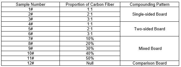
Three compounding patterns were utilized to enhance MDF, including single-sided board, two-sided board, and mixed board. The single-sided board and two-sided board were prepared as a surface enhancement, and the mixed board was prepared as a volume enhancement. The mass ratio of carbon fiber-to-wood fiber for surface enhancement were 1-to-1, 2-to-1 and 3-to-1. The mass ratio of carbon fiber to wood fiber for volume enhancement were 10 wt.%, 20 wt.%, 30 wt.%, 40 wt.%, and 50 wt.%. MDF without carbon fiber was prepared for comparison using 1000 g of wood fiber.
Methods
Pretreatment of carbon fiber
Carbon fibers were treated in an ultrasonic agitation device from Kunshan Ultrasonic Instruments Co., Ltd. (Model KQ-100DB) for 10 min. to prevent fiber agglomeration. Anhydrous ethanol was used as a dispersing agent. Afterwards, the carbon fibers were dried at 100 °C in a thermal drying oven from Shanghai Boxun Industry and Commerce Co., Ltd. (Model 9140MBE). To some extent, the process decreased agglomeration phenomenon and the effect mainly depended on carbon fiber content and processing time. Contrasting digital photos are given in Fig. 1.
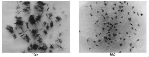
Fig. 1. Contrasting digital photos before and after pretreatment for CFs. 1(a) before; 1(b) after
Glue mixing
Wheat flour and acetone/isocyanate resin solution were added to UF resin to enhance the adhesive strength since the UF resin has a low molecular weight and viscosity (Gu et al. 2009). The wheat flour and isocyanate resin content were 1 wt.% and 10 wt.% of the UF resin, respectively, and the mass ratio of acetone-to-isocyanate resin was 2-to-1. Ammonium chloride, diluted to 20 wt.% using distilled water, was added to the UF resin in order to accelerate the curing time. Ammonium chloride solution was 5 wt.% of the UF resin.
Preparation for CFRWCs
The wood fiber and treated carbon fiber were placed into a blender and mixed at a speed of 1200 rpm for 30 min to obtain a homogenous mixture. Meanwhile, the compound adhesive was sprayed into a blender at a constant speed by a spray gun. Because the core layer consisted only of wood fiber for single-sided and two-sided boards, the wood fiber in the core layer was separately processed by stirring and gluing. Afterwards, according to different compounding patterns, wood fiber and carbon fiber with adhesive were laid down into a mold with the cross section of 420 mm by 420 mm. Schematic diagrams for different compounding patterns are given in Fig. 2.
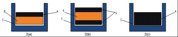
Fig. 2. Schematic diagrams for different compounding patterns: 2(a) single-sided board; 2(b) two-sided board; and 2(c) mixed board. A consists of carbon fiber and wood fiber, and B consists of wood fiber. C denotes a mold. The light orange denotes the core layer.
The materials were pre-pressed at 1.6 MPa pressure for 5 min to increase the initial bonding strength between carbon and wood fibers. Afterwards, the pre-pressed panels were hot-pressed at 165 °C for 6 min. 18 MPa pressure was applied for the first 2 min, and 5 MPa pressure was applied for the remaining time, which contributed to excluding excess water within the panels (Li 2001) with a nominal thickness of 11 mm. Eventually, specimens were cooled for 24 h. Images and nomenclature for all specimens are given in Fig. 3 and Table 1.

Fig. 3. Images for all specimens: 3(a), 3(b) and 3(c) were single-sided boards; 3(d), 3(e) and 3(f) were two-sided boards; 3(g), 3(h), 3(i), 3(j), and 3(k) were mixed boards; 3(l) was MDF without carbon fiber. CF and WF represented carbon fiber mass and wood fiber mass, respectively.
Table 1. Nomenclature of Samples
Measurements
Preparation for test samples
The sample dimension for MOR and MOE testing was 270 mm × 50 mm × 11 mm, and the sample dimension for DMA testing was 45 mm × 15 mm × 5 mm. Three samples were prepared from each specimen for MOR, MOE, and DMA statistical analysis. All test samples were placed in a conditioning chamber (temperature of 20 ± 2 °C and relative humidity of 65 ± 5%) until the sample mass remained constant.
Measurements of MOR and MOE
Static testing was conducted with a universal mechanical instrument from Shimadzu (Model AG-10TA, Japan) using the three-point bending method in accordance to the wood-based panel standard GB/T11718-2009 (China). The span was 220 mm between the two support rollers. Loading roller speed was 15 mm/min. until the samples failed. MOR and MOE were calculated by Equations (1) and (2), respectively,
![]() (1)
(1)
![]() (2)
(2)
where is the modulus of rupture (MPa), is the maximum load (N), is the span between the two support rollers (mm), is the cross sectional width (mm), is the cross sectional thickness (mm), is the modulus of elasticity (MPa), is the force increment in a straight line segment for the load-deflection curve (N), and is the deformation increment (mm).
Measurements of dynamic modulus
The DMA test in three-point bending mode was conducted with a dynamic mechanical analyzer DMA242 (NETZSCH, Germany); it was operated at a temperature range from 25 °C to 300 °C with a constant heating rate of 5 °C/min and a test frequency of 1 Hz.
During the DMA test, a dynamic sinusoidal stress load was applied to the samples, which was defined as,
![]() (3)
(3)
where is the dynamic stress (MPa), is the stress amplitude (MPa), is the angular velocity (rad/s), and is the test frequency (Hz).
From known viscoelastic theory (Guo 2002), the strain lags behind the stress. Therefore, the corresponding strain for a is defined as,
![]() (4)
(4)
where is the dynamic strain, is the strain amplitude, is the angular velocity (rad/s), and (rad) is the phase difference between the stress and strain.
The dynamic modulus is defined as (Han et al. 2012; Yang 2007),
![]() (5)
(5)
![]() (6)
(6)
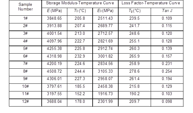
where is the dynamic modulus (MPa), is the absolute value of the amplitude (MPa), is the storage modulus (MPa), is the loss modulus (MPa), and is the loss factor. The storage modulus-temperature curve and loss factor-temperature curve were obtained from the data collected by the dynamic mechanical analyzer. Five critical parameters were obtained from two above-mentioned curves, including: storage modulus (E; at T = 25 °C); starting-point temperature (T0) and corresponding storage modulus (E0) at T0; glass transition temperature (Tg); and loss factor (tan d).
Finite Element Modeling
A commercial finite element method (FEM) modeling software (ANSYS, Inc., Canonsburg, PA, USA; version 12.0) was employed to investigate the effects of the compounding pattern and proportion of carbon fiber on the dynamic performance for the CFRWCs by simulation and natural frequency was obtained for all samples via the modal analysis method. The comparison between simulation and static mechanical tests were conducted to verify the veracity of simulation results. A first-order modal analysis was carried out. Modal extracting method was by the subspace method, and frequency range was from 1 Hz to 10 Hz.
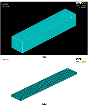
Fig. 4. Geometric model for a representative volume unit. a: The cuboid and the embedded cylinder represent wood fiber and carbon fiber, respectively; b: Finite element model for CFRWCs
In order to reflect the different proportions of carbon fiber, the representative volume unit (unit cell model) was established from the perspective of mesomechanics, which consisted of a cuboid and embedded cylinder, as shown in Fig. 4(a). According to density and geometric volume for each material, the different proportions of carbon fiber were realized by conversion.
The compounding patterns were realized by an entity geometry model and a Boolean operation. It was seen from the actual samples that a cover layer (as shown A in Fig. 2a and b) for single-sided and two-sided boards was moderately thin, so SHELL 181 as element type was used, whose attributes (modulus of elasticity, Poisson ratio and density) were set according to Mori-Tanaka method (Benveniste 1987; Christensen 1990; Chen 2008). Meanwhile, the SOLID 183 as element type was used for the core layer and mixed board (Fig. 2). Because the core layer only consisted of the wood fiber, the above-mentioned attributes were set according to material provider. The linear and isotropic material properties were defined. The finite element model is given in Fig. 4(b).
RESULTS AND DISCUSSION
Static Test Analysis
As shown in Table 2, the MOR and MOE for common MDF was generally enhanced by the addition of carbon fiber, which was consistent with other research reports (Shi 2011; Zhu and Sun 2015). However, the compounding pattern and the proportion of carbon fiber had noteworthy effects on the material’s static performance.
Table 2. Data Contrast for MOR and MOE
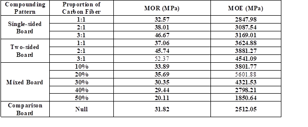
As the carbon fiber content was increased, the MOR for single-sided and two-sided boards increased. When the proportions of carbon fiber were identical, the two-sided board was superior to the single-sided board. The main reason for this is as follows. During static test, the surface against the loading roller was subjected to compressive stress and the other surface was subjected to tensile stress, the addition of carbon fiber with excellent mechanical properties enhanced the compressive and tensile strength of CF-reinforced composite (He 2010). MOR for mixed boards had no obvious difference when the proportion of carbon fiber was increased from 10 wt.% to 40 wt.%, which is consistent with another research report (Khan et al. 2013). However, the MOR decreased rapidly for a sample with 50 wt.% carbon fiber; the reason for this observation may be due to the agglomeration of carbon fibers within the composite matrix. On the whole, the MOR value for two-sided board with 3-to-1 carbon-to-wood fibers (6#) was maximum, which was 52.37 MPa; it was 64.6% higher than the MOR value of the MDF board.
As the carbon fiber content was increased in the composites, the MOE values for both single-sided board and two-sided board appeared to increase with the trend of the two-sided board being more distinct than that of the single-sided board. When the proportion of carbon fiber was identical, the two-sided board was superior to the single-sided board. The MOE for the mixed board appeared to initially increase and then decrease with the turning point when CF content reached 20 wt.%. On the whole, the MOE value for the mixed board with 20 wt.% carbon fibers (8#) was maximum, which was 5601.88 MPa; it was 123% higher than the MOE value of the MDF board.
Dynamic Mechanical Analysis (DMA)
During the DMA test, the samples, which are subjected to alternating force, store mechanical energy in the form of potential energy when generating elastic deformation. Storage modulus is defined to characterize the ability for stored energy; it reflects the elasticity of composite materials (Liu 2014). As the temperature is increased, the internal molecular structure of the material is substantially changed. The starting-point temperature was defined as the temperature at which the samples started to transform from a glassy state to an elastomeric state.
It can be seen from Table 3 that the trend of E values mirrored that of the MOE values at 25 °C, and the reason for that might be that dynamic performance was, to some extent, related to static performance (Hu 2004). When the temperature reached T0, the E0 value was lower than the E value for all samples. The lower E0 was attributed to the phenomenon that the structures, which are smaller than chain segment, start to move when composite materials are in the glassy state with excellent elasticity. Afterwards, the elastomeric state is vastly inferior to the glassy state due to chain segment motion (Qin et al. 2012). In the case of the same compounding pattern, as the carbon fiber content was increased, both T0 and E0 appeared to increase for single-sided and two-sided boards, whereas T0 and E0 appeared to initially increase and then decrease for mixed board. In the case of the same proportion of carbon fiber, the two-sided board exhibited higher E, E0 and Tg values than the single-sided board. On the whole, the mixed board with 20 wt.% carbon fiber had maximum T0 and storage modulus; these dynamic properties decreased as the proportion of carbon fiber was increased to 30 wt.% or higher.
Glass transition temperature (Tg) is the intrinsic quality of amorphous polymer materials and the macroscopic reflect of motion form for macromolecule; it directly affects usability and processing property for materials. When the temperature reached the Tg, the samples were completely in an elastomeric state. The trend of Tg was the same as that of T0, which increased the temperature range of the glassy state and contributed to extending potential fields of application for CFRWCs used in structural engineering. Tan d quantifies the damping characteristic for materials as defined by Eq. 6; the larger the tan d value is, the higher the dampening and noise reduction capacity of the composite are. As shown in Table 3, the addition of carbon fiber enhanced the damping performance when compared with MDF. When the carbon fiber content was increased, the loss factor appeared to increase for single-sided and two-sided boards, but the two trends were not distinct. In the case of the same proportion of carbon fibers, the two-sided board was larger than the single-sided board in quantitative terms. The mixed boards’ tan d values appeared to initially increase and then decrease as the carbon fiber level was increased; the maximum tan d value, 0.254, was obtained for mixed board made with 20 wt.% carbon fiber (8#). This tan d value was 159% higher than that of the MDF board.
Table 3. Crucial Parameter Data Extracted from DMA Curves
Finite Element Simulation Analysis
As shown in Fig. 5 and Table 4, the deformation and maximum displacement for composite board samples that contained carbon fiber was lower than that of the MDF board when compared at the same applied external force. Considering that the MOR is an indicator of bending resistance, so the addition of carbon fiber enhanced MOR for CFRWCs, which agreed with the static test result. According to the geometric equation about displacement-strain relation (Xu 2006), the decrease of displacement will cause that of strain; additionally, the same external stress was applied to all samples to ensure uniform experimental condition. Therefore, MOE increased according to the definition of MOE, which also agreed with the static test result. As shown in Table 4, as the carbon fiber content was increased, the maximum displacement for single-sided and two-sided boards appeared to decrease, whereas the mixed board initially decreased and then increased, which was also in accordance with the MOE data. The above results indicate that the finite element model was accurate and feasible.
It was noteworthy that the simulation data were inconsistent with the static test data for 11#. The main reason for this is as follows: the discussional circumstances were different, simulation was implemented under conditions where distribution was homogeneous between the reinforcement phase and matrix phase. According to the concept of a crowding factor (Kerekes and Schell 1992), high carbon fiber content most likely induces the agglomeration phenomenon for 11# in practice; the shorter active time for ultrasonic agitation may be the reason for this (Han et al. 2009). However, a special case did not affect the overall conclusion.
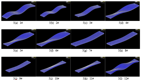
Fig. 5. The deformation figures for all samples by first-order modal analysis
Table 4. First-Order Natural Frequency and Maximum Displacement Data
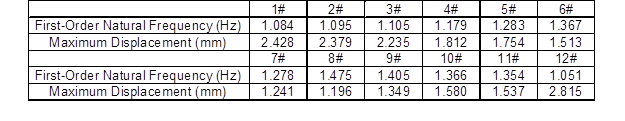
It can be seen from Table 4 that the addition of carbon fiber enhanced the first-order natural frequency for the CFRWCs. As the carbon fiber content was increased, the first-order natural frequency for single-sided and two-sided boards appeared to increase, whereas the mixed board initially increased and then decreased. When the proportion of carbon fiber was identical, the two-sided board was larger than the single-sided board in quantitative terms. On the whole, the mixed board was larger than the other two boards in quantitative terms; the maximum first-order natural frequency value, 1.475 Hz, was obtained for mixed board made with 20 wt.% carbon fiber (8#). This value was 40% higher than that of the MDF board.
CONCLUSIONS
- The addition of carbon fiber to composites had an apparent influence on the dynamic performances of CFRWCs. As the proportion of carbon fiber was increased from 1:1 to 3:1, the storage modulus, starting-point temperature and glass transition temperature all appeared to increase for single-sided and two-sided boards, whereas the loss factor indistinctly increased. When the proportion of carbon fiber was increased from 10 wt.% to 50 wt.% for the mixed board, the above dynamic parameters appeared to initially increase and then decrease. Overall, the mixed board with 20 wt.% carbon fiber had maximum dynamic performance.
- The addition of carbon fiber to composites had an apparent influence on the first-order natural frequency. As the proportion of carbon fiber was increased from 1:1 to 3:1, the first-order natural frequency for single-sided and two-sided boards appeared to increase, whereas the mixed board appeared to initially increase and then decrease. When the proportion of carbon fiber was identical, the two-sided board was larger than the single-sided board in quantitative terms. Overall, the mixed board was larger than the other two boards in quantitative terms.
- Although carbon fiber agglomeration occurred for 11# (50 wt.% carbon fiber), the ANSYS simulation results were in accordance with those of the static test for the other samples, which demonstrated that the finite element model was accurate.
- The two-sided and mixed boards had a unique advantage in enhancing the MOR and MOE, respectively.
ACKNOWLEDGMENTS
The authors are grateful for the support of the Fundamental Research Funds for the Central Universities (DL12CB06), and the Heilongjiang Provincial Foundation for Returned Overseas Chinese Scholars (LC201408).
REFERENCES CITED
Abo-Elkhier, M., Hamada, A. A., and Bahei El-Deen, A. (2014). “Prediction of fatigue life of glass fiber reinforced polyester composites using modal testing,” Int. J. Fatigue 69(Dec 2014), 28-35. DOI: 10.1016/j.ijfatigue.2012.10.002
Benveniste, Y. (1987). “A new approach to the application of Mori-Tanaka’s theory in composite materials,” Mech. Mater. 6(2), 147-157. DOI: 10.1016/0167-6636(87)90005-6
Chen, J. (2008). “Numerical prediction research on elastic mechanics characteristic for composites,” Master’s Thesis, University of Electronic Science and Technology of China, Chengdu, China.
Christensen, R. M. (1990). “A critical evaluation for a class of micromechanics models,” J. Mech. Phys. Solids. 38(3), 379-404. DOI:10.1016/0022-5096(90)90005-O
Fuso, L., Manfredi, D., Biamino, S., Pavese, M., Fino, P., and Badini, C. (2009). “SiC-based multilayered composites containing short carbon fibres obtained by tape casting,” Compos. Sci. Technol. 69(11-12), 1772-1776. DOI: 10.1016/j.compscitech.2008.07.001
Gu, J. Y., Hu, Y. C., and Zhu, L. B. (2009). “Production’s raw materials for wood-based panel,” in: Textbook of Production Technology and Application for Wood-Based Panel, Gu, J. Y., Hu, Y. C., and Zhu, L. B(ed.), Chemical Industry Press, Beijing, pg. 24.
Guo, M. L. (2002). “The basis of dynamic mechanical thermal analysis,” in: Textbook of Dynamic Mechanical Thermal Analysis of Polymer and Composite Materials, Guo, M. L. (ed.), Chemical Industry Press, Beijing, pg. 24.
Hale, G., and Bulent, A. (2010). “The effect of the wrapped carbon fiber reinforced polymer material on fir and pine woods,” Materials and Design 31(7), 3564-3567. DOI: 10.1016/j.matdes.2010.02.031
Han, B. G., Guan, X. C., and Ou, J. P. (2009). “Application of ultrasound for preparation of carbon fiber cement-based composites,” Mater. Sci. Technol. 17(3), 368-372.
Han, B. K., Zhang, T. T., and Cao, S. M. (2012). “Measurement and analysis of the dynamic modulus of polymer materials based on fractional model,” Noise Vib. Control 2012(5), 198-200.
He, F. (2010). “The properties of carbon fibre and graphite fibre,” in: Textbook of Carbon Fibre and Graphite Fibre, F. He(ed.), Chemical Industry Press, Beijing, pg. 392-393, 406.
Hou, Z. C., and Zheng, Z. C. (1997). “On the conditions for linear systems to avoid resonance,” J. Vib. Shock 16(3), 15-17. DOI: 10.13465/j.cnki.jvs.1997.03.003
Hu, Y. C. (2004). A Study on Dynamic Properties of Wood-Based Composites, Doctor’s Dissertation, Northeast Forestry University, Harbin, China.
Ji, H. S., Byun, J. K., Lee, C. S., Son, B. J, and John Ma, Z. (2011). “Structural performance of composite sandwich bridge decks with hybrid GFRP–steel core,” Compos. Struct. 93(Jan. 2011), 430-442. DOI: 10.1016/j.compstruct.2010.08.037
Kerekes, R. J., and Schell, C. J. (1992). “Characterization of fibre flocculation regimes by a crowding factor,” Journal of Pulp and Paper Science 18(1), 32-38.
Khan, T. A., Gupta, A., Jamari, S. S., Jose, R., Nasir, M., and Kumar, A. (2013). “Synthesis and characterization of carbon fibers and their application in wood composites,” BioResources 8(3), 4171-4184. DOI: 10.15376/biores.8.3.4171-4184
Li, C. Q. (2001). “Discussion on the technology of automatic hot pressing in MDF line,” Wood Processing Machinery 12(4), 21-22. DOI: 10.13594/j.cnki.mcjgjx.2001.04.007
Liu, P. Y (2014) Study on the Dynamic Viscoelasticity of Wood-Plastic Composites, Master’s Thesis, Zhejiang A & F University, Zhejiang, China.
Liu, Z. G., Mang, X. B., Chai, L. H., and Chen, Y. Y. (2010). “Interface study of carbon fibre reinforced Al–Cu composites,” J. Alloys Compd. 504(Supp. 1), S512-S514. DOI: 10.1016/j.jallcom.2010.04.081
Mlyniec, A., Korta, J., Kudelski, R., and Uhl, T. (2014). “The influence of the laminate thickness, stacking sequence and thermal aging on the static and dynamic behavior of carbon/epoxy composites,” Compos. Struct. 118(Dec. 2014), 208-216. DOI: 10.1016/j.compstruct.2014.07.047
Qin, D. K., Zhou, G. L., and Jin, J. F. (2012). “Effect of dynamic mechanical analysis on structure and properties of cyanate ester resin and its composite,” Mater. Mech. Eng. 36(8), 10-13.
Shi, F., and Luo, R. Y. (2011). “Research progress of vibration performances of carbon fiber reinforced composites,” Carbon Technol. 30(3), 35-39. DOI: 10.14078/j.cnki.1001-3741.2011.03.016
Shi, G. W. (2011). Carbon Fiber Composites of Mechanical and Electrical Properties Based on Finite Element, Master’s Thesis, Northeast Forestry University, Harbin, China.
Song, X. B. (2013). Dynamic Analysis of Composite UAV, Master’s Thesis, University of Chinese Academy of Sciences, Beijing, China.
Wei, P. X., Wang, J. H., Zhou, D. G., Dai, C. P., Wang, Q. Z., and Huang, S. W. (2013). “Mechanical properties of poplar laminated veneer lumber modified by carbon fiber reinforced polymer,” BioResources 8(4), 4883-4898. DOI: 10.15376/biores.8.4.4883-4898
Xu, Z. L. (2006). “The fundamental theory for spatial question,” in: Textbook of Elasticity, Xu, Z. L. (ed.), Higher Education Press, Beijing, p. 197.
Yang, M. (2007). Research on the Dynamic Modulus of Asphalt Mixtures, Master’s Thesis, Changsha University of Science and Technology, Changsha, China.
Zhang, D. Y., Gui, H. J., Sun, L. P., and Shi, G. W. (2011). “Numerical analysis of electrical conductivity of short carbon fiber reinforced wood,” Journal of Northeast Forestry University 39(2), 109-111. DOI: 10.13759/j.cnki.dlxb.2011.02.033
Zhu, X. L., and Sun, L. P. (2015). “Multiscale analysis on electrical properties of carbon fiber-reinforced wood composites,” BioResources 10(2), 2392-2405. DOI: 10.15376/biores.10.2.2392-2405
Article submitted: June 5, 2015; Peer review completed: September 19, 2015; Revisions received and accepted: November 5, 2015; Published: November 23, 2015.
DOI: 10.15376/biores.11.1.545-557