
Abstract
A commercial woodcutting circular sawblade was analysed in this work. The lateral stiffness on the periphery was measured, and the natural frequencies were determined by modal analyses. The sawblade was modelled by the finite element method, where the influence of the internal stresses caused by roll-tensioning of the sawblade was considered. The roll-tensioning force was determined based on the measurement of the sawblade rolling profile, where it was established that the sawblade had been rolled with a force of 7800 N. The analysis showed that at the aforementioned force, the lateral stiffness was a maximum; here, the calculated and measured stiffnesses were 81 and 60 N/mm, respectively. The calculated natural frequencies agree well with the measured ones, where in the most important vibrational modes there is only a 7% difference. The maximum rotational speed for the sawblade was determined to be 85% of the critical speed. Because the sawblade was clamped with a ratio of clamping of only 0.25, the maximum rotational speed was amounted to 6630 rpm. Increasing the rolling force would increase the critical speed but greatly reduce the lateral stiffness.
Download PDF
Full Article
Dynamic Behaviour Analysis of a Commercial Roll-Tensioned Circular Sawblade
Miran Merhar,a,* Dominika Gornik Bučar,a and Tomaž Pepelnjak b
A commercial woodcutting circular sawblade was analysed in this work. The lateral stiffness on the periphery was measured, and the natural frequencies were determined by modal analyses. The sawblade was modelled by the finite element method, where the influence of the internal stresses caused by roll-tensioning of the sawblade was considered. The roll-tensioning force was determined based on the measurement of the sawblade rolling profile, where it was established that the sawblade had been rolled with a force of 7800 N. The analysis showed that at the aforementioned force, the lateral stiffness was a maximum; here, the calculated and measured stiffnesses were 81 and 60 N/mm, respectively. The calculated natural frequencies agree well with the measured ones, where in the most important vibrational modes there is only a 7% difference. The maximum rotational speed for the sawblade was determined to be 85% of the critical speed. Because the sawblade was clamped with a ratio of clamping of only 0.25, the maximum rotational speed was amounted to 6630 rpm. Increasing the rolling force would increase the critical speed but greatly reduce the lateral stiffness.
Keywords: Circular sawblade; Roll-tensioning; Critical speed; Natural frequency; Vibration; Finite element method
Contact information: a: University of Ljubljana, Biotechnical Faculty, Department of Wood Science and Technology, Jamnikarjeva 101, SI-1000 Ljubljana, Slovenia; b: University of Ljubljana, Faculty of Mechanical Engineering, Aškerčeva cesta 6, SI-1000 Ljubljana, Slovenia;
* Corresponding author: miran.merhar@bf.uni-lj.si
INTRODUCTION
The circular sawblade is one of the most frequently used tools in the woodworking industry, where in a typical sawmill operation, approximately 12% of the wood is converted to sawdust. A further 7% of the wood is lost during planing of poor-quality sawn surfaces (Schajer and Mote 1983). The quality and thickness of the cut are in inverse proportion, as a thinner sawblade is less stable, which means the cut surface is of lower quality.
During the working process, the sawblade always vibrates transversely; however, its vibration is typically quite stable. However, in unstable conditions, it is possible that even a small disturbance will cause vibrations with large amplitudes. Because the instability highlights the negative aspects of vibrations, much research has been carried out to determine the mechanism of instability (Ellis and Mote 1978; Radcliffe and Mote 1981; Leu and Mote 1984; Schajer 1986; Holøyen 1987; Yu and Mote 1987; Hutton 1991; Beljo–Lučič and Goglia 2001). Some of these studies have focused on the effects of temperature on stability (Mote and Nieh 1973), while others have focused on the geometry of the sawblade (Mote and Szymani 1977; Szymani and Mote 1977).
A special form of instability, which is particularly important, is the critical speed of the circular sawblade, which was introduced in 1959 by Lapin and in 1966 by Dugdale (Mote and Szymani 1977). The theory was first used 50 years earlier in turbines (Mote and Szymani 1977), but from 1966 until now, the theory has developed to the point where the experimental critical speed corresponds to that which is theoretically calculated. The critical speed can be increased by increasing the sawblade’s natural frequency, which can be achieved in different ways, one of them being with the stress gradient in the sawblade. More than a hundred years ago, experienced craftsmen induced stress in the sawblade by hammering the saw in a manner learnt through experience, whereas today, the sawblade is rolled between two rollers (Szymani and Mote 1974; Schajer and Mote 1983, 1984; Stakhiev 1999, 2003). Besides increasing the natural frequencies, the lateral stiffness of the sawblade is also important (Stakhiev 1998), where Stakhiev (2000, 2004) states that on the sawblade periphery, the lateral stiffness should be at least 40 and 25 N/mm for longitudinal and cross cutting, respectively.
In addition to the most widely used symmetrical tensioning of circular sawblades with two rollers, there is also the less common asymmetrical tensioning by introducing pressure on the side surfaces of holes drilled in the sawblade (Parker and Mote 1989; Li et al. 2015a), with asymmetrical rolling or with a temperature gradient (Ishihara et al. 2010; Yuan 2012; Zhang et al. 2014; Li et al. 2015b).
In more recent times, with the emerging of the finite element method, many new designs of circular sawblades have been developed (Yuan 2012; Wasielewski et al. 2012; Droba et al. 2015; Kaczmarek et al. 2016a), and the influence of the rolling and geometrical parameters on dynamic behaviour has been calculated (Cristovao et al. 2012; Heisel et al. 2015; Li et al. 2016). Many new methods have also been developed for the verification of dynamic behaviour (Orlowski et al. 2007; Vesely et al. 2012; Kaczmarek et al. 2016b; Skoblar et al. 2016).
Manufacturers are obliged to state on the sawblade the maximum rotational speed, which is based on the reference rate of 85% of the lowest critical speed (Stakhiev 1999). The purpose of this study is to determine the maximum rotational speed for a commercial sawblade, available on the market, where no data about rolling conditions are known. Based on the modal analysis of the circular sawblade and with reference to the rolling effect, the actual critical speed of the blade will be calculated. The article will also present the method of determining the rolling force based on the rolling profile.
EXPERIMENTAL
Materials
Two woodcutting circular sawblades from a commercial producer (Fig. 1) were acquired, with a diameter of 300 mm, bore diameter of 30 mm, and thickness of 2.2 mm. The sawblades were roll-tensioned and had 96 carbide teeth and 4 radial slots with a length of 29 mm. The sawblades were made from 75Cr1 steel. To determine the mechanical properties of the steel, two testing specimens were made from one sawblade and testing was carried out according to the ISO 6892-1 (2016) standard. The testing samples (Fig. 2) were cut with a water jet to avoid thermal effects.
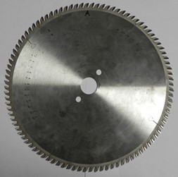
Fig. 1. The tested sawblade
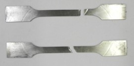
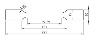
Fig. 2. The specimens for determination of the mechanical properties of 75Cr1 steel
Methods
Experimental
The sawblades tested were designed for transverse cutting of solid wood and wood-based materials and can be mounted on an ordinary table sawing machine, where the diameter of the flanges is usually 75 mm. To obtain the most realistic natural frequencies, the sawblade was mounted on an experimental system with flanges having a diameter of 75 mm. The sawblade was excited with a hammer, and the response was measured with an inductive displacement sensor type CARLO GAVAZZI IA12ASC05AK-K (Milano, Italy). The data were acquired at a sampling frequency of 30 kHz with a data acquisition card NI6351 and LabView software manufactured by National Instruments (Austin, TX). The time signal was then converted into a frequency spectrum by a fast Fourier transformation. With the described pulse excitation of the sawblade, many different vibration modes were excited at the same time. Because the sawblade was at a standstill, the forward and backward travelling wave of a particular mode had the same frequency. To determine which natural frequency belongs to which mode, the sawblade was rotated at a rotational speed of 3 Hz and hit again. Because the inductive displacement sensor was stationary, the detected higher frequency of the forward travelling wave and the lower frequency of the backward travelling wave can be used to calculate to which mode n they belong, using Eq. 1 (Mote and Szymani 1977),
 (1)
(1)
where m and n are the nodal circle and nodal diameter, respectively; ![]() and
and ![]() are the natural frequencies (Hz) of the forward and backward travelling waves, respectively, belonging to the vibration mode with m and n nodal circles and diameters, respectively; and νrot is the rotational speed (Hz).
are the natural frequencies (Hz) of the forward and backward travelling waves, respectively, belonging to the vibration mode with m and n nodal circles and diameters, respectively; and νrot is the rotational speed (Hz).
To determine the sawblade’s lateral stiffness, the saw was peripherally loaded with a force of 40 N and the deformation was measured with an inductive displacement transducer.
Because the sawblade was roll-tensioned to increase the lateral stiffness and natural frequencies, the rolling force has first to be determined. To accomplish this, the transverse profile of the rolling area was measured at different locations with a laser type MICRO-EPSILON LD1605-0.5 (Ortenburg, Germany), which was mounted on a linear guide and driven by a servo motor via a screw spindle. The shape and depth of the profile was then used to determine the crown radius of the roller and the force with which the sawblade was rolled, in the manner described below.
Finite element method
The sawblade was modelled with the finite element method (FEM), using Abaqus (Vélizy-Villacoublay Cedex, France) software (Fig. 3).
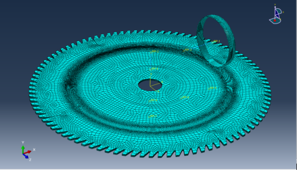
Fig. 3. The circular sawblade finite element model
The data for the modulus of elasticity, plastic deformation, and stress were used from the tensile test, while the density was measured from the sawblade and amounted to 7910 kg/m3. The value of 0.3 was taken as the value for the Poisson ratio. First, the sawblade rolling was modelled, where the rolling radius was taken from the experimental sawblade and amounted to 100 mm, while the roller used for tensioning had a crown and a roll radius of 12.5 mm and 35 mm, respectively, where the crown radius was determined from the shape of the rolling profile. Because the roller was modelled as a rigid body, only the rolling surface of the roller was modelled. The sawblade had 5 linear elements through its thickness, where the size of the elements ranged from 0.1 mm in the rolling area up to several millimetres on the rest of the sawblade. This model contained approximately 350,000 elements. The sawblade was rigidly clamped at a diameter of 75 mm and rolled with forces of 3.4, 5.5, 7.8, 10.1, 12.9, 15.5, and 18.3 kN. The value of 0.1 was taken for the coefficient of friction, as reported by Heisel et al. (2015). After the rolling process, the sawblade clamping was released, so that the internal stress was distributed across the whole sawblade. After that, the calculated rolling profile was compared to the measured one to determine the actual rolling force and roller crown radius.
To calculate the natural frequencies of the sawblade, FEM modal analysis was performed, where the sawblade with built-in internal stresses caused by rolling was clamped with a flange diameter of 75 mm.
First, the natural frequencies of the stationary sawblade were calculated; then, the calculation was repeated with incorporated additional internal stresses caused by rotation, where the sawblade rotated with a rotating speed of 100 Hz. In the latter case, the natural frequencies of the rotating sawblade were higher than in the case of the stationary sawblade. Using the natural frequencies of the rotating and stationary sawblades, the rotational stiffness coefficient K for each of the vibration modes can be calculated, using Eq. 2 (Mote and Szymani 1977),
 (2)
(2)
where K is the rotational stiffness coefficient, νm,n is the natural frequency (Hz) of the rotational sawblade for the vibrational mode with m nodal circles and n nodal diameters, and ![]() is the natural frequency for the stationary sawblade for the vibrational mode with m nodal circles and n nodal diameters.
is the natural frequency for the stationary sawblade for the vibrational mode with m nodal circles and n nodal diameters.
From the calculated rotational stiffness coefficient K and natural frequencies of the standstill sawblades ![]() the critical speed νcrit was calculated, using Eq. 3 (Mote and Szymani 1977),
the critical speed νcrit was calculated, using Eq. 3 (Mote and Szymani 1977),
 (3)
(3)
RESULTS AND DISCUSSION
Figure 4 shows the stress strain relationship of the 75Cr1 material obtained by the tensile test.
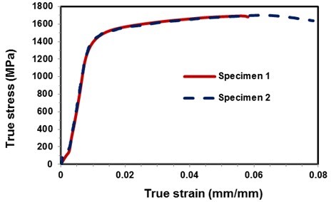
Fig. 4. The stress strain relationship for 75Cr1 steel
From the elastic part of the experiment, the modulus of elasticity was determined, which amounted to 190,000 MPa. The values of yield strength and tensile strength are in very good agreement with the values reported by Heisel et al. (2015), while the values differ significantly from those reported by Wang et al. (2016). The values shown in Fig. 4 were also used in the finite element simulation of rolling a circular sawblade.
The results of the experimental modal analysis of the sawblade in stationary and rotating states are shown in Fig. 5. The spectrum of natural frequencies of the stationary sawblade is shown in red, while the spectrum of natural frequencies when the sawblade is rotated by 3 Hz is shown by the black curve. The frequencies of the backward and forward travelling waves are visible from the spectrum; these were excited by short pulses, and the corresponding mode shape was determined using Eq. 1.
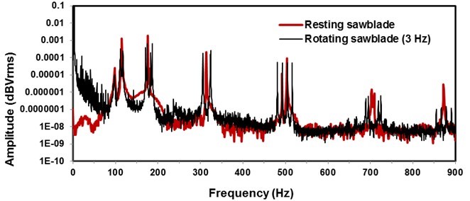
Fig. 5. Spectrum of natural frequencies of the tested sawblade: red – stationary sawblade; black – rotating sawblade with a rotational speed of 3 Hz
The measurement of the cross-sectional profile of rolling on the top and bottom of the sawblade along with the curve of the average value is shown in Fig. 6.
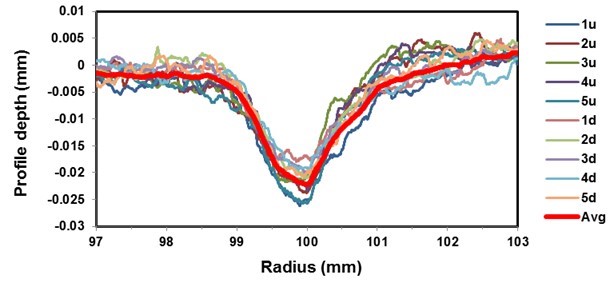
Fig. 6. Measured rolling profile of the tested sawblade
The figure shows a uniform rolling profile at different positions. The profiles on the upper side are slightly different from those on the underside on the outer part of the rolling area, while the profiles on the area of rolling and on the inside part of the rolling are the same. The figure shows a higher level of material on the outside part of the rolling area than on the inside part of the rolling area. The reason could be the thrusting of the material on the outside part of the rolling field, as the roller does not roll in a straight line in relation to the sawblade, but also rotates in a circle around the vertical axis. As will be seen later, the rolling simulation with the finite element method did not show material thrusting. The reason might be that a greater coefficient of friction between the roller and the sawblade was used than in the simulation.
Figure 7 shows cross-sections of rolling profiles calculated with FEM for various sizes of forces, together with the measured profile. The figure clearly shows good agreement between the measured and the calculated profiles using a rolling force of 7800 N. It can be concluded that the sawblade is rolled with a force of approximately 7800 N and a roller with a crown diameter of 25 mm.
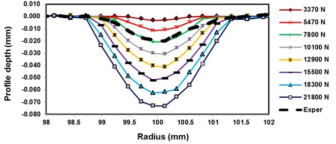
Fig. 7. Calculated and measured rolling profiles
Figures 8 and 9 show the distribution of radial and tangential stresses of the sawblade rolled with a force of 7800 N at rest and at a rotational speed of 100 Hz. The red line in Fig. 8a shows the position of the stresses, which are shown in Fig. 9.
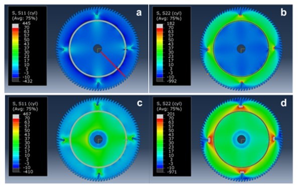
Fig. 8. Radial and tangential stress distribution of a roll-tensioned sawblade: a) radial stress, 0 Hz rotational speed; b) tangential stress, 0 Hz rotational speed; c) radial stress, 100 Hz rotational speed; d) tangential stress, 100 Hz rotational speed
In the case of the stationary sawblade, the distribution of radial stresses is compressive in the inner and outer part of the rolling area, whereas the distribution of the tangential stress in the inner part is partially tensile and partially compressive. In the outer part, the distribution is highly tensile and ranged from 27 MPa in the vicinity of the rolling area to 17 MPa at the periphery of the sawblade. The impact of the rotation can also be seen from the images, as the stresses become purely tensile and increase noticeably in the inner and outer parts of the sawblade, both in radial and tangential directions, where the latter increases in the outer part from 27 to 44 MPa near the rolling area and on the periphery from 17 to 26 MPa. Similar stress distribution for the same rolling force was found also by Heisel et al. (2015).
Figure 9 also shows an increase in stress caused by the rotation of the blade in the clamping area, where the sawblade was clamped with a flange having a diameter of 75 mm. If the sawblade in the simulation were rigidly clamped in the same area, the increase in stress would not be possible.
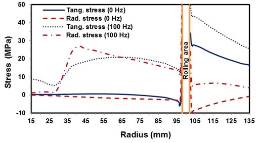
Fig. 9. Radial and tangential stress distribution for a roll-tensioned sawblade at rotational speeds of 0 and 100 Hz. The location of stresses is indicated by the red line in Fig. 8a.
The detailed distribution of radial and tangential stresses caused by the rolling of a stationary sawblade along with the corresponding mesh is shown in Fig. 10. From the figure, it can be seen that the radial stress fluctuates from 120 MPa in compression to 110 MPa in tension, whereas the tangential stress ranges from 550 MPa in compression to 50 MPa in tension.
Figure 11 presents the calculated natural frequencies of the sawblade as a function of the rolling force. The figure indicates that the natural frequencies increase with the rolling force in all the modes except at the modes with nodal diameters of 0 and 1, where the natural frequencies are decreasing.
The calculated critical speed of the sawblade as a function of the rolling force is presented in Fig. 12, where it can be seen that the critical speed of the sawblade increases with the rolling force. The lowest critical speed has the mode with three nodal diameters. The figure does not show the critical speed for zero and the first nodal diameter, as the mode with zero nodal diameter does not have a forward and backward travelling wave; for the first nodal diameter mode, the frequency of the backward travelling wave never reaches zero, as the rotational stiffness K for that mode is too high. Similar values were measured by Stakhiev (1999).
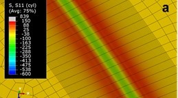

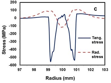
Fig. 10. Stress distribution in the rolling area: a) radial stress; b) tangential stress; c) comparison of stresses
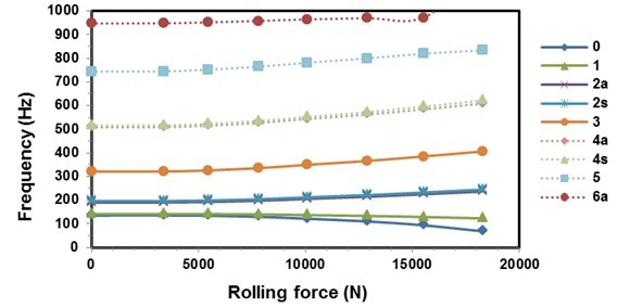
Fig. 11. Calculated natural frequencies as a function of rolling force. s – Symmetrical mode, and a – Asymmetrical mode
The same figure also shows the theoretical lateral stiffness of the sawblade, where the initial stiffness of 61 N/mm first decreases when increasing the rolling force and then increases to the maximum value of 86 N/mm at a rolling force of 7800 N. After that, the stiffness again decreases when increasing rolling forces down to 37 N/mm at a rolling force of 18,300 N, where partial dishing occurs, and further to 21 N/mm at a rolling force of 21,800 N, where total dishing occurs at the smallest lateral force (Fig. 13). Comparing the calculated values with the recommendations of Stakhiev (2000), who recommends that the minimum lateral stiffness for rip-sawing and cross-sawing should be 40 N/mm and 25 N/mm, respectively, it can be concluded from the above analysis that Stakhiev’s recommended values are too small.
The experimentally determined lateral stiffness of the sawblade on the periphery was 61 N/mm, which is lower than the theoretical stiffness, which was calculated to be 86 N/mm. As we will see later, the experimental natural frequencies are also slightly lower than those calculated theoretically. The reason could be the lower stiffness of the experimental sawblade clamping or increased modelled stiffness as the flanges were modelled as centrally rigidly clamped, but in reality the flanges are fixed to the shaft. Another reason could be a material property. From the tensile test the mechanical properties were measured only in one direction, while Heisel et al. (2015) indicate slightly different mechanical properties in different directions.
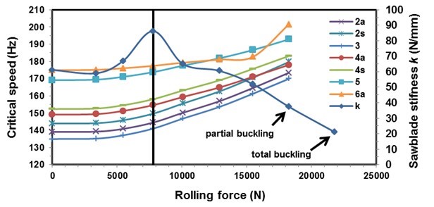
Fig. 12. Calculated critical speed as a function of rolling force. s – Symmetrical mode, and a – Asymmetrical mode
The vertical line in Fig. 12 indicates the force of 7800 N, with which the experimental sawblade has been rolled. Because at the aforementioned rolling force, the theoretical lateral stiffness of the sawblade is a maximum, it could be said that the tested sawblade has been rolled with the goal of maximising the lateral stiffness. By increasing the rolling force, the sawblade would have achieved a greater theoretical critical speed, but its lateral stiffness would greatly decrease.
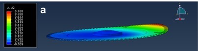
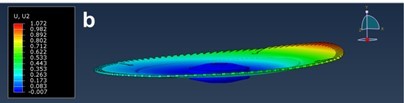
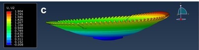
Fig. 13. Circular saw deflection at a lateral force of 40 N and different rolling forces: a) rolling force of 15,500 N; b) rolling force of 18,300 N; c) rolling force of 21,800 N
From the experimentally determined natural frequencies of the sawblade and using the calculated rotational stiffness K, the actual critical speed of the sawblade was calculated as shown in Table 1, where the theoretical natural frequencies for modes with 0 to six nodal diameters and their theoretical critical speed are also presented. The ratios between the experimental and theoretical natural frequencies are also shown in the table. The values reveal that the measured frequencies are slightly lower than the theoretical ones and differ from 7% to 13% for mode shapes with two to four nodal diameters, which is the same for the ratios of theoretically and experimentally determined critical speeds. Given that for the determination of the critical speed, the mode shape with three nodal diameters is usually the most important (Stakhiev 1999), and that in our case, the rolling force was determined on the basis of the depth of the rolling profile and taking into account the previously mentioned reasons for the difference between the measured values and the theoretically calculated ones, it can be argued that the calculated values are in very good agreement with the experimental ones.
Table 1. Measured (νm,nexp) and Calculated (νm,nFEM) Natural Frequencies, Rotational Stiffness Coefficient (K), and Critical Speeds (νcrit) for Modes with Different Nodal Diameters (n)
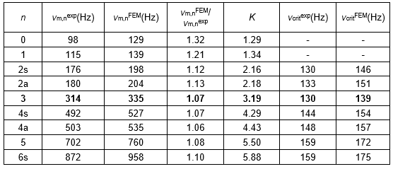
The actual critical speed for the sawblade is 130 Hz or 7800 rpm, and the theoretically calculated speed is 139 Hz or 8340 rpm. Per the recommendations of Stakhiev (1998), the maximum rotational speed of the sawblade should not exceed 85% of the minimum critical speed. The rotational speed of our experimental sawblade, which was clamped with flanges and had a diameter of 75 mm, amounted to 6630 rpm. According to the analysis conducted, the sawblade could be rolled with a slightly higher force, which would increase the natural frequencies and consequently the critical speed, but at the same time it would rapidly decrease the lateral stiffness. On the other hand, it is necessary to take into account the fact that the recommended flange diameter is 1/3 of the sawblade diameter, which in our case would be 100 mm. If the sawblade with the 100 mm flanges were tested, the natural frequencies and thus the critical speed would increase. As mentioned at the beginning of this article, the analysis was made with a flange of 75 mm in diameter. The reason for that is that most woodworking circular sawing machines on which sawblades that are 200 to 350 mm in diameter and can be clamped have flanges 75 mm in diameter.
CONCLUSIONS
- This work confirmed the method of measurements and calculations of critical speed for a commercial sawblade, available on the market, where no data about the sawblade are known, especially the effect of roll-tensioning, as the actual values of the natural frequencies of the relevant vibration modes differ from the calculated ones only by 7%, where the calculated values are higher than those experimentally determined. In the case there would be higher discrepancies between the measured and calculated values, deeper analysis would be needed and more sawblades should be tested.
- The analysis conducted on a commercially available circular sawblade showed that the maximum rotational speed amounted to 6630 rpm. In the test, the clamping ratio was 0.25, but if the sawblade was clamped with the recommended ration of 1/3, then the natural frequencies would be higher and consequently the critical speed would be higher as well.
- The conducted experiment indicates the real problem in practice, as universal circular sawing machines usually have a flange diameter of approximately 75 mm, with which smaller sawblades can also be clamped. The problem arises when clamping bigger sawblades, as in these cases, the clamping ratio is less than the recommended 1/3; consequently, the critical speed of the sawblade is also lower.
- The analysis also showed that the sawblade is rolled with the force at which the lateral stiffness on the sawblade periphery has the maximum value. From the perspective of the critical speed, the sawblade could be rolled with a higher force, which would further increase the critical speed, but the lateral stiffness of the sawblade would begin to decrease rapidly.
ACKNOWLEDGMENTS
The authors acknowledge the support of the Slovenian Research Agency within the framework of programs P2-0182, P2-0248, and P4-0015 .
REFERENCES CITED
Beljo-Lucic, R., and Goglia, V. (2001). “Some possibilities for reducing circular saw idling noise,” Journal of Wood Science 47(5), 389-393. DOI: 10.1007/BF00766791
Cristovao, L., Ekevad, M., and Gronlund, A. (2012). “Natural frequencies of roll-tensioned circular sawblades: Effects of roller loads, number of grooves, and groove positions,” Bioresources 7(2), 2209-2219. DOI: 10.15376/biores.7.2.2209-2219
Droba, A., Javorek, L., Svoreň, J., and Paulíny, D. (2015). “New design of circular saw blade body and its influence on critical rotational speed,” Drewno 58(194), 147-157. DOI: 10.12841/wood.1644-3985.081.12
Ellis, R. W., and Mote, C. D. (1978) “Increased lateral saw stiffness and vibration damping with feedback control,” Wood Science 11(1), 56-64.
Heisel, U., Stehle, T., and Ghassemi, H. (2015). “Experimental investigation into parameters influencing roll tensioning of circular saw blades,” Journal of Machine Engineering 15(1), 98-111.
Holøyen, S. (1987). “Vibrations and natural frequencies of angular slot circular saws,” Holz als Roh- und Werkstoff 45(3), 101-104. DOI: 10.1007/BF02605981
Hutton, S. G. (1991). “The dynamics of circular saw blades,” Holz als Roh- und Werkstoff 49(3), 105-110. DOI: 10.1007/BF02614349
Ishihara, M., Noda, N., and Ootao, Y. (2010). “Analysis of dynamic characteristics of rotating circular saw subjected to thermal loading and tensioning,” Journal of Thermal Stresses 33(5), 501-517. DOI: 10.1080/01495731003659208
ISO 6892-1 (2016). “Metallic materials — Tensile testing — Part 1: Method of test at room temperature,” International Organization for Standardization, Geneva, Switzerland.
Kaczmarek, A., Orłowski, K., and Javorek, L. (2016a). “The effect of circular saw blade clamping diameter on its resonant frequencies,” Applied Mechanics and Materials 838, 18-28. DOI: 10.4028/www.scientific.net/AMM.838.18
Kaczmarek, A., Orlowski, K. A., and Javorek, L. (2016b). “A brief review and comparison of selected experimental methods for measuring natural frequencies of circular saw blades,” Drewno 59(197), 231-239. DOI: 10.12841/wood.1644-3985.C09.11
Li, B., Zhang, Z., Li, W., and Peng, X. (2015a). “Effect of yield strength of a circular saw blade on the multi-spot pressure tensioning process,” BioResources 10(4), 7501-7510. DOI: 10.15376/biores.10.4.7501-7510
Li, B., Zhang, Z., Li, W., and Peng, X. (2015b). “A numerical simulation on multi-spot pressure tensioning process of circular saw blade,” Journal of Wood Science 61(6), 578-585. DOI: 10.1007/s10086-015-1508-5
Li, S., Wang, C., Zheng, L., Wang, Y., Xu, X., and Ding, F. (2016). “Dynamic stability of cemented carbide circular saw blades for woodcutting,” Journal of Materials Processing Technology 238, 108-123. DOI: 10.1016/j.jmatprotec.2016.07.018
Leu, M. C., and Mote, C. D. (1984). “Origin of idling noise in circular saws and its suppression,” Wood Science and Technology 18(1), 33-49.
Mote, C. D., and Nieh, L. T. (1973). “On the foundation of circular saw stability theory,” Wood and Fiber 5(2), 160-169.
Mote, C. D., and Szymani, R. (1977). “Principal developments in thin circular-saw vibration and control research. I. Vibration of circular saws,” Holz als Roh- und Werkstoff 35(5), 189-196. DOI: 10.1007/BF02610942
Orlowski, K., Sandak, J., and Tanaka, C. (2007). “The critical rotational speed of circular saw: simple measurement method and its practical implementations,” Journal of Wood Science 53(5), 388-393. DOI: 10.1007/s10086-006-0873-5
Parker, R. G., and Mote, C. D. (1989). “Asymmetric tensioning of circular saws,” Holz als Roh- und Werkstoff 47(4), 143-151. DOI: 10.1007/BF02614477
Radcliffe, C. J., and Mote, C.D. (1981). “Active control of circular saw vibration using spectral analysis,” Wood Science 13(3), 129-139.
Schajer, G. S., and Mote, C. D. (1983). “Analysis of roll tensioning and its influence on circular saw stability,” Wood Science and Technology 17(4), 287-302.
Schajer, G. S., and Mote, C. D. (1984). “Analysis of optimal roll tensioning for circular saw stability,” Wood and Fiber Science 16(3), 323-338.
Schajer, G. S. (1986). “Why are guided circular saws more stable than unguided saws?” Holz als Roh- und Werkstoff 44(12), 465-469. DOI: 10.1007/BF02608068
Skoblar, A., Andjelic, N., and Zigulic, R. (2016). “Determination of critical rotational speed of circular saws from natural frequencies of annular plate with analogous dimensions,” International Journal for Quality Research 10(1), 177-192. DOI: 10.18421/IJQR10.01-09
Stakhiev, Y. (1998). “Research on circular saws vibration in Russia: From theory and experiment to the needs of industry,” Holz als Roh-und Werkstoff 56(2), 131-137. DOI: 10.1007/s001070050284
Stakhiev, Y. (1999). “Research on circular saws roll tensioning in Russia: Practical adjustment methods,” Holz als Roh-und Werkstoff 57(1), 57-62. DOI: 10.1007/PL00002622
Stakhiev, Y. (2000). “Today and tomorrow circular sawblades: Russian version,” Holz als Roh-und Werkstoff 58(4), 229-240. DOI: 10.1007/s001070050417
Stakhiev, Y. (2003). “Research on circular saw disc problems: Several of results,” Holz als Roh-und Werkstoff 61(1), 13-22. DOI: 10.1007/s00107-002-0353-6
Stakhiev, Y. (2004). “Coordination of saw blade tensioning with rotation speed: Myth or reality?” Holz als Roh-und Werkstoff 62(4), 313-315. DOI: 10.1007/s00107-004-0490-1
Szymani, R., and Mote, C. D. (1974). “A review of residual stresses and tensioning in circular saws,” Wood Science and Technology 8(2), 148-161.
Szymani, R., and Mote, C. D. (1977). “Principal developments in thin circular saw vibration and control research. II. Reduction and control of saw vibration,” Holz als Roh- und Werkstoff 35(6), 219-225. DOI: 10.1007/BF02608337
Vesely, P., Kopecky, Z., Hejmal, Z., and Pokorny, P. (2012). ”Diagnostics of circular sawblade vibration by displacement sensors,” Drvna Industrija 63(2), 81-86. DOI: 10.5552/drind.2012.1130
Wasielewski, R., Orlowski, K. A., and Szyszkowski, S. (2012). “Economical wood sawing with circular saw blades of a new design,” Drvna Industrija 63(1), 27-32. DOI: 10.5552/drind.2012.1121
Yu, R. C., and Mote, C. D. (1987). “Vibration of circular saws containing slots,” Holz als Roh- und Werkstoff 45(4), 155-160. DOI: 10.1007/BF02627571
Yuan, L. (2012). “Influence of radial slots on the vibration characteristics of circular saw blade,” Applied Mechanics and Materials 226, 232-236. DOI: 10.4028/www.scientific.net/AMM.226-228.232
Zhang, M., Zhang, Y., Ke, J., Li, X., and Cheng, L. (2014). “The influence of tangential roller pressure on the stability of circular saw blade,” Applied Mechanics and Material 614, 32-35. DOI: 10.4028/www.scientific.net/AMM.614.32
Article submitted: March 8, 2017; Peer review completed: May 26, 2017; Revised version received and accepted: June 9, 2017; Published: June 19, 2017.
DOI: 10.15376/biores.12.3.5569-5582