
Abstract
Load limit capacity, stiffness, and failure mechanisms were evaluated for the bending of two new types of furniture joints: one with an adhesive-bonded flat cross fastener, and the other with a frictional eccentric fastener. The results were compared with a commonly known direct thread connection used as a reference. For each of the three investigated types of joints, their strength-displacement curves and failure mechanisms were compared. The obtained results confirmed that the two new fasteners are suitable for making furniture joints with more advantageous load capacity and stiffness, as compared with the thread connection.
Download PDF
Full Article
Experimental Analysis of New Furniture Joints
Bogdan Branowski,a Marek Zabłocki,a and Maciej Sydor b,*
Load limit capacity, stiffness, and failure mechanisms were evaluated for the bending of two new types of furniture joints: one with an adhesive-bonded flat cross fastener, and the other with a frictional eccentric fastener. The results were compared with a commonly known direct thread connection used as a reference. For each of the three investigated types of joints, their strength-displacement curves and failure mechanisms were compared. The obtained results confirmed that the two new fasteners are suitable for making furniture joints with more advantageous load capacity and stiffness, as compared with the thread connection.
Keywords: Joint; Fastener; Load-carrying ability; Stiffness; Strength design of furniture
Contact information: a: Poznan University of Technology, Faculty of Machines and Transportation, Piotrowo 3, 60-101 Poznań, Poland; b: Poznań University of Life Sciences, Faculty of Wood Technology, Wojska Polskiego 28, 60-637 Poznań, Poland; *Corresponding author: sydor@up.poznan.pl
INTRODUCTION
In many cases, only experimental structural tests can provide a reliable determination of the influence of geometric dimensions and physical properties of interacting components on specific performance of a new product (Dietrich 1985). This paper presents tests results for two types of new furniture fasteners used to attach furniture legs to the seat or table tops. For both fasteners, patent applications have been submitted (Branowski et al. 2017a; Branowski et al. 2017b).
In view of a lack of reports in available literature presenting testing results for fasteners of a comparable design, this paper refers only to the testing results of two new fasteners compared with the conventional tapered thread fasteners, which are considered as the reference fastener. The experimental analysis presented in this paper was performed with two objectives: (i) to specify in detail the form and arrangement of component parts of the designed fasteners and collect the values of its structural features that are difficult or impossible to be determined under a different procedure, and (ii) to verify the structural properties of the limit load state of joints by comparing new joints with similar tests completed for a reference joint common in the industry. The tests were performed on samples of two new fasteners: an adhesive-bonded flat cross fastener (Branowski et al. 2017a) and a frictional eccentric fastener (Branowski et al. 2017b). The obtained results were compared with analogous test results for a commonly known tight-fit taper thread connection. Difficulties in mathematical modelling of the actual limit load capacity and stiffness of semi-rigid connections made of wood materials prevent the effective strength design of furniture (Branowski and Pohl 2004). The determination of static force-displacement paths in the function of load for newly-designed joints (and later a comparison with their analogous paths for known structural nodes) makes it possible to reduce the risk of designing a piece of furniture that provides insufficient load capacity. The joints investigated in this paper are classified as semi-rigid connections. The load is applied by initial tension during assembly and operational loads. Both types of loads are impossible to determine precisely, due to unknown values of the forces exerted by assembly, depending on the manufacturing technology of joined sub-assemblies (precision of production, variable strength properties of wood materials – (Sydor and Wieloch 2009)), as well as the adopted assembly conditions and method. The value of the operational loads to be applied depend on incompletely known factors: operation mode, ambient conditions (temperature and humidity), and the method of furniture storage and transport (Eckelman et al. 1988; Eckelman 1999; Çolakoğlu and Apay 2012; Hajdarević and Busuladžić 2015; Smardzewski 2015).
This paper presents only the results of comparative studies performed after the determination of detailed structural forms and dimensions of joints made with the fasteners in question.
EXPERIMENTAL
Design of the Tested Joints
The first furniture joint connected a leg with the seat and was made using an adhesive-bonded flat cross fastener. The fastener was disclosed in the patent application (Branowski et al. 2017a), as shown in Fig. 1. For strength tests, legs made from beech wood (part no. 4) with a square section of 38 × 38 mm and a length of 410 mm were used. The tight-fit plates of the cross fastener (parts no. 2 and no. 3) were made from 8-layered beech plywood with a thickness of 4 mm. Crosswise grooves were cut in the plates to facilitate adhesive bonding. The 26 mm thick seat (part. no. 1) was made from two bonded medium-density fibreboard (MDF) with a thickness of 16 mm and 10 mm.
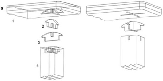
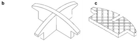
Fig. 1. A leg-seat joint made with an adhesive-bonded flat cross fastener (a): 1 – seat; 2 & 3 – cross plates; 4 – leg; b) flat cross fastener; c) adhesive grooves on the surface of one of the plates (source: (Branowski et al. 2017a))
Another new joint (Fig. 2) made with a frictional eccentric fastener solves the problem that prevents the disassembly of legs in a stool, chair, or table, as disclosed in the patent application (Branowski et al. 2017b). Friction forces determining the eccentric joint are obtained by the wedge effect on pressed cylindrical surfaces of the contact with an increased friction coefficient due to the applied abrasive material layer.
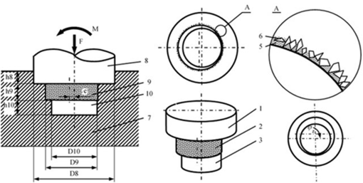
Fig. 2. A leg-seat joint using a pre-tensioned friction type eccentric fastener and with top-surface abrasive layer: 1 – upper concentric pin of the leg; 2 – middle eccentric pin of the leg; 3 – lower concentric pin of the leg; 5 – adhesive material; 6 – abradant; 7 – seat board; 8 – interaction of pin #1 with concentric socket; 9 – interaction of pin #2 with eccentric socket; 10 – interaction of pin #3 with concentric socket (source: (Branowski et al. 2017b)); jz – wedge angle.
Figure 2 shows the eccentric fastener of the leg. It consisted of three pins (#1, #2, #3). Pins #1 and #3 are cylindrical and concentric, while #2 is also cylindrical, but eccentric relative to the axis of pins #1 and #3. On the surface of the eccentric pin, an adhesive abrasive layer 4 was applied. The abrasive material 5, in the form of powder with a specified particle size grade, was applied on the surface of the leg eccentric pin, already with an adhesive layer applied with a brush 6 (adhesive or varnish). Then, another adhesive layer was applied after the first layer had dried 6. Corundum adhesive grains bonded to the leg surface were pressed into both eccentric socket-eccentric pin contact surfaces when the leg was rotated during assembly. In addition, Figure 2 shows the joint of leg 1 and a socket in board 7 (of a chair seat or table top). The two openings in sockets 8 and 10 were concentrically cylindrical, whereas the third opening, 9, was eccentric. The eccentric pins, e, in the leg and the socket had the same parameters. The angle of rotation during leg assembly consisted of a dead angle of rotation (to overcome the play in leg pins) and the angle of the working clamp (when pressing the leg to the eccentric socket). The direction of the working load exerted by the bending moment relative to the eccentric pin in the socket, clearance L, of the eccentric pin, e, i, and the precision of the pin and fastener socket production determined whether self-locking was maintained. Self-locking is usually provided by satisfying the condition e/D9 ≤ 0.05, which is similar to standardised eccentric clamps. Then, when rotating the leg in the opening during assembly, the wedge angle jz – Fig. 2 – kept changing (from 0 to jz max); the angle was formed between tangential lines to the radii of the eccentric socket and the cylindrical socket of the leg pins. The condition of the angle jz > 0 had to be met to obtain fastening.
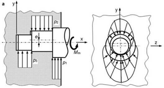
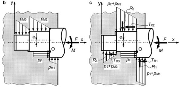
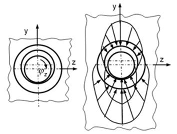
Fig. 3. Changes in the distribution of pressing forces in the frictional eccentric fastener: a – at initial pressing force during assembly; b – at working load on the leg by axial force F and bending moment M; c – total pressing forces (source: (Branowski et al. 2017b))
Key: p1-p3 – assembly pressing forces on pins 1, 2 and 3; pM1-pM3 – working pressing forces on pins 1, 2, and 3 by bending moment M while rotating the leg around the momentary rotation point O; pF – working pressing forces on the face surface exerted by axial force F
The created peripheral scratches and pressing forces during leg assembly interacted with the pressing forces applied by utility load (axial force and bending moment). The assembly pressing forces of the eccentric pins were balanced by the reaction pressing forces of leg cylindrical parts. Great frictional forces in the friction-tight fit contact of the leg-abrasive material-socket provided self-locking of the joint. The potential loss of self-locking required that abrasive grains should cut new longitudinal grooves.
Figure 3 shows changes of the distribution of pressing forces: at the initial clamping during assembly (Fig. 3a), at the working load of the leg by axial force F and bending moment M (Fig. 3b), and the total pressing forces (Fig. 3c).
The occurrence of pressing forces in a given direction of the bending moment was the condition for joint self-locking. The distribution of pressing forces (Fig. 3a) in the radial direction was parabolic, which resulted in the fact that some directions of the later-applied working load to the leg by the bending moment were privileged. In the centre of gravity, concentrated normal forces R1, R2, and R3 were applied to the contact place. Their values were crucial for joint self-locking.
The removal of the leg from the socket was counteracted by friction force T = TR1+TR2+TR3 = R1m1+R2m2+R3m3, where T = friction forces and R = normal force. An increased friction coefficient m2 at the contact by the abrasive material improved the transfer of load by friction forces TR2 = m2 R2.
A direct taper-thread connection of the leg and the board is shown in Fig. 4. This joint had similar geometric dimensions to the two already described joints (Fig. 1 and Fig. 3) (diameter d = 30 mm; pitch h = 4 mm; pitch angle a = 90°, rate of taper 1:5).
The thread connection was self-locking and resistant to changes of ambient humidity and temperature. The resistance was obtained by the adjustment of pre-tension. Other permanent rheological deformations under operational loads could be compensated by additional initial tension.
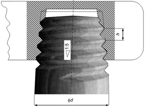
Fig. 4. Leg-seat joint using taper thread
Qualitative Criteria for the Tested Joints
Qualitative criteria of the leg-board joint were assumed as quantities characteristic in bending tests: limit load capacity, i.e. the maximum transverse bending force Fmax on the given arm l and conventional stiffness k of the semi-rigid connection on the graph presenting the relationship of force F and strain s of the leg (Fig. 5). The F(s) graph also characterized the dependence of bending moment M from the internal angle of leg rotation q in the joint, as elastic bending deformations of the leg itself had no relevant impact on the results. Thus, the path of the static curve F(s), or M(q), of the joint (M=F∙l; q = arctg s/l at l @ const) was studied, wherein the path determines the limit load capacity relative to bending Fmax, possibility of rotation sFmax of the joint and identifies the behaviour of component parts of joint nodes in the critical stress state (failure mechanisms). On the graph of F(s), there is the angle ω characterising conventional stiffness of the joint k = tg ω = Fmax/sFmax.
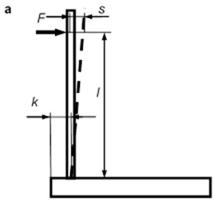
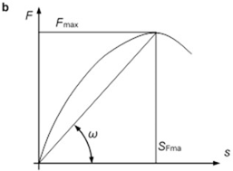
Fig. 5. Measured values of force F and leg strains s: a – diagram; b – F(s) graph
The joint strength test was performed at a laboratory owned by a well-known furniture company, using a specialized strength testing machine used to test load capacity of fasteners in various types of furniture joints. Figure 6 shows the test station at which the joint sample was installed. The force was exerted by the driving screw of the actuator, wherein actuator displacement was being recorded at the same time. The actuator rate of feed was 0.7 mm/s.
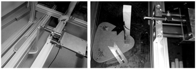
Fig. 6. The test station with two rigid sample installations
Sample of the Joint with an Adhesive-Bonded Flat Cross Fastener
The cross-fastener plates were made from 8-layer beech plywood with a thickness of 4 mm (by laser cutting). It was possible to obtain reproducible samples with a relatively high accuracy of ± 0.1 mm, with characteristic burning traces on the surface. On lateral surfaces of the cross fastener, crosswise adhesive groves were cut at a depth of approximately 0.4 mm, spaced at 3 mm. The radius of the curvature of the sample (Fig. 1) was selected in accordance with diameter sizes of cutters in the manual milling cutters used to make the grooves. Two perpendicular pass-through grooves were cut with a width ensuring a clearance of 0.2 mm between the board and the leg. To obtain proper strength of the bond, the depth of the milling cutter was selected accordingly to ensure uniform strength of the bond in the leg and the board. Thus, the perpendicular lateral surfaces of the locking grooves made in the board corresponded to the groove surfaces in the leg. For adhesive bonding, Technicoll CIA AID expanding polyurethane adhesive was used. Once prepared, the samples were seasoned under an initial load for 12 h.
Sample of the Joint with the Frictional Eccentric Fastener
To obtain the top surface of the leg eccentric pins with an abrasive layer, several methods were used to bond corundum grains and wood (Fig. 7), namely double-sided adhesive tape and an adhesive layer spread onto the wood surface. Appropriate bonding of the layered grains and wood was provided by double coating of waterproof polyurethane adhesive for wood applications, supplied by Technicqll (class D4). The corundum grains were deposited on the initially-applied adhesive layer. When the adhesive bonded, another external adhesive layer was applied, similarly to the abrasive paper or fabric manufacturing technology. For test purposes, three types of DHEK corundum grains were used with the size grade P36, 60, and 100. The DHEK P60 grain layer on the sample joint was the most appropriate due to layer thickness.
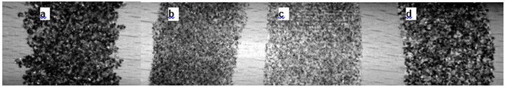
Fig. 7. Example joints with corundum grains: a – adhesive-bonded P60 corundum, b – adhesive-bonded P100 corundum, c – P100 corundum with double-side tape, d – P60 corundum with double-side tape
Samples of the Direct Thread Connection
To compare strength and stiffness of joints consisting of the two new fasteners with the direct thread connections known in the industrial practice, sample legs and seat boards supplied by a well-known furniture manufacturer were used. Geometric dimensions of the taper thread were as follows: maximum diameter d = 30 mm, pitch of thread h = 4 mm, thread angle a = 90°, and angle of cone generator inclination f = 6°. The legs were made from beech wood, and the seats consisted of two adhesive-bonded fibreboards with a total thickness of gp = 26 mm.
RESULTS AND DISCUSSION
Force-Displacement Curves
The test results were not statistically processed (number of samples, measurement errors, etc.). The described joint testing was carried out with three samples of each joint, wherein test results provided as test results with mean values were found reliable. Accuracy of the measurements taken with a specialised strength testing machine was as follows: within the force range ±0.1 N and within the displacement range ±0.1 mm. The measurement results relating to force and displacement were recorded by a computer. Data files relating to force and the angle of rotation of the machine’s driving screw were processed using a spreadsheet program and the displacement referred to the force application point. The results were used as the basis to plot F(s) graphs for the tested joint samples.
Figures 8 through 10 show the obtained strength curves of the tested furniture joints. The results made it possible to perform a comparative analysis of their quality (regarding force-displacement curves). While analysing the results for the investigated model (in fact, a span beam), emphasis must be put on elastic deflection of the beech leg of fs = 1.38 mm (at F = 200 N, the length of loaded sample lp = 360 mm, diameter d = 30 mm, and Young’s modulus E = 16,000 MPa), and this has a negligible impact on the endpoint displacement f @ 27.1 mm. The deflection of the tested joint was almost completely caused by the rotation of the semi-rigid connection of the loaded leg (fs/f) × 100% = 5.2%.
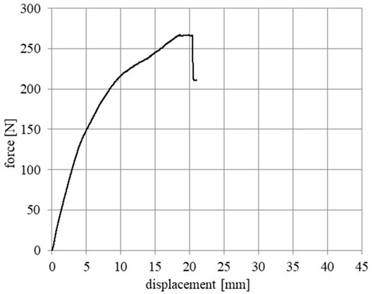
Fig. 8. Force-displacement curve for the joint with the adhesive-bonded flat cross fastener
Particularly advantageous structural features in terms of strength and stiffness were demonstrated by the joint with a flat cross fastener (Fig. 8). On the F(s) graph (Fig. 9a), when a given force value was exceeded, characteristic force slips occurred with an amplitude of approximately 5 N. The slips were accompanied by noises (scratching and knocking) that could be heard during load application. They could be equated with self-excited “stick-slip” vibrations during micro-pulling of the leg out of the opening in the table top. The abrasive layer clearly reduced force slips during load application; the created fit-friction node with the corundum grains being pressed into the surfaces of fastener elements limits displacement, which increased load capacity and stiffness of the joint (Fig. 9b). The taper thread joint (Fig. 10), widely used in industrial practice, features less advantageous force and stiffness parameters, regarding the joints with the two new fasteners being compared (Figs. 8 and 9).
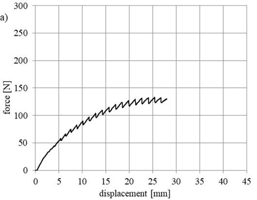
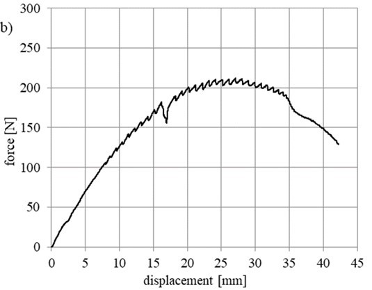
Fig. 9. Force-displacement curve of the joint with the frictional eccentric fastener: a – without the abrasive layer; b – with the abrasive layer
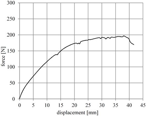
Fig. 10. Force-displacement curve of the joint with taper thread
Based on the data provided in Table 1, the most advantageous strength parameters regarding load capacity and stiffness characterize the joint with the adhesive-bonded flat cross fastener. The characteristics of the joints in Table 1 (sourced from Figs. 8 through 10) show that the joint with the eccentric fastener without any abrasive layer demonstrated a lower load capacity and stiffness, compared with the joint with the eccentric fastener with an abrasive layer. This result confirms the advantageous effect provided by the higher load capacity and stiffness after the top surface layer is modified with corundum grains.
Table 1. Summary of Main Characteristic Parameters of the Tested Joints
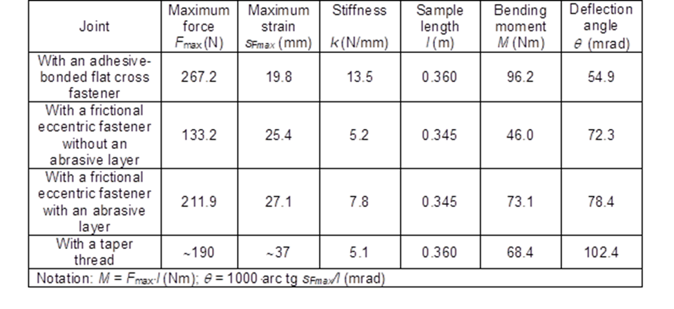
Moreover, the analysis concerned the advantages of the crosswise cuts on the surface of the lamella strips (joint with cuts and without cuts), the thickness of the adhesive layer (approximately 0.2 mm during the tests; for a thinner layer of 0.1 mm a much lower force Fmax was observed) on strength and stiffness of the joint with the cross fastener. The joints with eccentric fasteners showed an acceptable load capacity only when one section of the joint (one cylindrical turn of the leg joint) was covered with the abrasive material that created a fit-friction node limiting mutual displacement of the leg-table top joint (Fig. 9).
Failure Mechanisms
For the tested joints with cross fasteners two different failure mechanisms were observed (Fig. 11). For the first mechanism (Fig. 11a) the adhesive layer between the fastener and the leg experienced shearing, which resulted in a considerable reduction of the force on the graph (Fig. 8). The strength loss during further deformation resulted from the internal cracking of the fibre board (MDF), which was manifested by an audible crack. Outside the sample there were no visible signs of cracking or deformation of any part. A gap on the load application side was visible (created due to adhesive shearing). For the other mechanism (Fig. 11b) the strength loss was caused by delamination of the fibre board as well as the fastener being torn out of the fibre board (partially also due to adhesive shearing and the fastener sliding outside). There were no signs of the fastener being pulled out of the leg.
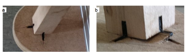
Fig. 11. Failure mechanisms of the joint with an adhesive-bonded flat cross fastener: a – shearing of the adhesive layer; b – MDF delamination and the cross fastener torn out of the board
The failure mechanism of the joint with the eccentric fastener with an abrasive layer was caused by local damage at the spots of maximum pressing forces on the surface. After the joint was dismantled, grooves cut by corundum grains were visible in the eccentric opening (Fig. 12a).
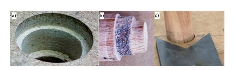
Fig. 12. Elements of the joint with the frictional eccentric fastener after the strength test:
a – visible grooves cut by corundum grains (MDF made by Kronopol Żary, Poland);
b – deformations of pins and damaged abrasive layer; c – clearance in the joint
The greatest deformations occurred on the pin with the smallest diameter (pin conicity as shown in Fig. 12b, right-hand side). Also distinct deformations for a larger diameter could be seen (Fig. 12b, left-hand side). Another failure mechanism was related to corundum grain losses on the intermediate eccentric pivot (Fig. 12b, in the middle of the figure). After the tests (when load was released), the joint showed distinct loosening, but its assembly (clamping) was still possible. Figure 12c shows the play created when the load was released from the investigated joint.
The direct thread connection of the leg and the seat failed due to board delamination (the wedge effect of the leg thread on the board thread). The crack started at the tread and continued to the edge of the board (Fig. 13).
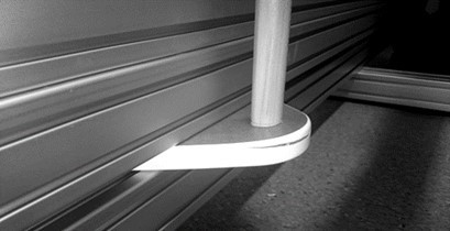
Fig. 13. Board delamination for the case of the taper thread connection
CONCLUSIONS
- The two new joints, submitted for patent protection, composed of adhesive-bonded flat cross fasteners and eccentric fasteners with abrasive layers, provided more advantageous load capacity and stiffness parameters, as compared to the direct thread connections commonly used in mass production (Table 1).
- Each of the three investigated types of joints experienced characteristic, yet different, failure mechanisms. For the joint with cross fasteners two different failure mechanisms were observed. One of the mechanisms consisted of adhesive failure; the other consisted of local failure of the joined fibreboard. For the joints with the eccentric fastener and tread connection local failure of the board occurred.
- It is possible to increase load capacity of joints: for the cross fastener joint – by increasing the adhesive bond strength, in other cases – by using fibreboards featuring more advantageous strength properties or using local board modifications (g. as presented in the publication (Sydor and Wołpiuk 2016). The obtained results may be useful in strength design of furniture. Failure mechanisms observed for the fasteners in this study are difficult to present in theoretical analytical models. This fully confirms high usefulness of experimental design testing of wood-based materials.
Testing results presented in this paper are preliminary in character. They show the course of the displacement-force dependence for the analysed statically loaded fasteners. Prior to the implementation of the new fasteners in commercial-scale production strength testing is needed taking into consideration high variability in properties of joined materials (including statistical analysis) and tests applying dynamic loads and fatigue strength.
REFERENCES CITED
Branowski, B., and Pohl, P. (Eds.). (2004). Modelowanie półsztywnych węzłów konstrukcyjnych mebli [Modeling of Semi-rigid Furniture Joints], Wydawnictwo Akademii Rolniczej im. Augusta Cieszkowskiego, Poznań, Poland.
Branowski, B., Zabłocki, M., Kurczewski, P., and Pohl, P. (2017a). “PL 421875 A1,” Meblowe połączenie nogi z blatem lub siedziskiem [Connection of furniture leg with table top or chair seat], Polish Patent Office, Warsaw, Poland.
Branowski, B., Zabłocki, M., Torzyński, D., and Pohl, P. (2017b). “PL 421874 A1,” Cierne złącze meblowe z dociskiem mimośrodowym [Frictional furniture joint with eccentric clamp], Polish Patent Office, Warsaw, Poland.
Çolakoğlu, M. H., and Apay, A. C. (2012). “Finite element analysis of wooden chair strength in free drop,” International Journal of Physical Sciences 7(7), 1105-1114.
Dietrich, M. (1985). System i konstrukcja [System and Design] (2nd ed.), Wydawnictwa Naukowo-Techniczne, Warsaw, Poland.
Eckelman, C. (1999). “Performance testing of side chairs,” European Journal of Wood and Wood Products 57(4), 227-234.
Eckelman, C. A., Hill, M., and Cassens, D. (1988). “Performance testing of furniture. Part II. A multipurpose universal structural performance test method,” Forest Product Journal 38(4), 13-18.
Hajdarević, S., and Busuladžić, I. (2015). “Stiffness analysis of wood chair frame,” Procedia Engineering 100, 746-755. DOI: 10.1016/j.proeng.2015.01.428
Smardzewski, J. (2015). Furniture Design, Springer, Dordrecht, Netherlands. DOI: 10.1007/978-3-319-19533-9.
Sydor, M., and Wieloch, G. (2009). “Construction properties of wood taken into consideration in engineering practice,” Drewno 52(181), 63-73.
Sydor, M., and Wołpiuk, M. (2016). “Analysis of resistance to axial withdrawal of screws embedded in locally reinforced MDF,” Drewno 59(196), 173-182. DOI: 10.12841/wood.1644-3985.093.14
Article submitted: August 31, 2017; Peer review completed: October 22, 2017; Revised version received and accepted: November 7, 2017; Published: November 20, 2017.
DOI: 10.15376/biores.13.1.370-382