
Abstract
To evaluate the static and seismic behaviour of glulam beam-to-column connections with screwed-in threaded rods, nine specimens grouped in three were tested under both monotonic and reversed cyclic loads. The failure modes, moment resistance, initial rotation stiffness, ductility, and energy dissipation capacity of the developed connections were investigated. The results indicated that the developed beam-to-column connections showed superior structural performance. Furthermore, with the introduction of a steel bracket, the hybrid screwed-in threaded rod connection features larger stiffness, higher load-carrying capacity, remarkable ductility, and better energy dissipation capacity. The main failure modes included the yielding of steel brackets, as well as the yielding or rupture of the threaded rods, which indicated a ductile behaviour. The connection specimens with steel columns showed larger stiffness than those with glulam columns, which is reasonable for the bigger compressive deformation of glulam columns.
Download PDF
Full Article
Experimental Static and Seismic Behaviour of Glulam Beam-to-Column Connection with Screwed-in Threaded Rod Joints
Huifeng Yang,a,* Chaochao Wang,a Junbin Hu,a Haotian Tao,b Jiwei Liu,b Liqiu Tang,a and Benkai Shi a
To evaluate the static and seismic behaviour of glulam beam-to-column connections with screwed-in threaded rods, nine specimens grouped in three were tested under both monotonic and reversed cyclic loads. The failure modes, moment resistance, initial rotation stiffness, ductility, and energy dissipation capacity of the developed connections were investigated. The results indicated that the developed beam-to-column connections showed superior structural performance. Furthermore, with the introduction of a steel bracket, the hybrid screwed-in threaded rod connection features larger stiffness, higher load-carrying capacity, remarkable ductility, and better energy dissipation capacity. The main failure modes included the yielding of steel brackets, as well as the yielding or rupture of the threaded rods, which indicated a ductile behaviour. The connection specimens with steel columns showed larger stiffness than those with glulam columns, which is reasonable for the bigger compressive deformation of glulam columns.
Keywords: Threaded rods; Screwed-in; Beam-to-column connection; Energy dissipater; Seismic behaviour
Contact information: a: College of Civil Engineering, Nanjing Tech University, Nanjing, 211816, China; b: School of Civil Engineering, Southeast University, Nanjing, 211189, China;
* Corresponding authors: hfyang@njtech.edu.cn; yhfbloon@163.com
GRAPHICAL ABSTRACT
INTRODUCTION
Joints and connections play extremely important roles in structural timber and steel design. For timber structures, the resistance, ductility, and energy dissipation depend on the connections (Xu et al. 2009; Leijten 2011; Liu and Yang 2019). With the increasing application of timber structures in multi-story and long-span structures, it is necessary to develop new types of jointing or connection systems to meet the needs of prefabrication, efficiency, high performance, etc.
The dowel-type connection is widely used in timber structures for its good economic performance, convenient assembly, and reliable force transmission (Liu and Yang 2019). However, traditional dowel-type connections show significant limitations on the connection load-carrying capacity and stiffness (Lam et al. 2010; Araki et al. 2011; Wang et al. 2015). As a result, it is usually considered as a hinge connection (Li et al. 2021), which deeply restricts the development of multi-story and long-span structures.
To obtain a ductile moment-resisting connection and meet the needs of high performance connection for timber structures, a large amount of research effort has been made. Typically, glued-in rod connections are introduced to timber structures. The primary attractive properties of this sort of connection include high load-carrying capacity, high stiffness, and aesthetic appearance (Yang et al. 2016). Buchanan and Fairweather (1993) investigated moment-resisting glulam beam-column connections with glued-in rods. Their results showed that the connection has a high level of moment resistance. Furthermore, while combined with some steel brackets, it can further overcome the environmental restrictions for glued-in rod connections, as the gluing process is conducted in an indoor environment. As another benefit from the introduction of the steel brackets, it allows a practical application and easy assembly (Yang et al. 2016).
A great deal of research work has been carried out on moment-resisting hybrid connections including finite element analysis (Vašek and Vyhnálek 2006), theoretical evaluation (Vašek and Vyhnálek 2006; Yang et al. 2016), and design process (Fragiacomo and Batchelar 2012a,b). Nevertheless, the gluing quality control is a potential problem, and the evaluation of durability behaviour of glued-in rod connections is still inadequate. Therefore, the application of glued-in rod connections in timber structures is restricted.
The screwed-in threaded rod joint is an axially loaded mechanically fastened joint, featuring large stiffness and high load-carrying capacity. With the development of screwed-in threaded rod joints and connections, the above existing problems for glued-in rod connections can be solved very well. Considerable research on the withdrawal behaviour of screwed-in threaded rod joints has been conducted. There have been experimental, numerical, and theoretical investigations of withdrawal capacity and stiffness of threaded rods screwed-in glulam timber (Stamatopoulos and Malo 2015; Stamatopoulos and Malo 2016; Stamatopoulos and Malo 2018; Stamatopoulos and Malo 2020; Yang et al. 2021). A model based on non-linear fracture mechanics has been used to estimate the withdrawal capacity of screws embedded in glulam (Jensen et al. 2012).
Some research has been undertaken on moment-resisting joints using screwed-in threaded rod. A moment-resisting joint system using screwed-in threaded rods (lagscrewbolt) shows high performance (Nakatani et al. 2006). Experimental, analytical, and numerical method were used to gauge the performance of a semirigid timber frame with screwed-in threaded rods (Mori et al. 2015). Both the analytical and numerical model showed good agreement with the experimental results. Based on previous studies, a hybrid moment-resisting joint system that combined screwed-in threaded rods and slotted bolted connection was presented (Komatsu et al. 2018). The developed hybrid joint features high initial stiffness, good yielding capacity, and considerable ductility.
In this work, a hybrid connection consisting of screwed-in threaded rod and steel brackets was developed. A series of monotonic and reversed cycle loading tests were implemented to evaluate the static and seismic performance. In addition, the failure modes, load-carrying capacity, initial stiffness, ductility, and energy dissipation capacity of the connections were evaluated.
EXPERIMENTAL
Materials
The physical and mechanical properties of the glulam elements are shown in Table 1. The characteristic yield strength of the threaded rods is 800 MPa. The outer and root thread diameter of the rods are 20 mm and 15 mm, respectively. The steel bracket, which is designed to connect beam to column elements in some specimens, was fabricated using grade of Q235 with the yield strength of 235 MPa (GB/T 50017 2017). The strength grade of anchoring bolts are 8.8 with the yield strength of 640 MPa.

Sample Preparation
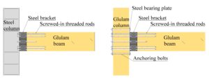
As shown in Figs. 1(a), 1(b), and 1(c), the test series were divided into three groups (T1, T2, and T3) of three T-shaped beam-to-column connection specimens each. The column elements in groups T1 and T2 employed H-section steel, while the one in group T3 was glulam. Both the glulam beam and column elements were made from Douglas fir lumber pieces. The dimensions of the glulam beam and column elements were 1500 mm (length) × 135 mm (width) × 420 mm (depth) and 1500 mm (height) × 150 mm (width) × 350 mm (depth), respectively. The outline dimensions of the steel column were 1500 mm (height) × 160 mm (flange’s width) × 350 mm (cross sectional depth). The steel brackets in groups T2 and T3 were designed as energy dissipating elements, which resulted in fast assembly of the structures.
The embedment length of the threaded rods at the upper and lower position of the beam section was 400 mm for mainly resisting the moment by utilizing the high withdrawal properties of the rods, while that of the rod at the middle position of the section was 200 mm to mainly transfer the shearing force (see Fig. 1). The threaded rods were drilled into the glulam beams through predrilled holes with diameters of 15 mm by using a torque wrench, and the detailed geometry dimensions of the threaded rods are shown in Fig. 2. It should be noted that according to the preliminary pull-out test results conducted by the authors, the four threaded rods at one side provided high ultimate withdrawal capacity larger than 350 kN and elastic stiffness greater than 70 kN/mm, respectively. To match the torque wrench and nut, the screwed-in part at the extended end of the rods was processed into a square head, followed by a bolted thread part, as shown in Fig. 2 (Yang et al. 2021). To reduce or prevent the splitting failure of the glulam beam end, three rows of 6 self-tapping screws (VGZ7180) at the top surface and two rows of 4 self-tapping screws (VGZ7100) at side surface were screwed into the glulam beams perpendicular to the grain, as illustrated in Fig. 1(d).
Both static monotonic and reversed cycle loading tests were conducted for each group, in which one specimen was tested under static monotonic loading test and the other two were tested under reversed cycle loading test. Therefore, the subgroup was defined, which include MT1, MT2, MT3, CT1, CT2, and CT3. Take group T1 as an example, the specimens tested under static monotonic load was named as MT1, while the other two under reversed cycle load as CT1-1 and CT1-2, respectively.

Fig. 1. Schematic of specimens

Fig. 2. Geometry of the threaded rods (Yang et al. 2021)
Methods
The test setup is schematically illustrated in Fig. 3. The hydraulic actuator of 250 kN capacity was connected to the cantilever end of glulam beam to apply the load. Three linear variable displacement transformers (LVDTs) were arranged to record the displacement value. As shown in Fig. 3, LVDT1 was arranged at the loading point, while LVDT2 and LVDT3 were arranged at 300 mm from the surface of the column.

Fig. 3. Test set-up
The tests were conducted under displacement control. The specimens were loaded at a constant rate of 0.1 mm/s for monotonic loading test, while 0.3 mm/s to 2.4 mm/s for reversed cycle loading test, as presented in Table 2.


Fig. 4. Loading procedure
The cyclic loading procedure is illustrated in Fig. 4, with the loading history as shown in Table 2 (Clark et al. 1997). The drift angle θ can be derived from the displacement values of the beams. According to Clark et al. (1997), the peak drift angle θ of the first six loading steps for the reversed cycle loading test is 0.00375, 0.005, 0.0075, 0.01, 0.015, 0.02, and 0.03, respectively. Thereafter, it will continue with the increment of 0.01, and perform two cycles at each step.
The connection drift angle could be calculated based on the geometric data of the horizontal displacement measured by the displacement gauges and the distance between the displacement gauges.
RESULTS AND DISCUSSION
Monotonic Loading Test
Failure modes
Figure 5 presents the failure modes of monotonic loading test specimens. For specimen MT1, slight splitting occurred at the beam end in the latter stage. Thereafter, the specimen could still bear the applied load until the yielding or breaking of the threaded rods, as illustrated in Fig. 5(a). The self-tapping screw reinforcement improved the anti-splitting resistance. Due to the introduction of steel brackets for the connections, the failure of specimens MT2 and MT3 was caught by the big deformation and yielding of the steel brackets (Fig. 5(b) and Fig. 5(c)). Moreover, for specimen MT3, in which the column element using glulam materials, obvious deformation occurred perpendicular to the grain of the column. Both specimens MT2 and MT3 with steel brackets showed better ductile behaviour.

Fig. 5. Failure modes of the specimens under monotonic loading
Moment resistance
The typical moment-rotation curves at the beam end are illustrated in Fig. 6, while the main test results of the monotonic tests are listed in Table 3. As indicated in Table 3, ks is the initial rotation stiffness of the connection My and Mmax are the yielding moment and ultimate moment, respectively. θy and θmax are the drift angles corresponding to My and Mmax, respectively. and μ is the ductility factor of the connection, which is calculated by Eq. 1. It should be noted that the definition of typical parameters of the moment-rotation curve shown in Fig. 7 was obtained in accordance with EN 12512 (2001). As shown in Fig. 8, the yield values were determined by the intersection of the following two lines: the first line will be determined as that drawn through the point on the moment-rotation curve corresponding to 0.1 Mmax and the point on the moment-rotation curve corresponding to 0.4 Mmax; the second line is the tangent having an inclination of 1/6 of the first line (EN 12512 2001). The initial rotation stiffness is the slope of the envelope curve corresponding to between 0.1 Mmax and 0.4 Mmax (EN 12512 2001), as follows,
μ = θy / θmax (1)
where θy and θmax are the rotation corresponding to the yielding moment and maximum moment, respectively.
As illustrated in Fig. 6 and Table 3, both the load-carrying capacity and the initial rotational stiffness of specimen MT1 (without steel bracket) were much higher than those of specimens MT2 and MT3 (with steel brackets). Meanwhile, the ductility behaviour showed an opposite trend.

Fig. 6. Moment (M)–rotation (θ) curves |

Fig. 7. Definition of yield and maximum values |

These findings are reasonable because that the steel bracket was designed as an energy dissipating fuse element. Through an optimization of the steel bracket, the above basic structural parameters will have more compatibility. Additionally, due to the relatively low compressive stiffness perpendicular to the grain of glulam column, the initial stiffness of specimen MT3 were 42.6% lower than that of specimen MT2.
Reversed Cycle Loading Test
Failure modes
The failure modes of the specimens under reversed cycle loading tests are shown in Fig. 8. Comparing Fig. 8 with Fig. 5, the loading type has limited effects on the failure modes of the specimens.

Fig. 8. Failure modes of the specimens under reversed cycle loading
Hysteresis curves
The moment (M)–rotation (θ) hysteresis curves for all specimens are illustrated in Fig. 9. In the initial stage of the test, all specimens showed linear-elastic behaviour. As the applied load increased, the stiffness degraded gradually and the specimen behaviour turned into the plastic stage. As shown in Fig. 9, the shape of the hysteresis curves of group CT1 specimens exhibited reversed ‘S’ curves with obvious pinching effect, and there were no evident descending portions in the curves. As to groups CT2 and CT3 specimens with steel brackets, they showed less pinching effect and better rotation capacity, resulting in a better energy dissipation performance. However, the introduction of the steel brackets decreased both the load-carrying capacity and the initial rotation stiffness. These properties can be designed and optimized by the adjustment of the size and type of the steel brackets.

Fig. 9. Moment (M)–rotation (θ) hysteresis curves
Envelope curves
The envelope curves were obtained by enveloping the M-θ curves of the first loading cycle at each rotation level, as shown in Fig. 10. The main test results of all specimens are shown in Table 4, where the positive direction and the negative direction represent push and pull, respectively. The definition of typical parameters of the envelope curves also refer to Fig. 7 (EN 12512 2001). As compared the test results in Table 4 to Table 3, the following observations can be drawn:
- There was no obvious difference for the yielding rotation under both static loads and reversed cycle loads. However, the maximum rotation under reversed cycle loads was much smaller than that under static loads. For example, the maximum rotation of CT2 groups was only 37% that of MT2 group.
- For the specimens with steel brackets, the ultimate moment showed little differences. Consequently, the application of steel bracket can obviously decline the discreteness of the connection.
- When compared with the specimens under static loads, the initial rotation stiffness decreased by 10% to 30% for the specimens under reversed cycle loads.


Degradation of strength
The strength degradation of the test specimens was evaluated by the strength degradation coefficient λi at same loading according to Chinese standard (JGJ/T101 2015). The strength degradation coefficient λi is defined by Eq. 2,
 (2)
(2)
where  and
and  is the maximum load of the i-1th (ith) loading cycle at the jth loading step. The strength degradation curves in the second loading cycle are shown in Fig. 11. The strength degradation coefficient λ2 remained stable and ranged mostly from 0.9 to 1.1. This reveals that it achieved a good compatibility among the joint components such as the threaded rods, the steel brackets, and even the beam elements, etc.
Degradation of stiffness
To reflect the stiffness of the structure under reversed cycle loading, the secant stiffness referring to Chinese standard (JGJ/T 101 2015) was used to calculate the rotational stiffness of connection, as shown in Eq. 3,
 (3)
(3)
where Ki is the secant stiffness of the ith primary cycle (kN·m/rad), Mi is the maximum moment of the ith primary cycle (kN·m), and θi is the rotation corresponding to the maximum moment of the ith primary cycle (rad).

Fig. 12. Degradation of stiffness
The stiffness degradation curves of the specimens under reversed cycle loading are illustrated in Fig. 12. The stiffness degradation of the specimens results from yielding of the threaded rods, yielding of the steel brackets, and deformation of glulam column perpendicular to the grain.
Ductility
Ductility is an important factor in structure under seismic action. Herein, ductility factor, which is calculated by Eq. (1), was used to evaluate the ductility of structure. Test results of the ductility factor are listed in Tables 3 and 4.
Tables 3 and 4 show that the ductility factor of connection is significantly increased by introducing the steel brackets. The average ductility factor of group CT2 specimens, which reached to 6.5, was 3.13 times that of group CT1. For group CT3 specimens, the average ductility factor was even higher and reached to 8.4. It was considered as a result of the contribution of the deformation of glulam column perpendicular to the grain.
Energy dissipation
According to the JGJ/T101 (2015) standard, the idealized load versus deflection relationship may be illustrated as shown in Fig. 13. The equivalent viscous damping coefficient ξeq may be estimated by Eq. 4. Herein,  and
and  refer to the upper half area and lower half area of the hysteresis curve, respectively. SΔOBE and SΔODF refer to the corresponding triangular areas.
 (4)
(4)
The curve of equivalent viscous damping coefficient in reversed cycle loading test is presented in Fig. 14. Thus, the steel brackets were able to greatly improve the energy dissipating capability of the connection. Moreover, in most cases, the equivalent viscous damping coefficient of Group CT2 specimens were much higher than that of Group CT3 specimens. This is mainly because that the steel column had quite smaller deformation than the glulam column.

Fig. 13. Energy dissipation determination

Fig. 14. Coefficient of equivalent viscous damping
CONCLUSIONS
- Screwed-in threaded rod joints showed excellent structural performances when used in moment-resisting connections for timber structures. Moreover, compared with glued-in rod joints, they have better quality control performance and higher durability.
- By combining screwed-in threaded rod and steel bracket, the resultant hybrid joints feature large stiffness, high load-carrying capacity, remarkable ductility, and good energy dissipation capacity. In addition, they allow a practical application and easy assembly.
- The structural bearing capacity of the hybrid joints could be well designed and optimized through the design of the basic parameters of both threaded rods and steel brackets. As a result, the failure modes of the glulam beam-to-column connections are all ductile, in which the failure is mainly caused by the yielding of steel brackets, as well as the yielding or rupture of the threaded rods, which can be well designed.
- Due to the microscopic damage caused by the cyclic loads, the load-carrying capacity, stiffness, yield rotation and maximum rotation of the connections under the reversed cycle loading are smaller than those under the static loading.
- The mechanical properties of column have great influence on the rotation stiffness of the beam-to-column connection. As compared with specimens MT2 (using H-section steel column), the specimens MT3 (using glulam column) showed the 42.6% decline in initial rotation stiffness, due to the relatively weak compressive resistance of glulam perpendicular to the grain.
ACKNOWLEDGMENTS
The authors are grateful for the support of National Natural Science Foundation of China, Grant. No. 51878344.
REFERENCES CITED
Araki, Y., Endo, T., and Iwata, M. (2011). “Feasibility of improved slotted bolted connection for timber moment frames,” Journal of Wood Science 57(3), 247-253. DOI: 10.1007/s10086-010-1165-7
Buchanan, A. H., and Fairweather, R. H. (1993). “Seismic design of glulam structures,” Bulletin of the New Zealand Society for Earthquake Engineering 26(4), 415-436.
Clark, P., Frank, K., Krawinkler, H., and Shaw, R. (1997). Protocol for Fabrication, Inspection, Testing and Documentation of Beam-column Connection Tests and Other Experimental Specimens, SAC Joint Venture.
EN 12512 (2001). “Timber structures – Test methods – Cyclic testing of joints made with mechanical fasteners,” European Committee for Standardization, Brussels, Belgium.
Fragiacomo, M., and Batchelar, M. (2012a). “Timber frame moment joints with glued-in steel rods. II: Experimental investigation of long-term performance,” Journal of Structural Engineering 138(6), 802-811. DOI: 10.1061/(ASCE)ST.1943-541X.0000517
Fragiacomo, M., and Batchelar, M. (2012b). “Timber frame moment joints with glued-in steel rods. I: Design,” Journal of Structural Engineering 138(6), 789-801. DOI: 10.1061/(ASCE)ST.1943-541X.0000419
GB/T 50017 (2017). “Standard for design of steel structures,” Standardization Administration of China, Beijing, China.
Jensen, J. L., Nakatani, M., Quenneville, P., and Walford, B. (2012). “A simplified model for withdrawal of screws from end-grain of timber,” Construction and Building Materials 29, 557-563. DOI: 10.1016/j.conbuildmat.2011. 10.066
JGJ/T 101 (2015). “Specification for seismic test of buildings,” Architecture and Building Press, Beijing, China.
Komatsu, K., Morimoto, T., Kurumada, S., Tanaka, H., Shimizu, T., Kawahara, S., Akiyama, N., and Nakatani, M. (2018). “Development of glulam moment-resisting joint having high initial stiffness, clear yielding moment and rich ductility,” in: Proceedings of the 15th World Conference on Timber Engineering, Seoul, Republic of Korea.
Lam, F., Closen, M., and Gehloff, M. (2010). “Moment-resisting bolted timber connections,” Structures and Buildings 163(4), 267-274. DOI: 10.1680/stbu.2010.163.4.267
Leijten, A. J. M. (2011). “Requirements for moment connections in statically indeterminate timber structures,” Engineering Structures 33(11), 3027-3032. DOI: 10.1016/j.engstruct.2011.03.014
Li, Z., Luo, J., He, M. J., Yu, X. S., Liang, F., Shu, Z., and Sun, Y. L. (2021). “Analytical investigation into the rotational behavior of glulam bolted connections with slotted-in steel plates under coupled bending moment and shear force,” China Civil Engineering Journal 33(11), 1-12.
Liu, W. Q., and Yang, H. F. (2019). “Research progress on modern timber structures,” Journal of Building Structures 40 (2), 16-43. DOI: 10.14006/j.jzjgxb.2019.02.002
Mori, T., Nakatani, M., and Tesfamariam, S. (2015). “Performance of semirigid timber frame with Lagscrewbolt connections: Experimental, analytical, and numerical model results,” International Journal of Advanced Structural Engineering 7(4), 387-403. DOI: 10.1007/s40091-015-0107-4
Nakatani, M., Mori, T., and Komatsu, K. (2006). “Development of moment-resisting joint systems using lagscrewbolts,” in: Proceedings of the 9th World Conference on Timber Engineering, Portland, USA.
Stamatopoulos, H., and Malo, K. A. (2015). “Withdrawal capacity of threaded rods embedded in timber elements,” Construction and Building Materials 94, 387-397. DOI: 10.1016/j.conbuildmat.2015.07.067
Stamatopoulos, H., and Malo, K. A. (2016). “Withdrawal stiffness of threaded rods embedded in timber elements,” Construction and Building Materials 94, 263-272. DOI: 10.1016/j.conbuildmat.2016.04.144
Stamatopoulos, H., and Malo, K. A. (2018). “Withdrawal of pairs of threaded rods with small edge distances and spacings,” European Journal of Wood and Wood Products 76 (1), 31-42. DOI: 10.1007/s00107-016-1146-7
Stamatopoulos, H., and Malo, K. A. (2020). “On strength and stiffness of screwed-in threaded rods embedded in softwood,” Construction and Building Materials 261, 119999. DOI: 10.1016/j.conbuildmat.2020.119999
Vašek, M., and Vyhnálek, R. (2006). “Timber semi rigid frame with glued-in-rods joints,” in: Proceedings of the 9th World Conference on Timber Engineering, Portland, USA.
Wang, M. Q., Song, X. B., Gu, X. L., Zhang, Y. F., and Luo, L. (2015). “Rotational behavior of bolted beam-to-column connections with locally cross-laminated glulam,” Journal of Structural Engineering 141(4). Article ID 04014121. DOI: 10.1061/(ASCE)ST.1943-541X.0001035
Xu, B. H., Bouchaïr A., Taazount M., and Vega, E. J. (2009). “Numerical and experimental analyses of multiple-dowel steel-to-timber joints in tension perpendicular to grain,” Engineering Structures 31(10), 2357-2367. DOI: 10.1016/j.engstruct.2009.05.013
Yang, H. F., Liu, W. Q., and Ren, X. (2016). “A component method for moment-resistant glulam beam-column connections with glued-in steel rods,” Engineering Structures 115, 42-54. DOI: 10.1016/j.engstruct.2016.02.024
Yang, H. F., Ji, J. F., Tao, H. T., Shi, B. K., Hu, J. B., and Wen, B. (2021). “Pull-out behaviour of axially loaded screwed-in threaded rods embedded in CLT elements: Experimental study,” Journal of Renewable Materials. DOI: 10.32604/jrm.2021.016118
Article submitted: March 6, 2021; Peer review completed: May 23, 2021; Revised version received and accepted: May 24, 2021; Published: June 4, 2021.
DOI: 10.15376/biores.16.3.5272-5286