
Abstract
Process intensification is a process development methodology aimed at a considerable reduction in the energy consumption and process complexity. The approach has been applied to mechanical pulping process design. A process denoted as HC-LC-S consisting of single stage high consistency (HC) refining, followed by low consistency (LC) refining and screening was evaluated in mill trials at the Holmen Paper Braviken Mill in Sweden. After LC refining, the pulp was screened, and the reject fraction was fed back to LC refining. Two HC primary refiner types were evaluated, namely single disc (SD) and double disc (DD). Double disc chip refining was more suitable than SD refining for the HC-LC-S process because of the higher light scattering and lower shives content of the final pulp. The tensile index and shives content of the pulp produced with the DD-LC-S process was similar to that of the reference process, consisting of single stage DD refining and HC reject refining, but the fibre length and light scattering were somewhat lower. The specific refining energy was approximately 200 kWh/adt lower for the DD-LC-S process compared with the reference. Additionally, the auxiliary specific energy was 100 kWh/adt lower for the HC-LC-S processes, since a number of equipment units were omitted.
Download PDF
Full Article
Low Consistency Refining Combined with Screen Fractionation: Reduction of Mechanical Pulping Process Complexity
Christer Sandberg,a,b,* Jan-Erik Berg,b and Per Engstrand b
Process intensification is a process development methodology aimed at a considerable reduction in the energy consumption and process complexity. The approach has been applied to mechanical pulping process design. A process denoted as HC-LC-S consisting of single stage high consistency (HC) refining, followed by low consistency (LC) refining and screening was evaluated in mill trials at the Holmen Paper Braviken Mill in Sweden. After LC refining, the pulp was screened, and the reject fraction was fed back to LC refining. Two HC primary refiner types were evaluated, namely single disc (SD) and double disc (DD). Double disc chip refining was more suitable than SD refining for the HC-LC-S process because of the higher light scattering and lower shives content of the final pulp. The tensile index and shives content of the pulp produced with the DD-LC-S process was similar to that of the reference process, consisting of single stage DD refining and HC reject refining, but the fibre length and light scattering were somewhat lower. The specific refining energy was approximately 200 kWh/adt lower for the DD-LC-S process compared with the reference. Additionally, the auxiliary specific energy was 100 kWh/adt lower for the HC-LC-S processes, since a number of equipment units were omitted.
Keywords: Mechanical pulping; TMP; Low consistency refining; Screening; Fractionation; Process intensification
Contact information: a: Holmen Paper AB, Paper Product Development, SE-601 88 Norrköping, Sweden; b: Mid Sweden University, FSCN, Department of Chemical Engineering, SE-851 70, Sundsvall, Sweden;
* Corresponding author: christer.sandberg@holmen.com
INTRODUCTION
In the chemical process industry, a concept for process development called process intensification (PI) has been utilized since the 1990’s. The basics of PI have been summarized by Stankiewicz and Moulijn (2000) and Van Gerven and Stankiewicz (2009). For a process development approach to be termed a PI process, it should lead to large improvements in the performance parameters, such as yield and energy consumption, as well as a large reduction in the process complexity.
Recently, Sandberg et al. (2017c) discussed how PI can be used in process design for mechanical pulping. The mechanical pulping process is rather complex and it contains many unit operations. The question is whether the process can be simplified without losing pulp quality. Sandberg et al. (2017b) presented and evaluated an intensified process concept without screening and reject refining on a mill scale. In that trial, chips were pre-treated with sodium sulphite, followed by refining in double disc (DD) refiners with feeding segments at a high production rate. After high consistency (HC) refining, the pulp was again refined in a low consistency (LC) stage and fed directly into the paper machine without any further treatment, such as screening, cleaning, or reject refining. That process configuration is hereafter denoted as CPT-DD-LC, where CPT denotes chip pretreatment. In that trial, the shives content was somewhat too high for some printing paper products. The problem of a high shives content might be solved with a modified process, where the refined pulp is screened and the reject is sent back to LC refining. This process flow chart is shown in Fig. 1 and is hereafter denoted as HC-LC-S, where S denotes screening. All of the block symbols used in the figures are explained in Fig. 2. With this process, several unit operations are eliminated compared with a conventional thermomechanical pulping (TMP) process that is shown in Fig. 3.

Fig. 1. HC-LC-S system. Blue arrows represent pulp dilution.

Fig. 2. Block symbols used in the figures

Fig. 3. An example of a conventional two-stage TMP line
Process configurations similar to the HC-LC-S process have been utilized for mechanical pulp production (Bonham et al. 1983; Strand et al. 1993; Mörseburg et al. 2013), but the published data is limited. Some of the first refiner mechanical pulping (RMP) processes had a similar configuration, as is depicted in Fig. 4 (Eberhardt 1956). That process had a chip pre-compression stage, followed by atmospheric DD refiners. The refined pulp was mixed with screen reject and screw-fed to a second refining stage that operated at a low or medium consistency (4% to 10%). However, the pulp produced was not even close to the quality requirements of today.
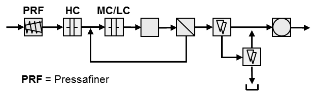
Fig. 4. Early RMP process with second stage LC refining and reject fed back to LC refining; redrawn from Eberhardt (1956)
The process concept in which reject is fed back to second stage main line refining has also been utilized in HC refining processes (Ulander 1985). In that case, a reject dewatering system is still necessary and quality control is quite complicated. Using an LC refiner in this position is advantageous because the primary stage pulp quality can be controlled on-line before it is mixed with the reject.
Processes with second stage main line LC refining are not common for production of TMP for printing papers. One of the few processes with HC-LC main line refining in operation is located in the Holmen Paper Braviken Mill (Norrköping, Sweden) (Sandberg et al. 2017a). However, for hardwood chemi-thermomechanical pulp, it is a common practice nowadays to install second stage LC refining (Guangdong et al. 2011; Peng et al. 2018).
Mechanical pulping lines traditionally have a reject separation and treatment system that includes screens and sometimes hydrocyclones (cleaners), reject dewatering, and refining (Fig. 3). The reject process contains many chests and auxiliary drives (pumps, agitators, reject dewatering, screw conveyors, etc.). A reject system with HC refining contributes to a large part of the investment and maintenance cost for mechanical pulping lines and needs a lot of space. This part of the process could be minimized to reduce the capital, variable, and maintenance costs.
Other than the lower number of unit operations, the HC-LC-S system has several advantages compared with a conventional TMP process; the process is easier to control because the time delay is reduced due to fewer chests, it has a higher availability, and it requires less maintenance because of less equipment.
In this work, the HC-LC-S process concept was evaluated in continuous operation with two different primary HC refiner types: single disc (SD) and DD.
EXPERIMENTAL
Mill Trials
Trials were done to evaluate the HC-LC-S process on a mill scale using TMP lines in the Holmen Paper Braviken Mill. The raw material used was Norway spruce that contained approximately 30% sawmill chips for all of the trials. New pipes were installed in one of the three screen-rooms to be able to feed screen reject back to the chest before the LC refiner, as is shown in Fig. 5b. For clarity, auxiliary equipment, such as plug screw feeders and steam separators, were omitted from the block diagrams in Figs. 5 and 6. The process parameters for all of the trials are shown in Table 1.
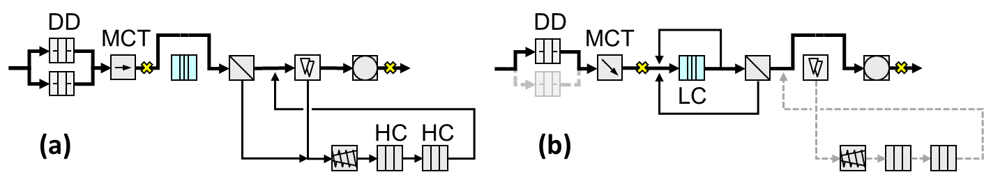
Fig. 5. (a) Reference process, DD+SD-SD; (b) DD-LC-S trial configuration; during the trial, only one DD refiner was in operation, but the production rate from the MC tower (MCT) was higher, i.e., the level of the MCT decreased; sampling points are marked by![]()
The process setup during the reference and first HC-LC-S trials (Andersson 2011) is shown in Fig. 5. Two parallel RGP68DD HC double disc refiners (Valmet, Espoo, Finland) supplied pulp to the LC refiner (TwinFlo72, Andritz, Graz, Austria) and reject system. The TF72 LC refiner has been described in more detail by Andersson (2011). The pulp from the DD refiners was diluted to an 8% consistency in a standpipe after each DD refiner, and then pumped to the LC refiner feed tank, where it was diluted further. After main line refining, the pulp was screened in two Alstrom F4 screens (0.15 mm slots and Gladiator rotors) (Aikawa AFT, Iwaki, Japan) and fractionated with AM80F hydrocyclones (Kadant Noss, Westford, USA). The mixed reject was refined with two HC refiners in series (RGP262, Valmet).
Reference trial
During the reference run, the pulp from the DD refiners bypassed the LC refiner (Fig. 5a). The trial is hereafter denoted as DD+SD-SD, where the left part of the notation is the main line and the right part is the reject line, which are separated by a plus sign. Thus, the DD+SD-SD process configuration contained single stage DD main line refining and two-stage SD HC refining in series in the reject line. Both DD refiners were in operation, which rendered a total production rate of 21 adt/h. The production rate over the reject refiners was 6.9 adt/h. During the reference and first trial runs, the DD refiners had DN72N816 segments (Valmet) and the RGP262 refiners had 262627ABO813 segments (Valmet).
Trial with DD chip refiners
During the first trial (Fig. 5b), hereafter denoted as DD-LC-S, only one DD refiner was running at a production rate of 10.5 adt/h, but the production rate to the LC-S system was 15 adt/h (i.e., the level decreased in the pulp tower after the DD refiners). This was necessary to get an optimum production rate to the screens. The LC refiner had LemaxX segments 72TA203/204 (Andritz). After main line refining, the pulp was screened, and the accept pulp bypassed the hydrocyclone system and was then fed to the disc filters, as is shown in Fig. 5b. The screen reject was fed back to the chest before the LC refiner. The final pulp was supplied to the paper machine during standard newsprint production.
Trial with SD chip refiners
In 2015, the TMP mill was restructured, and the LC refiner and reject system (Fig. 5a) was supplied with pulp from four parallel single stage RLP58 refiners (Valmet).
During the second trial, hereafter denoted as SD-LC-S, three of the four primary RLP58 refiners were running, which resulted in a production rate of 12 adt/h (Fig. 6). The RLP58 refiners were equipped with P59271 segments (Valmet) and were manually adjusted to the set-point for blow line pulp freeness and consistency. For this trial, the screen accept did not bypass the hydrocyclone system because it was anticipated that the shives content would be too high. No data was collected for the final pulp produced from this trial.
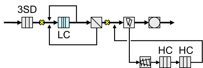
Fig. 6. SD-LC-S trial configuration; sampling points are marked with ![]()
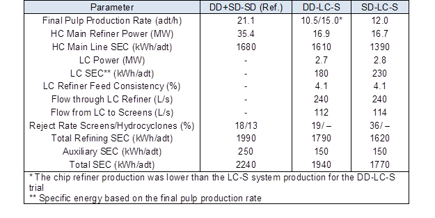
Table 1. Process Parameters
Analyses
All of the samples were taken as composite samples over 10 min. Three sub-samples were taken from each composite sample. The presented data are the average of the three analyses. The following analytical methods were used: hot disintegration ISO 5263-3 (2004) and Canadian standard freeness (CSF) ISO 5267-2 (2001). The tensile index ISO 1924-2 (2008) and specific light scattering coefficient ISO 9416 (2009) were measured on handsheets made with a Rapid Köthen sheet former (Rycobel, Deerlijk, Belgium) ISO 5269-2 (2004). The length-weighted average fibre length and shives content were measured with a PulpEye pulp analyser (PulpEye, Örnsköldsvik, Sweden).
RESULTS AND DISCUSSION
A mechanical pulping process with reduced complexity that consisted of single stage HC refining, followed by LC refining and screening was evaluated. Two types of HC chip refiners, DD and SD refiners, were evaluated and compared with a DD+SD-SD process (reference trial). It was not possible to optimize or make strict comparisons at exactly the same pulp properties for the configurations studied.
Double disc refining can be more efficient than what was possible at the time of the DD-LC-S trial presented here. Therefore, data from Sandberg et al. (2017b) has been included in figures as a comparison. In that trial, chips were pretreated with sodium sulphite and then refined with feeding segments at a high production rate before LC refining. That configuration is denoted as CPT-DD-LC, where CPT denotes chip pretreatment. Data from Sandberg et al. (2017a) has also been included as a comparison to a process with only HC SD refining (denoted as SD-SD+SD-SD). Data from primary and secondary stage main line refining as well as final pulp is presented.
The reject thickening in the screens was lower for the DD pulp compared with the trial with SD pulp at a certain volumetric reject rate, most likely because of the lower fibre length and lower shives content of the DD pulp. Even though the reject flow was reduced to a minimum, the reject consistency was lower compared with the trial with the SD pulp. The lower screen reject consistency was possible because of the fact that the DD pulp was fed to the system at a higher consistency, 8% compared with 5% for the SD trial, and thereby a consistency of 4.1% to the LC refiner was attained. The screen mass reject rate was 19% for the DD trial and 36% for the SD trial.
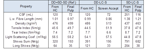
The pulp properties for the two trials are shown in Table 2. Figure 7a displays the tensile index versus specific refining energy for the two trials studied, the reference process, as well as the CPT-DD-LC and SD-SD+SD-SD processes. For each data set, the pulp from the primary HC refiners is represented by the point down to the left. Circled points represent final pulps that were used for paper production. The tensile index increase over the LC-S system was 9.8 Nm/g and 7.4 Nm/g for the SD-LC-S and DD-LC-S trials, respectively. Pulp produced from the DD-LC-S process had a somewhat higher tensile index and pulp produced from the SD-LC-S process had a somewhat lower tensile index compared with the reference process (DD+SD-SD). The specific refining energy was approximately 200 kWh/adt lower for the DD-LC-S process compared with the reference process (Fig. 7). Additionally, the auxiliary specific energy was 100 kWh/adt lower for the HC-LC-S processes.
Table 2. Pulp Properties
It was not possible to conclude which of the two HC-LC-S processes had the highest efficiency (i.e., the process that required the lowest specific energy to reach a certain tensile index) because the tensile index level of the screen accepts was different. With the production level and available LC refining capacity, it was not possible to reach as high a tensile index level with the SD-LC-S process as with the DD-LC-S process. To reach the tensile index level of 52 Nm/g (the level of newsprint pulp in Braviken, Sweden) with the SD-LC-S process, it would have been necessary to reduce the production over the three HC refiners, which most likely would have reduced the process efficiency.
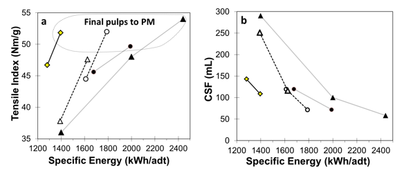
Fig. 7. Specific refining energy vs. tensile index (a) and freeness (b); dashed black line represents the change in the tensile index or freeness from the primary HC refining to screen accept; the solid black line is the second stage LC refining; the grey lines represent the HC refining; the specific energy is only for refining; circled points in (a) represent the final pulps that were used for paper production
Both HC-LC-S processes rendered pulps with lower light scattering values than the reference, but the DD-LC-S pulp was only two units lower (Fig. 8a).
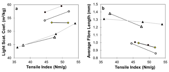
Fig. 8. Tensile index vs. light scattering coefficient (a) and length weighted average fibre length (b); fibre length reduction was somewhat higher for the LC-S processes (dashed lines) compared with the HC reject refining systems (grey lines)
The DD-LC-S pulp had a higher light scattering than the SD-SD+SD-SD pulp. All of the DD pulps had lower fibre lengths than the SD pulps (Fig. 8b). The fibre length reduction was somewhat higher for the LC-S processes compared with the HC reject refining systems.
Figure 9a shows that the DD pulps had a lower total shives content compared with the SD pulp, which made it possible to reach a shives content for the DD-LC-S process similar to that of the reference final pulp. In contrast, the pulps produced with both HC-LC-S processes had a content of long shives (> 1.5 mm) that was similar to that of the reference process with HC refining (Fig. 9b). However, the total number of shives was high for the SD-LC-S system (Fig. 9a). Thus, DD refining was more suitable for the HC-LC-S process. No optimization of the segment design was made for the TF72 LC refiner, which meant that it might be possible to improve the shives removal of the LC-S system. In these trials, screening was done in one stage. However, it is most likely better for both shives reduction and fibre length preservation to do screening in two stages.
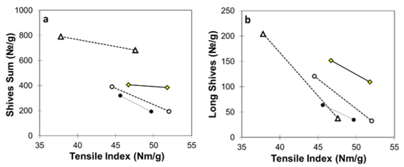
Fig. 9. Tensile index vs. total shives (a) and long shives (> 1.5 mm) contents (b)
The DD-LC-S process eliminated a number of unit operations compared with the reference process, including hydrocyclones, the screw press for reject dewatering, the two HC reject refiners and the reject screen, as well as bow screens, plug screws, and the steam separators after the HC reject refiners. Three chests with agitators and pumps, as well as other auxiliary equipment were also eliminated. The auxiliary specific energy used was 150 kWh/adt for the HC-LC-S processes and for the reference, it was approximately 250 kWh/adt.
The DD-LC-S process required 1940 kWh/adt total specific energy (refining and auxiliary energy) for news-grade TMP. For the reference DD+SD-SD process, the total specific energy used was 2240 kWh/adt. The efficiency of the DD-LC-S process can be improved further if the DD refiners are operated with feeding segments at higher production rate and by using sulphite pretreatment, as was reported by Sandberg et al. (2017b).
Designing an HC-LC-S Process
In this section, some important issues that should be considered when designing an HC-LC-S process is described. A preferable process design for an HC-LC-S process is shown in Fig. 10.

Fig. 10. An example of an HC-LC-S process design
The results from this study have shown that it is preferable to use high intensity primary HC refining, such as DD refining, for an HC-LC-S process because of the high light scattering and low shives content after primary refining. Earlier works have also shown that high intensity refiners, such as RTS (Retention time, Temperature, Speed) and DD refiners, have higher energy efficiencies and produce pulp with a higher light scattering, as well as a lower shives content compared with SD refiners (Sabourin et al. 1997; Andersson et al. 2012a; Ferritsius et al. 2016; Sandberg et al. 2017a).
The HC stage needs to be designed for a relatively low discharge freeness because a high freeness reduction over the LC-S system is not recommended. A too large freeness decrease over the system requires several LC refiners, which would make the investment cost similar to that of a conventional HC refining process. Moreover, a share of the fibre development that is too large in the LC stage reduces the final level of light scattering (Ferritsius et al. 2016; Sandberg et al. 2017a). A freeness decrease of approximately 100 mL is probably suitable, i.e., the freeness from chip refiners should be approximately 200 mL to reach a final pulp freeness of 90 mL to 100 mL (for newsprint type of paper). For higher quality paper, the primary HC refining freeness value has to be lower.
The HC refiner(s) should have a small dilution system after each refiner, such as a standpipe, to be able to have an on-line pulp analyser before the pulp is mixed with the screen reject. If an automatic pulp quality control system is installed, a small standpipe reduces the time delay (Blanchard and Fontebasso 1993). The standpipe should have a MC consistency (7% to 10 %) to attain a good consistency control before the LC refiner. After the standpipe, it is beneficial to have a larger chest to handle shorter stops in the process. The consistency of the pulp coming out from the chest feeding the LC refiner is controlled with dilution right before the feed pump. No conventional latency chest is needed because latency is effectively removed by LC refining (Welch 1999; Ferritsius et al. 2016).
The next stage in the process is LC refining, which in this case is operating as a combined second main line stage and reject refiner. Using an LC refiner in this position is advantageous because the primary stage pulp quality can be controlled on-line after the standpipe before it is mixed with the screen reject. The feed pulp quality to the LC refiner can be measured and the outlet quality can thus be controlled. It is also an advantage to co-refine the primary stage pulp with the reject because a higher load can be applied to a coarser pulp in the LC refiner (Sandberg et al. 2009; Andersson et al. 2012b; Miller et al. 2017).
It is important to optimize the segment designs for the LC stage. Pulps from starts and stops mixed with screen reject can cause plugging of the refiner segments. It is preferable to have two LC refiners in series, as is shown in Fig. 10, with a focus on shives reduction in the first stage and fibre development in the second stage (Luukkonen 2014). After LC refining, the pulp can be fed directly to the screen feed pumps.
The LC refining should preferably be done at a high temperature of approximately 80 °C and pH of approximately 7 to maximize the refiner load with a minimum fibre length reduction (Engstrand et al. 1990; Hammar et al. 2010). However, from mill experience at Braviken, Sweden, a temperature that is too high can cause cavitation in the LC refiner feed pump.
Some important aspects regarding the final stage (screening) should be mentioned. Screening should have a high shives removal efficiency, but fibre length fractionation that is not too strong. If fractionation is too efficient, the fibre length reduction over the LC-S stage can be high (Rubiano Berna et al. 2018). Also, screening should preferably be done in two stages to achieve a good balance between shives removal and fibre length fractionation. Screening can be done at a LC (~1.5%) or HC (~3%). If HC screening is used, the disc filter can be omitted and the amount of white water that is circulating will be minimized. An LC-S system with HC screening is utilized in Skogn Mill, Norway (Mörseburg et al. 2013).
CONCLUSIONS
A process concept inspired by PI principles was evaluated in mill scale continuous operation. The process consisted of single stage HC chip refining, followed by LC refining and screening. The screen reject was led back to the LC refiner, which thereby functioned as a combined second main line stage and reject refiner.
Two types of primary HC refiners were evaluated, SD and DD. It was shown that high intensity chip refining (DD refining in this case) is more suitable than SD refining for the HC-LC-S process because of the higher tensile index and light scattering, as well as the lower shives content.
The specific refining energy was approximately 200 kWh/adt lower for the DD-LC-S process compared with the DD+SD-SD reference process. Additionally, the auxiliary specific energy was 100 kWh/adt lower for the HC-LC-S processes because of less equipment compared to the reference process. The DD-LC-S process required a total specific energy of 1940 kWh/adt for news-grade TMP, which was 300 kWh/adt lower than that for the reference process.
The tensile index and shives content of the pulp produced from the DD-LC-S process were similar to that from the reference process, but the fibre length and light scattering were somewhat lower.
With the HC-LC-S process design, a number of unit operations and auxiliary equipment were eliminated compared with the reference process.
ACKNOWLEDGEMENTS
The authors are grateful to the Knowledge Foundation, the Swedish Energy Agency, and Holmen Paper AB for the financial support. This work was performed within the research program “Energy Efficient Mechanical Pulping” at FSCN, Mid Sweden University.
REFERENCES CITED
Andersson, S. (2011). Low Consistency Refining of Mechanical Pulp – Process Conditions and Energy Efficiency, Licentiate Thesis, Mid Sweden University, Sundsvall, Sweden.
Andersson, S., Sandberg, C., and Engstrand, P. (2012a). “Comparison of mechanical pulps from two stage HC single disc and HC double disc – LC refining,” Appita J., 65(1), 57-62.
Andersson, S., Sandberg, C., and Engstrand, P. (2012b). “Effect of long fibre concentration on low consistency refining of mechanical pulp,” Nord. Pulp Pap. Res. J. 27(4), 702-706. DOI: 10.3183/NPPRJ-2012-27-04-p702-706
Blanchard, P., and Fontebasso, J. (1993). “Mill implementation of a freeness – Specific energy control strategy for high consistency refiners,” in: Proceedings of the International Mechanical Pulping Conference, Oslo, Norway, pp. 215-244.
Bonham, J. S., Flowers, A. G., and Schofield, A. J. (1983). “Post refining of P. radiata TMP,” Appita J. 36(6), 466-470.
Eberhardt, L. (1956). “Wider scope of groundwood from wood chips,” Paper Trade J., 30-33.
Engstrand, P., Hammar, L.-Å., Htun, M., Pettersson, R., and Svensson, B. (1990). “Framställning av mekanisk och kemimekanisk massa i två steg [Preparation of mechanical and chemical mechanical pulp in two steps],” Swedish Patent No. 8801731-4.
Ferritsius, R., Sandberg, C., Ferritsius, O., Rundlöf, M., Daniel, G., Mörseburg, K., and Fernando, D. (2016). “Development of fiber properties in full scale HC and LC refining,” in: Proceedings of the International Mechanical Pulping Conference Jacksonville, FL, pp. 609-628.
Guangdong, Y., Xu, E. C., Jozic, D., and Fitz, M. (2011). “P-RC APMP lines at SUN paper group,” In: Proceedings of the International Mechanical Pulping Conference, Xian, China, pp. 165-169.
Hammar, L.-Å., Salmén, L., Sandberg, C., and Sundström, L. (2010). “The effect of process conditions on pulp quality development in low consistency refining of mechanical pulp-TMP,” Appita J. 63(5), 377-380.
ISO 1924-2 (2008). “Paper and board – Determination of tensile properties – Part 2: Constant rate of elongation method (20 mm/min),” International Organization for Standardization, Geneva, Switzerland.
ISO 5263-3 (2004). “Pulps – Laboratory wet disintegration – Part 3: Disintegration of mechanical pulps at > 85 degrees C,” International Organization for Standardization, Geneva, Switzerland.
ISO 5267-2 (2001). “Pulps – Determination of drainability –Part 2: ‘Canadian Standard’ freeness method,” International Organization for Standardization, Geneva, Switzerland.
ISO 5269-2 (2004). “Pulps – Preparation of laboratory sheets for physical testing – Part 2: Rapid-Köthen method,” International Organization for Standardization, Geneva, Switzerland.
ISO 9416 (2009). “Paper — Determination of light scattering and absorption coefficients (using Kubelka-Munk theory),” International Organization for Standardization, Geneva, Switzerland.
Luukkonen, A. (2014). “LC refining of high freeness CTMP,” in: Proceedings of the International Mechanical Pulping Conference, Helsinki, Finland.
Miller, M., Luukkonen, A., and Olson, J. A. (2017). “Effect of LC refining intensity on fractionated and unfractionated mechanical pulp,” Nord. Pulp Pap. Res. J. 32(3), 386-394. DOI: 10.3183/NPPRJ-2017-32-03-p386-394
Mörseburg, K., Imppola, A., Johansson, L., and Ertsås P. A. (2013). “Effects of inlet pulp quality and specific energy consumption in mill-scale low consistency refining of mechanical pulp,” in: 8th International Fundamental Mechanical Pulp Research Seminar, Åre, Sweden, pp. 21-23.
Peng, F., Xing, J., Olsson, G., Nåvik, J., and Granfeldt, T. (2018). “High quality eucalyptus CTMP for board grades at Stora Enso Beihai mill,” in: Proceedings of the International Mechanical Pulping Conference, Trondheim, Norway.
Rubiano Berna, J. E., Sandberg, C., Martinez, D. M., and Olson, J. A. (2018). “Theoretical study of systems composed of low consistency refining and pressure screening,” in: Proceedings of the International Mechanical Pulping Conference, Trondheim, Norway.
Sabourin, M., Xu, E., Cort, B., Boileau, I., and Waller, A. (1997). “Optimizing residence time, temperature and speed to improve TMP pulp properties and reduce energy,” Pulp Pap.-Canada 98(4), 38-45.
Sandberg, C., Berg, J.-E., and Engstrand, P. (2017a). “Low consistency refining of mechanical pulp – System design,” Tappi J. 16(7), 419-429.
Sandberg, C., Berg, J.-E., and Engstrand, P. (2017b). “Mill evaluation of an intensified mechanical pulping process,” Nordic Pulp Pap. Res. J. 32(2), 204-210. DOI: 10.3183/NPPRJ-2017-32-02-p204-210
Sandberg, C., Berg, J.-E., and Engstrand, P. (2017c). “Process intensification in mechanical pulping,” Nordic Pulp Pap. Res. J. 32(4), 615-622. DOI: 10.3183/NPPRJ-2017-32-04-p615-622
Sandberg, C., Sundström, L., and Nilsson, L. (2009). “Potential of low consistency refining of TMP – Mill evaluation,” in: Proceedings of the International Mechanical Pulping Conference, Sundsvall, Sweden, pp. 186-189.
Stankiewicz, A. I., and Moulijn, J. A. (2000). “Process intensification: Transforming chemical engineering,” Chem. Eng. Prog., 22-34.
Strand, B. C., Mokvist, A., Falk, B., and Jackson, M. (1993). “The effect of production rate on specific energy consumption in high consistency chip refining,” in: Proceedings of the International Mechanical Pulping Conference, Oslo, Norway, pp. 143-151.
Ulander, E. (1985). “Double benefit – economy and quality – with twin refiners at Hylte Bruks AB,” in: Proceedings of the International Mechanical Pulping Conference, Stockholm, Sweden, pp. 120-127.
Van Gerven, T., and Stankiewicz, A. (2009). “Structure, energy, synergy, time – The fundamentals of process intensification,” Ind. Eng. Chem. Res. 48(5), 2465-2474. DOI: 10.1021/ie801501y
Welch, L. V. S. (1999). Low Consistency Refining of Mechanical Pulps, Ph.D. Dissertation, University of British Columbia, Vancouver, Canada.
Article submitted: September 26, 2018; Peer review completed: November 18, 2018; Revised version received and accepted: November 29, 2018; Published: December 7, 2018.
DOI: 10.15376/biores.14.1.882-894