
Abstract
The processing temperature of poly(ethylene terephthalate) waste (rPET) and ultra-high molecular weight polyethylene (UHMWPE) was lowered by blending to avoid decomposition of rice husk fiber (RHF) during the manufacturing of wood plastic composite (WPC). Maleic anhydride (MA) grafted blends of HDPE/LDPE/UHMWPE-g-MA and rPET/LDPE-MA were prepared. Those blends were flowable at 240 °C. They were employed as blended matrices to make HDPE/LDPE/UHMWPE-g-MA/rPET/LDPE-MA/RHF wood composite at processing temperatures not exceeding 240 °C. The study of RHF loading on the WPC performance revealed that melt flow index (MFI) and mechanical performances measured by impact, flexural, and tensile properties were weakened, but heat distortion temperature (HDT) was enhanced at high RHF loading. When the stabilizer content did not exceed 2 phf, the toughness and ductility were improved. Surface treatment of RHF by MA and dicumyl peroxide (DCP) enhanced the interfacial surface adhesion, but the toughness and ductility of the WPC were reduced at high MA/DCP dosing. The formation of crosslink structure via peroxide free radical initiated reaction at the MA grafted branch chains was the prime suspect for the inferiority of the mechanical performances.
Download PDF
Full Article
Manufacturing of Wood Plastic Composite from Polyethylene/Poly(ethylene terephthalate) Waste/Ultra High Molecular Weight Polyethylene Blends and Rice Husk Fiber: Raw Materials Preparation and Preliminary Processing Investigation
Utai Meekum
The processing temperature of poly(ethylene terephthalate) waste (rPET) and ultra-high molecular weight polyethylene (UHMWPE) was lowered by blending to avoid decomposition of rice husk fiber (RHF) during the manufacturing of wood plastic composite (WPC). Maleic anhydride (MA) grafted blends of HDPE/LDPE/UHMWPE-g-MA and rPET/LDPE-MA were prepared. Those blends were flowable at 240 °C. They were employed as blended matrices to make HDPE/LDPE/UHMWPE-g-MA/rPET/LDPE-MA/RHF wood composite at processing temperatures not exceeding 240 °C. The study of RHF loading on the WPC performance revealed that melt flow index (MFI) and mechanical performances measured by impact, flexural, and tensile properties were weakened, but heat distortion temperature (HDT) was enhanced at high RHF loading. When the stabilizer content did not exceed 2 phf, the toughness and ductility were improved. Surface treatment of RHF by MA and dicumyl peroxide (DCP) enhanced the interfacial surface adhesion, but the toughness and ductility of the WPC were reduced at high MA/DCP dosing. The formation of crosslink structure via peroxide free radical initiated reaction at the MA grafted branch chains was the prime suspect for the inferiority of the mechanical performances.
DOI: 10.15376/biores.18.1.1293-1329
Keywords: Wood plastic composite; MA grafted blended matrices; Processing Temperature; Performance Properties
Contact information: Institute of Engineering, Suranaree University of Technology, Maung, Nakorn Ratchasima, Thailand; *Corresponding author: umsut@g.sut.ac.th
GRAPHICAL ABSTRACT
INTRODUCTION
For the material science aspect, wood-plastic composites (WPCs) are materials manufactured from thermoplastics reinforced with natural fibers. For industrial applications, they are used as a substitute or alternative for natural wood, the usage of which is widely prohibited or legally controlled by many countries. Building and decorative materials, such as outdoor decks, floors, windows, and doors, are found to be their main applications. Polyolefins, such as poly(vinyl chloride) (PVC), poly(propylene) (PP), and poly(ethylene) (PE), are commonly used as matrices. In science and engineering considerations, there are advantages and disadvantages to these WPC matrices. For example, PP is easy to process, but it has a low ultraviolet radiation (UV) resistance. The PE offers decent melt processing, but it has a low service temperature. The PVC has an outstanding resistance to environmental deterioration, but it is harmful to operator due to the emitted toxic fume during melt extrusion. There have been many research studies and attempts to overcome these weaknesses.
There are numerous reports on PP/wood flour WPC made with various wood flour particle sizes (Hubbe and Grigsby 2020). The mechanical properties of composites depend on the fiber aspect ratio (Stark and Rowlands 2003). Additionally, the effect of fiber types on the mechanical properties of WPCs were studied and published (Zaini et al. 1996; Febrianto et al. 2006; Khan et al. 2009). Improving their long-term properties by grafting, crosslinking and matrix blending, fiber modification, and adding high performance fillers were among the most typical methods that were studied and found in previous literature (Bengtsson and Oksman 2006; Lei et al. 2007; Clemons 2010). Silane grafting followed by a water crosslink reaction of the polymer matrix to form a loosely macro crosslink chain, especially with PP and PE, has received much attention in both industrial applications and fundamental research. The chemical mechanism of the crosslink reaction was demonstrated (Zhou et al. 2009). The published work has revealed that macroscopic crosslinking can provide obvious advantages, such as easy processing, low capital investment, and favorable properties in the processed materials (Sirisinha and Kawko 2005; Meekum and Khongrit 2018). Vinyl silane was chemically grafted onto the polymer chain by free radicals using peroxide as an initiator. Then, it was hydrolyzed and condensed to create –Si–O–Si– bonds between the chains and/or bonding between the wood and polymer. The macro crosslink, via silane bridges, results in outstanding performance properties (Meekum 2014; Meekum and Kingchang 2017).
The flammability, fracture toughness, and impact resistance of WPCs are important for different bending loaded applications. To achieve the highest load bearings possible, various modifications such as toughening of the matrix with a stiffer polymer, rubber toughening, hybridization of the natural fiber with engineering reinforcement, and/or filling with inorganic particles have been studied (Hristov et al. 2004). Polymer blends have been successful in improving the properties of WPCs such as impact strength, tensile strength, environmental stress cracking, low temperature impact properties, and more. (Wang et al. 1995; Pearson et al. 2000; Lei and Wu 2010; Sudár et al. 2016; Zadeh et al. 2017). Treatment or modification of the fiber/filler is one of the main ways to enhance the properties of WPCs (Schirp et al. 2014; Koohestani et al. 2017).
The usage of environmentally friendly materials and the circular economy are current mega trends for industrial product marketing, especially for interior and exterior construction applications. Accordingly, the utilization of polymeric waste and cellulosic fiber by-product from agro-industry for manufacturing of WPC have gained attention by both researchers and industries especially for the bio-circular green economic concept (Adhikary et al. 2008; Leu et al. 2012; Chen and Ahmad 2017).
In this research, WPC was manufactured from the polymer blends of virgin high density PE(HDPE)/low density PE(LDPE)/poly(ethylene terephthalate)(PET) obtained from drinking bottle waste, which was toughened with ultra-high molecular weight PE (UHMWPE) and reinforced with rice husk fiber (RHF). UHMWPE and PET are known as high melting temperature polymers. Processing temperatures over 300 °C are typically employed. RHF, a type of cellulosic fiber, is easily decomposed at a critical temperature above 250 °C. Hence, in the manufacturing of WPC having PET, UHMWE, and RHF as main ingredients, lowering the processing temperature of PET and UHMWPE without thermal decomposition of RHF was one of the main important challenges of the research work. The matrix blending innovation was the key to overcoming those challenges. Preparation and characterization of the blended matrices raw material were evaluated, reported, and justified in this work. One of the ambitious industrial applications from this work is interior and exterior construction products manufactured by extrusion processes. The basic research procedures to obtain the most appropriate WPC formulation, both mechanical performance and economic aspects, were also included in this publication.
EXPERIMENTAL
Materials
Polymeric materials
Commercial blown film grade HDPE (HD7000F) was kindly supplied by PTT Global Chemical Plc. (Bangkok, Thailand). LDPE (LD1905F) was kindly supplied by SCG Chemical Co. Ltd. (Bangkok, Thailand). Both PEs were employed for matrices blending. PET flake from post-consumer drinking bottles were collected from a local disposal site (Nakorn Ratchasima, Thailand). It was machine shredded into small flakes and thoroughly cleaned by detergent water. It was denoted as rPET. UHMWPE (SUNFINE UH900) as toughener was supplied from Asahi Chemical Industry Co., Ltd. (Osaka, Japan). The recommended melt processing temperatures and HDTs for the polymeric materials employed in this work are summarized in Table 1.
Filler, fiber reinforcement, and additives
The talc filler (Jetfine® 8CF) with the averaged particle size of 1.1 µm was supplied from Imerys Talc Luzenac France (Luzenac sur‐Ariège, France). Dicumyl peroxide (DCP) was employed as a free radical initiator. It was supplied by Thai Poly Chemical Ltd. (Sumutsakorn, Thailand). 99% purity maleic anhydride (MA) as co-initiator was purchased from Acros Organics (Glee, Belgium). A mixed powder at 1:1 by weight containing Tris(2,4-di-tert-butylphenyl) phosphate (Irgafos 168) and Octadecyl 3-(3,5-di-tert-butyl-4-hydroxyphenyl) propionate (Inganox 1076) was employed as the heat/processing stabilizer. Those two chemicals were supplied from Ciba Specialty Chemicals Corp (Tarrytown, NY, USA). All chemicals employed were used as received. Rice husk hull from a local rice mill (Nakorn Ratchasima, Thailand) was ground into a fine powder rice husk fiber (RHF) with a hammer mill machine. The RHF was obtained and collected via a sieving machine with the mesh size ranging from 100 – 500 microns. The RHF was vacuum dried at 105 °C for at least 3 h prior to melt compounding into WPC.
Table 1. Summary of the Recommended Melt Processing Temperature for HD7000F, LD1905F, UHMWPE (SUNFINE UH900), and PET

HDPE/LDPE/UHMWPE-g-MA and rPET/LDPE-g-MA preparation
Table 2 summarizes the formulation and also batch size for preparing HDPE/LDPE/UHMWPE-g-MA and PET/LDPE-g-MA as the matrices blends of the WPC in this work. For the HDPE/LDPE/UHMWPE-g-MA melt compounding, the calculated batch size quantity of 1000 g of HDPE, 500 g of LDPE, 12.0 g of MA pellet, and 1.2 g of DCP was placed in a sealed plastic bag. The mixture of ingredients was placed in the oven at 100 °C for 2 min. After MA and DCP were completely liquidized, the plastic pellets mixture were immediately transferred into a high-speed mixer chamber (LabTech Engineering Co., Ltd, Samutprakarn, Thailand). Then, 400 g of talc and 250 g of UHMWPE powder were added into the chamber. All solid ingredients were mixed inside the high-speed mixer chamber for 2 min at approx. 5,000 rpm. The polymer pellets mixture was then constantly fed via a single screw feeder into a co-rotation twin screw extruder equipped with a section of three triple kneader disks and 25 mm in diameter and L/D = 20 screws (Brabender Model PL2100; Brabender®GmbH & Co. KG, Duisburg, Germany). The barrel temperature profiles were electrically controlled at 230, 240, 250, 265, and 230 °C, from the feed to die zones, respectively. The screw speed was constantly controlled at 25 rpm. The extrudate strand was cooled by air blowing.
Table 2. Blending Formula of (a) HDPE/LDPE/UHMWPE-g-MA and (b) rPET/LDPE-g-MA

For the rPET/LDPE-g-MA preparation, similar compounding procedures were adopted. rPET flake was vacuum dried at 100 °C for 8 h prior to melt compounding. The calculated batch size consisted of 1000 g of vacuum dried rPET flake, 500 g of LDPE, 5.0 g of MA pellet, and 0.50 g of DCP. These were placed in a sealed plastic bag. Then, the ingredient was placed in the oven at 100 °C for 2 min. After MA and DCP were completely liquidized, the mixture ingredient was immediately transferred into a high-speed mixer chamber and vigorously mixed for 2 min. The polymer pellets mixture was then melt compounded on a co-rotation twin screw extruder at barrel temperature profiles of 230, 240, 250, 265, and 230 °C, from feed to die zones, respectively. The rPET/LDPE-g-MA strand was cooled and pelletized.
WPC manufacturing and specimen preparation
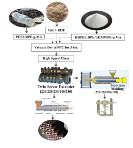
The WPC manufacturing was performed on a twin screw compounder as schematically summarized in Fig. 1. In accordance with the designed WPC formulation, the solid mixture comprised of HDPE/LDPE/UHMWPE-g-MA, rPET/LDPE-g-MA, RHF and talc was pre-blended and vacuum dried at 90 °C for 3 h. Then, it was vigorously mixed by a high-speed mixer. The solid ingredient was then constantly fed via single screw feeder into a co-rotation twin screw extruder at the barrel temperature profiles of 220, 225, 230, 240, and 230 °C from feed to die zones, respectively. The melt compounding was achieved at a screw speed of 25 rpm. The resultant WPC strand was cooled down and pelletized. The wood composite pellet was lowered in moisture content at 90 °C in a vacuum oven for 3 h before injection molding into a standard test specimen. The injection molding machine, CLF-80T (Chuan Lih Fa Machinery Works Co. Ltd., Tainan, Taiwan), was employed. The barrel temperature profile was electrically controlled at 190, 200, 210, and 220 °C from the feed to nozzle zones, consecutively. The mold temperature was set at 45 °C with a cooling time of 25 s. The obtained test specimens were annealed at atmospheric room temperature for 24 h prior to performing testing.

Fig. 1. Schematic diagram for manufacturing WPC and test specimens
Material Characterization and Testing
The mechanical properties include three-point flexural bending, tensile, and Izod impact strengths (both notched and unnotched modes). Testing was carried out in accordance with ASTM D790-10 (2010), ASTM D638 (2014), and ASTM D256-10e1 (2010), respectively. A universal testing machine (Instron Model 5565, Norwood MA, USA) with load cell of 5 kN was employed. The flexural span length at 80 mm and crosshead speed of 15 mm/min were assigned. The standard test specimen size of 3.2 mm x 12.7 mm x 125 mm was used. For the tensile testing, the strain rate at 15 mm/min by means of the crosshead speed was also electronically controlled. The ASTM Type I dumbbell shape standard specimen made from the above injection molding process was employed. The pendulum impact testing machine (Instron Ceast Model 9050) equipped with striking impactors was employed. The impactor having the striking energy of 2.16 and 11.0 Joules was used for notched and unnotched impact strength measurements, respectively. The injected molded standard test specimen size of 3.2 mm x 12.7 mm x 60 mm was employed. The V-notch on the sample was made by using the standard notching machine.
The heat distortion temperature (HDT) was examined using an Atlas testing machine (HDV1, Atlas Material Testing Technology LLC, Mount Prospect, IL, USA), and ASTM D648-07 (2007) was followed with a 455-kPa standard load. The exact specimen dimension to those flexural testing was employed. The melt flow index (MFI) was performed in accordance with ASTM D1238-13 (2013) using a Kayeness melt flow indexer (Dynisco, Inc., Franklin, USA) at 230, 240 or 250 °C and 5.0 kg load. The durability of the RHF wood samples by means of % water absorption and % thickness swelling after 1- and 7-day water submersion periods, were measured in accordance with ASTM D570-98(2010)e1 (2010). The specimen having the identical dimension to the unnotched impact testing was employed. The morphological observation by mean of scanning electron microscope (SEM) was conducted at the accelerating voltage of 15 keV (JSM 6400, JEOL, Tokyo, Japan). The Mettler Toledo TGA/DSC1, Star System (Schwerzenbach, Switzerland) was used to measure the decomposition temperature (Td) of RHF. The IR spectra at 1 cm-1 resolution was acquired on the thin film sample. The T27/Hyp2000 FTIR was equipped with attenuated total reflection (ATR) sampling technique (Bruker Scientific LLC, MA, USA).
RESULTS AND DISCUSSION
Characterization and Testing of Raw Materials
The main raw materials for manufacturing WPC were HDPE/LDPE/UHMWPE-g-MA, rPET/LDPE-g-MA, RHF, and talc. They were in-house prepared. One of the main challenges for this innovative research was utilizing as low a processing temperature as possible, without sacrificing the mechanical properties, to manufacture WPC from high processing temperature polymeric matrices to avoid fiber reinforcement decomposition. As summarized in Table 1, the recommended processing temperature of PET and UHMWPE is normally above 300 °C. However, the degradation temperature (Td) of cellulosic natural fiber is typically below 240 °C. On the fiber with high lignin content, the Td below 200 °C is common. Accordingly, the upper limit melt compounding temperature for manufacturing WPC from high melting point polymer matrices with the natural fiber reinforcement is restricted by its Td. Thermal decomposition of natural fiber during WPC manufacturing will cause dramatic mechanical/physical properties deterioration. One of the alternative solutions to overcome this processing burden is by compatible blending the high melting point polymer matrix with low melting point polymer constituent as adopted in this work. By such a method, the flow ability, compatibility, and mechanical properties of the resultant blends and eventually the final WPC product must be confirmed by testing.
Figure 2 shows the TGA thermogram of RHF reinforcement and talc filler employed in this work. The Td window of RHF was 200 to 250 °C. Above 250 °C, the RHF decomposition process indicated by the weight loss was obviously observed. The allowed upper limit for processing of RHF as reinforcement for WPC manufacturing must be below 250 °C. For the talc filler, the TGA thermogram revealed that the employed talc filler showed no sign of the weight loss at temperatures up to 400 °C.
Figure 3 contains micrographs of the hammer mill ground RHF and talc filler employed for manufacturing the WPC. The fiber lengths of the ground RHF ranged from 145 to 500 m. Rice hull fiber was the main composition of RHF. For the talc filler, the thin flat flake with an approximate width of 10 m was visualized.

Fig. 2. TGA thermogram of ( ) RHF and (- -) Talc Filler

Fig. 3. SEM Photos of (a) RHF and (b) Talc filler
For the polymer processing aspect, MFI is the most common and basic melt flowability or rheological measurement of polymer under the static torque loading. It is a fundamental material parameter used by polymer engineers to select the most suitable processing method to fabricate the polymeric into product. Table 3 summarizes the flowability measured as MFI at 5.0 kg standard load with the assigned melting temperatures at 230, 240, and 250 °C.
Table 3. MFI Test Result at the Given Temperature of the Raw Material for WPC

HDPE and LDPE melted and flowed at all given temperatures, but very low flowability of rPET was observed at only the melt temperatures above 250 °C. In contrast, UHMWPE indicates no flow (NF) at all assigned temperatures. These MFI results confirmed that the processable temperature of rPET and UHMWPE employed as matrix and toughener, respectively, for manufacturing the WPC in this study must be higher than 250 °C. Especially for the UHMWPE, melt processing temperature beyond 300 °C must be engaged.
For the rPET/LDPE-g-MA blend, the MFI of 0.021 g/10 min was observed at 240 °C and it was increased to 7.332 g/10 min at 250 °C. Hence, the minimum processable temperature of the rPET/LDPE-g-MA blend at 240 °C was suggested. Similarly, the HDPE/LDPE/UHMWPE-g-MA blend at 240 °C was at 0.056 g/10 min and it marginally increased to 0.073 when the melt temperature was increased to 250 °C. For the screw operated polymer processing machines, melting is induced by conduction heat (heated barrel) and viscous heat induced by torque shearing between screw/polymer and fluid/barrel during the screw revolution. This is the main and important source of melting energy. For such thermodynamic principle, melt compounding of the WPC comprised of rPET/LDPE-g-MA, HDPE/LDPE/UHMWPE-g-MA, and RHF reinforcement to carry out manufacturing on the twin screw extruder at a temperature that does not exceed 240 °C is manageable. Hence, the thermal decomposition of the RHF reinforcement can be avoided.
For the rPET/LDPE-g-MA blend, the MFI of 0.021 g/10 min was observed at 240 °C and it was increased to 7.332 g/10 min at 250 °C. Hence, the minimal processable temperature of the rPET/LDPE-g-MA blend at 240 °C was suggested. Similarly, the HDPE/LDPE/UHMWPE-g-MA blend at 240 °C was at 0.056 g/10 min, and it marginally increased to 0.073 when the melt temperature was increased to 250 °C. For the screw operated polymer processing machines, melting is induced by conduction heat (heated barrel) and viscous heat induced by torque shearing between screw/polymer and fluid/barrel during the screw revolution is the main and important source of melting energy. For such thermodynamic principle, melt compounding of the WPC comprised of rPET/LDPE-g-MA, HDPE/LDPE/UHMWPE-g-MA, and RHF reinforcement to manufacture on the twin screw extruder at a temperature that does not exceed 240 °C is manageable. Hence, the thermal decomposition of the RHF reinforcement can be minimized.
Infrared Analysis
Both the HDPE/LDPE/UHMWPE-g-MA and rPET/LDPE-g-MA blends were manufactured via single-step melt compounding on the twin screw extruder. Then, the MA would be randomly grafted onto individual polymer chains. The presence of MA-grafted polymer chains was characterized by FTIR. The possible unreacted MA residual in the blends was removed by precipitation method prior to conducting the test. The polymer blend was dissolved in hot xylene and then precipitation in methanol. The FTIR spectra at the wave number 1750 to 2000 cm-1 of HDPE/LDPE/UHMWPE-g-MA and HDPE, and rPET/LDPE-g-MA and LDPE are presented in Fig. 4(a) and 4(b), respectively.
The strong asymmetric C=O stretching at 1791 cm-1 was obviously apparent in the HDPE/LDPE/UHMWPE-g-MA spectra. Also, a medium intensity peak attributable to symmetric C=O stretching at 1867 cm-1 was evidenced. These two IR peaks are the most commonly seen for unsaturated cyclic anhydrides such as maleic anhydride. In rPET/LDPE-g-MA spectra, the C=O stretching at 1791 and symmetric C=O stretching at 1867 cm-1 were also in evidence with relatively lower intensity than the spectra found in the HDPE/LDPE/UHMWPE-g-MA. The interference of strong C=O stretching from the ester group from rPET would be the main reason for lowering the C=O anhydride peaks intensity. Obeying these IR characterization results, it could be suggested confidently that the MA was grafted onto the polymer chains in both HDPE/LDPE/UHMWPE-g-MA and rPET/LDPE-g-MA blends.

Fig. 4. FTIR spectra (a) HDPE/LDPE/UHMWPE-g-M and (b) rPET/LDPE-g-MA
Scanning Electron Microscopy
Miscibility or compatibility is a prime engineering aspect in polymer blends, especially when blending two different generic polymers. SEM is the most common method to observe blend morphology. Figures 5(a) and 5(b) are the SEM photos of HDPE/LDPE/UHMWPE-g-MA at X400 and X1000 magnification, respectively. The HDPE/LDPE/UHMWPE-g-MA blend shows the homogenous material. It is absolute miscible blends. The photos also reveal the “fibril like skin” fracture traces of the UHMWPE toughener. Figures 5(c) and 5(d) are fracture surface SEM photos of rPET/LDPE and rPET/LDPE-g-MA blends at X1000 magnification, respectively. The phase separation between rPET and LDPE was obvious on the rPET/LDPE blend. This evidence indicated poor compatibility between rPET and LDPE. However, for the rPET/LDPE-g-MA blend, homogenous disbursement of very tiny LDPE droplets within the rPET as major continuous phase was evident. This SEM information supported that better compatibility between rPET and LDPE blend can be enhanced by the MA grafting process.

Fig. 5. SEM Photos of polymers blended matrix (a) HDPE/LDPE/UHMWPE-g-MA at X400, (b) HDPE/LDPE/UHMWPE-g-MA at X1000, (c) rPET/LDPE at X1000, and (d) rPET/LDPE-g-MA at X1000, respectively
Effect of RHF Contents on WPC Performance
RHF is an agroindustry waste that is abundantly available. For the economic and ecological point of view, utilizing this cellulosic waste as high quantity as possible into WPC and commercializing the wood composite as construction material is one of the high value-added challenges. Nevertheless, for the sake of mechanical performance, the optimal matrix to fiber reinforcement ratio is one of the prime considerations for manufacturing of the WPC material. By employing the rPET/LDPE-g-MA and HDPE/LDPE/UHMWPE-g-MA blended matrices at 50:50 weight ratio in the WPC manufacturing, the RHF reinforcement contents ranged from 30 to 50 phr corresponding to the total weight of the blended matrices were initially investigated. 20 phr of talc filler was equally added into each formulation. Five WPC formulations as demonstrated in Table 4 were assigned. The WPC specimen was successfully compounded and then injection molded at temperatures that did not exceed 240 °C.
Table 4. WPC Formulations with Various RHF Contents

Figure 6 illustrates the fractured surface SEM photos of the WPC reinforced with RHF at the contents of 30, 35, 40, and 50 phr. The fine fibril-like traces were visualized on the matrix phase of the WPC. This fibril scar resulted from the presence of UHMWPE toughener that was blended in the HDPE/LDPE/UHMWPE-g-MA matrix. Also, there was no obvious indicator for the phase separation within the blended matrices. There was no doubt that the matrix surface area portion was reduced upon increasing the RHF reinforcement loading. The fiber pull-out or fiber break down footprints were also observed on the fractured surface. With closer observation at the RHF/matrices interface bonding, the SEM photos revealed that reasonably good surface adhesion between RHF and the MA-grafted blended matrices was established. Nevertheless, the diminishment of surface adhesion seemingly occurred when the RHF reinforcement contents were increased, especially at 50 phr of RHF loading. The effect of reinforcement overloading of RHF on the WPC material would be suspected. RFH has the lowest bulk density in comparison to other polymeric and filler ingredients. Then, for the volumetric quantity consideration on the obtained WPC at 50 phr and above of RHF, the volume fraction of RHF must be much higher than the polymeric fraction.

Fig. 6. SEM at X400 magnification for WPC reinforced with (a) 30 phr (b) 35 phr, (c) 40 phr, and (d) 50 phr of RHF
Regarding the basic “rule of mixtures” for mechanical performance consideration of the composite material, lower mechanical performance of RHF must be the domain fraction of the manufactured WPC. Accordingly, material performance inferiority especially for the mechanical properties would be experienced.
Flow ability of the manufactured WPC at melt temperatures not exceeding 250 °C was one of the main challenges of this work. Figure 7 shows the measured MFI at 230/5.0 of the WPC reinforced with 30 to 50 phr of RHF, respectively. For the first instance, under the static shear loading at 5.0 kg, all of the manufactured WPC samples had ability to flow at 230 °C melt temperature.

Fig. 7. MFI at 230/5.0 of WPC reinforced with 30 to 50 phr RHF contents, respectively
Obviously, the measured MFIs of the WPC pellet under the static shear loading were evidently low. Upon increasing the RHF contents from 30 to 50 phr, the MFIs were undoubtedly reduced from approx. 0.054 to 0.028 g/10 min. For the short fiber reinforced thermoplastic composite materials, the flow ability of the molten composite is typically retarded or resisted by the quantity and also the size of fiber reinforcement. Therefore, increasing in the melt viscosity (lowering in MFI) is commonly found when the fiber loading and/or fiber size is increased. Nevertheless, the obtained MFI values are preferably and manageably handled by extrusion based processors as typically adopted for the industrial manufacturing process of the WPC products.
HDT is the common parameter to verify the upper limit service temperature of polymeric products. In the production of items from WPC materials, PE matrix is generally categorized as having good toughness but low service temperature. Outdoor applications at temperatures above 50 °C would not be recommended for PE-based WPCs. In this work, HDT at 455 kPa standard load was performed on the manufactured WPC specimens at the RHF loading from 30 to 50 phr, and the results are presented in Fig. 8.
As expected, HDT gradually increased from 79.1 to 90.5 °C when the RHF loading was increased from 30 to 45 phr, respectively. HDT decreased by a few degrees at 50 phr of RHF loading. In the composite material with sufficient matrix/fiber interfacial adhesion, the HDT is typically enhanced by increasing the reinforcement loading. However, the upper limit enhancement would be overcome by the matrix/fiber adhesion droughting effect provoked by the “fiber overloading” of the material. According to the above SEM analysis, good surface adhesion between (rPET/LDPE-g-MA)/(HDPE/LDPE/UHMWPE-g-MA) blended matrices and RHF at 30 to 40 phr loading were manifested. Therefore, HDT improvement with the RHF loading of the manufactured WPC could be theoretically explained. By overloading RHF at 50 phr, the interfacial bonding was diminished and hence the upper limit of HDT was established. As for the engineering and commercial applications consideration, the maximum service temperature, by means of HDT, of the (rPET/LDPE-g-MA)/(HDPE/LDPE/UHMWPE-g-MA) wood composite reinforced with 45 phr of RHF was at approx. 90.5 °C. This figure would be far more acceptable for this WPC to be commercialized as the construction material for both interior and exterior applications.

Fig. 8. HDT of WPC at various RHF contents
Fracture toughness under accelerated force/energy striking of the (rPET/LDPE-g-MA)/(HDPE/LDPE/UHMWPE-g-MA)/RHF wood composites test specimens having the RHF contents from 30 to 50 phr were characterized by notched and unnotched impact strengths. The test results versus the RHF contents were plotted and are presented in Fig. 9. It can be seen that the notched impact strengths marginally declined from 1.67 to 1.47 kJ/m2 when the RHF loading was increased from 30 to 50 phr. The exact trend, reducing from 6.07 to 4.24 kJ/m2, was clearly apparent for the unnotched impact strength test results. For unfilled or unreinforced polymeric materials, the dissimilarity trend between notched and unnotched impact strength is commonly manifested as notched sensitive phenomenon. As for composite materials design, the notched sensitive effect would be commonly resolved by reinforcing the material with high stiffness fiber. Polyethylene is not categorized as notched sensitive material. According to the impact strengths data obtained from the (rPET/LDPE-g-MA)/(HDPE/LDPE/UHMWPE-g-MA)/RHF wood composites, the weakening of the impact strengths with increasing the RHF loading would have a two- fold explanation. RHF is a highly brittle reinforcement material. Accordingly, the toughness, by means of impact strength especially tested on the notched mode, of the manufactured wood composites must be reduced at high RHF loading. Also, as justified from SEM characterization, the interfacial adhesion between blended matrices and RHF seem to be diminished at high RHF loading. As such events, the impact strengths inferiority of the wood composites was experienced when the RHF reinforcement contents were overloaded.

Fig. 9. Impact strengths of WPC at various RHF contents
The rupture strength by means of three-point bending flexural testing was performed on the injection molded (rPET/LDPE-g-MA)/(HDPE/LDPE/UHMWPE-g-MA)/RHF wood composites specimens. The flexural strength, modulus and deformation at break values versus RHF loading were obtained and graphically presented in Figs. 10(a) and 10(b), respectively. From the test results, it can be seen that the flexural strength gradually declined from 32.34 to 25.05 MPa when the RHF loading was increased from 30 to 50 phr, respectively. In contrast, the flexural modulus increased from 1.729 to 2.063 GPa with increasing of the assigned RHF contents. For the deformation at break, it obviously declined from 4.13 to 2.64 mm with increasing the RHF contents. Generally, the flexural toughness is a measurement of energy absorption capacity of material and is also used to characterize the crack resistance of material.
Unlike impact toughness, the flexural test is conducted under constant bending rate. For composite materials, fiber reinforcement normally acts as an energy absorber or dispersion during crack propagation. Therefore, flexural toughness improvement is commonly achieved when tough fiber is employed as the reinforcement on the composite materials. Flexural toughness or energy absorption capacity of material is mathematically interpreted from the integrated area of load versus displacement flexural testing profile. For the given material, lowering of the flexural strength and deformation at break but rising of the flexural modulus is typically interpreted as flexural toughness incompetency. Regarding the obtained flexural properties, it can be concluded that the flexural toughness/ductility of the manufactured wood composites gradually deteriorated while increasing the RHF loading. This statement was in good agreement with the above impact toughness results. Again, RHF brittleness and exhausting in the interfacial adhesion at high RHF loading must be taken for explanation.

Fig. 10. (a) Flexural strengths and modulus, and (b) deformation at Break of the WPC at the given RHF contents, respectively
The tensile properties by means of strength, modulus and strain at break of the short fiber reinforced composites (SFRC) manufactured from (rPET/LDPE-g-MA)/(HDPE/ LDPE/UHMWPE-g-MA)/RHF were performed at the strain rate of 50 mm/min. The obtained test results were plotted against RFH contents and presented in Figs. 11(a) and 11(b), respectively. Similar to those reported flexural properties, the ultimate tensile strength and strain at break were significantly decreased from 16.75 to 4.56 MPa and 1.51 to 0.34% when the RHF contents were increased from 30 to 50 phr, accordingly. Vice versa, the tensile modulus gradually increased from 2.903 to 3.218 GPa with increasing the RHF loading, consecutively.
For the SFRC materials, the mechanical performance by means of tensile property is basically justified by matrix/fiber volume fraction, fiber aspect ratio, fiber orientation, interfacial adhesion, etc. For well randomized SFRC manufactured from the same fiber, matrix and processing conditions, the tensile performance of the composite material must be mainly controlled by matrix/fiber volume fraction and interfacial adhesion. From the tensile characteristic outcomes found from the WPC produced in this publication, strength and strain at break weakening but modulus rising upon increasing the fiber loading, it could be interpreted that the toughness/ductility under tension force loading of the SFRC material were falling at high RHF content. As repeatedly stated in impact and flexural toughness conclusions and also reinforcingly justified by SEM evidence, the brittleness of RHF and diminishing of the interfacial adhesion upon increasing the reinforcement loading must be the main causes of this tensile performance deterioration.

Fig. 11. (a) Ultimate tensile strengths and modulus, and (b) strain at break of the WPC versus RHF contents, respectively
Scientific and engineering knowledge findings were not only the main research interests of this research work but also the transfer of innovative knowledge for the commercial application was also much more ambitiously attempted. Short term and long-term durability consideration of the WPC products for the exterior function would be equally, or perhaps more, important to mechanical performances. In this work, the short-term durability by means of % water/moisture absorption and % dimensional swelling in the course of 1- and 7-days water immersion was conducted. Figures 12(a) and 12(b) are the plots of % absorption and % swelling versus RHF contents of the (rPET/LDPE-g-MA)/(HDPE/LDPE/UHMWPE-g-MA)/RHF wood composites, respectively. For the % water absorption, as shown in Fig. 12(a), the results show that 1- and 7-days absorption were marginally increased from 0.24 to 0.30 % and 0.35 to 0.42% when RHF loading was increased from 30 to 50 phr, respectively.

Fig. 12. Plots of (a) Moisture absorption, and (b) % swelling of the WPC reinforced with RHF at various contents, respectively
At the given RHF content, there was no doubt that 7 days absorption was significantly greater than 1 day immersion. The marginal uprising trend for % absorption with RHF contents could be explained by hydrophilicity and interfacial bonding depletion. RFH is a cellulosic natural fiber. It is commonly hydrophilic in nature. Therefore, % water absorption of the WPC would be more favorable when increasing the RHF dosing. As suggested in SEM and mechanical assessments, the interfacial adhesion between RFH and the blended matrices was weakened at high RHF loading. Then, the micro gaps at the interfacial contact would likely be formed. Accordingly, the water absorption induced by the capillary action from the micro gaps would occur. Eventually, the water uptake of the WPC would be favored at high RHF loading. In contrast, the (rPET/LDPE-g-MA) and (HDPE/LDPE/UHMWPE-g-MA) blended matrices, as the major component for the WPC material, are hydrophobic polymers. With good mixing via the twin screw melt compounding, the entire RHF reinforcement would be thoroughly coated with the blended matrices. Hence, the water absorption onto the cellulosic RHF could be retarded. As such, % water absorption of the (rPET/LDPE-g-MA)/(HDPE/LDPE/UHMWPE-g-MA)/RHF woods composite samples would be unquestionably minimized, as indicated by the test results. Similar trends were observed for the % swelling figures. Both 1 and 7 days % swelling values did not exceed 0.4%, and they were ambiguously increased with increasing the RHF contents. Additionally, the difference between 1 and 7 days % swelling was very minimum. Obeying the standard deviation of error (SD) values as attached in the plot, they could be emphasized, without bias, that there was no significant dimensional change of the WPC products upon prolong immersion in water for 1 and 7 days. This statement could be explained by the fact that an extremely low degree of water absorption on the WPC specimen was observed. Thus, there was not enough hydro static pressure/force to dimensionally expand the WPC specimen. Consequently, % swelling of the WPC caused by water absorption should be minimized.
The effect of the RHF loading, from 30 to 50 phr, on the performances of (rPET/LDPE-g-MA)/(HDPE/LDPE/UHMWPE-g-MA)/RHF woods could be preliminary concluded. SEM data revealed the diminishing in the fiber/matrix surface adhesion at high RHF loading. The flow ability of the WPC was retarded by the quantity of RHF. But manageable flow could be achieved at melt temperatures below 240 °C. The service temperature, HDT, of the wood composite was enhanced by increasing the fiber loading. The maximum HDT was obtained at 45 phr of RHF. The mechanical performances by means of impact, flexural and tensile properties were weakened at high RHF loading. The brittleness of RHF and diminishing in the interfacial bonding at high reinforcement loading were the main causes of this deterioration. Further performance improvements of the WPC were explored, and these will be discussed later.
Effect of Thermal/Processing Stabilizer
The powder form of Irgafos 168 and Inganox 1076 are commercially available thermal/processing stabilizers. They are commonly used in polymer processing industries. Irgafos 168 is well known as a thermal and hydrolytic antioxidant. It is called a “thermal stabilizer” by polymer processors. Inganox 1076 is a discoloring stabilizer that is intended to deal with overheating/decomposition during melt processing. Thus, it is generally classified as “processing stabilizer”. For high stabilizing efficiency concern, the combined Irgafos 168 and Inganox 1076 is recommended. The typical properties of these stabilizers given by the manufacturer are summarized in Table 5. Both stabilizers had Td up to 300 °C and less toxicity. According to the water solubility values shown, they indicate that both chemicals are hydrophobic and Irgafos 168 has higher hydrophobicity than Inganox 1076. In this work, the mixed thermal/processing stabilizers at 1:1 by weight were prepared and employed. Figure 13 demonstrates the TGA thermogram of RHF and RHF incorporated with 1% of the thermal/processing stabilizer. Regarding the obtained TGA result, it was seen that the initial Td of RHF without stabilizer was approx. 200 °C. Meanwhile, the initial Td of RHF with 1% stabilizer was shifted to higher temperature at approx. 220 °C. This shifting could be indicating that the thermal/processing stabilizer prepared by mixing Irgafos 168 and Inganox 1076 at 1:1 weight ratio would be efficiently used to retard the thermal decomposition process of RHF and increase the initial Td by approx. 20 °C. Note that the main aim of this research work was to manufacture the WPC, without scarifying the mechanical performances, at the processing temperature below the Td of RHF reinforcement. Additionally, rPET and UHMWPE were purposely included into the blended matrices because they were categorized as circular economic material and toughener, respectively. Both materials typically require processing temperatures above 300 °C. Therefore, “how to manufacture the WPC having rPET, UHMWPE and RHF as the ingredients at compounding temperatures do not exceed Td of RHF” was the main challenge for this research study. Thermal stabilization of the RFH reinforcement by incorporated with the thermal/processing stabilizer was one of the additional procedures that was explored. The RHF was vigorously mixed with the assigned amount of the stabilizer in the external mixer at 120 °C for 5 min prior to use as reinforcement in the WPC manufacturing.
Table 5. Typical Properties of Irgafos 168 and Inganox 1076


Fig. 13. TGA thermogram of ( ) RHF and (- -) RHF+1% thermal/processing stabilizer
Table 5 summarizes the WPC formulations reinforced with the thermal/ processing stabilized RHF. The stabilizer contents, corresponding to the weight of RHF, varied from 0 to 4.0 phf (part per hundred part of fiber), respectively. A total of five WPC formulations were designed and compounded. The RFH and talc filler loading were constantly assigned at 45 and 20 phr, correspondingly. The rPET/LDPE-g-MA and HDPE/LDPE/UHMWPE-g-MA blends at weight ratio of 50:50 were employed as blended matrices. The total compounding batch size for each formulation was 495 g. The temperature during compounding on twin screw and specimen injection molding was carefully monitored and controlled at well below 240 °C.
Table 6. WPC Formulations with Varied Thermal/Processing Stabilizer Contents

Figure 14 shows the SEM photos taken from the fracture surfaces of the WPC reinforced with RHF mixed with thermal/processing stabilizer at 0, 2, 3, and 4 phf, respectively.

Fig. 14. SEM Photos of the fractured surface of WPC reinforced with RHF contained the stabilizer at the contents of; (a) 0, (b) 2, (c) 3, and (d) 4 phf, respectively
According to the obtained SEM photos, it can be seen that the interfacial adhesion between RHF and the polymer blended matrices was reasonably good at 0, 2, and 3 phf of stabilizer dosing, respectively. However, at 4 phf, the gap between RHF and the matrices was clearly visualized. In addition, smooth RHF surface without adherence of matrices was observed at high stabilizer loading. This SEM evidence would manifest that the loaded stabilizer could act as “interfacial bonding retardant” between RHF and (rPET/LDPE-g-MA) and (HDPE/LDPE/UHMWPE-g-MA) blended matrices. This statement could be supported by the material data shown in Table 5 that Inganox 168 has high hydrophobicity. But the cellulosic RHF is a hydrophilic fiber. Hence, at high stabilizer loading, the stabilizer breaching from RHF could have occurred. Consequently, it could have weakened the interfacial bonding between the blended matrices and the RHF.
The plot of MFI versus the thermal/processing stabilizer dosing onto the RHF reinforcement from 0 to 40 phf is shown in Fig. 15. At 230 °C melting temperature, the manufactured WPCs were manageable to flow at very low flowrate, approx. 0.050 g/10 min. Also, the measured MFIs were noticeably decreased with increasing of the stabilizer loading. This declining trend outcome could suggest that the possible thermal decomposition on RHF at high processing temperature was hindered by adding the thermal/processing stabilizer. This was because, in general, the thermal decomposition of the cellulosic natural fiber during the WPC manufacturing not only would cause the product discoloration and surely reinforcing capability, but the process could also have a chain-reaction effect on chain degradation of the polymer matrix. Consequently, the physical appearance, rheological properties, and the mechanical performance degradation of the composite material must have occurred. Upon chain scission induced by the thermal decomposition of the fiber reinforcement, the decreasing in the melt viscosity, increasing in the MFI must be involved. Obeying the MFI and TGA results found in this session, it could be justified that the thermal decomposition of RHF was retarded by employing the thermal/processing stabilizer and then there was no significant sign of matrices chain degradation induced by the thermal decomposition chain reaction.

Fig. 15. MFI against stabilizer contents from 0 to 4 phf, respectively
The service temperatures by means of HDT for the manufactured (rPET/LDPE-g-MA)/ (HDPE/LDPE/UHMWPE-g-MA)/RHF wood composite at the assigned thermal/ processing stabilizer contents from 0 to 4 phf were characterized and are graphically reported in Fig. 16.

Fig. 16. HDT plot of the WPCs produced by incorporating thermal/processing stabilizer at 0 – 4 phf, respectively
The marginal reduction in the HDT from 91.1 to 89.5 °C was observed when the stabilizer loading was increased from 0 to 4 phf. There were pros and con effects for employing the stabilizer onto the WPC ingredients, as postulated earlier. Certainly, adding the stabilizer onto the WPC compound would prevent or retard the thermal decomposition of RHF. On the other hand, overloading of the stabilizer would cause the chemical breaching and then ruin the RHF/matrices interfacial bonding. Then, the material performance would be diminished. In general, for the composite material with good interfacial adhesion and at assigned reinforcement loading, HDT of the material is typically regulated by the matrix performance. Due to retardancy on the RHF decomposition, resulting in no chain deterioration of the blended matrices, there would be no significant changes on the HDT of the obtained wood composite. However, noticeable reduction in HDT at 4 phf loading could be justified by the stabilizer breaching effect.
Figure 17 summarizes the notched and unnotched impact strengths plot of the wood composites produced from RHF reinforcement treated with 0 to 4 phf of the thermal/processing stabilizer, respectively. For the notched impact strength regarding the SD of the test results, small increases from 1.48 to 1.59 kJ/m2 were noticed when the stabilizer dosing was increased from 0 to 2 phf. With further loading from 3 to 4 phf, the notched impact strengths were ambiguously reduced at around 1.54 kJ/m2. Similar trends but with obvious changes were seen on unnotched impact strengths. The unnotched impact strengths of the WPCs were improved from 3.12 to 5.34 kJ/m2 when the stabilizer contents were increased from 0 to 2 phf. Again, the impact strengths reversely went down to 4.54 kJ/m2 upon further increase of the content to 4 phf. These impact test results, especially for the unnotched ones, could emphasize the previous propositions about pros and con effects of the employed stabilizer. With the optimal stabilizer loading, reinforcement and then matrices deterioration must be thermally stabilized. Then, the mechanical performance must be improved. However, the chemical breaching would be experienced if the wood composite was overdosed with the stabilizer. Then, the mechanical performance must be reduced. Regarding these obtained impact strengths, it could be suggested that the optimal thermal/processing stabilizer loading for manufacturing the (rPET/LDPE-g-MA)/ (HDPE/LDPE/UHMWPE-g-MA)/RHF wood composite was 2 phf. Overdosing the stabilizer onto the WPC ingredient resulted in mechanical weakening due to the chemical breaching effect.

Fig. 17. Notched and unnotched impact strengths of the WPC produced by incorporating thermal/processing stabilizer at 0 to 4 phf, respectively
Fracture toughness by means of three-point bending flexural measurement was conducted on the WPC specimens. The results were plotted against the thermal/processing stabilizer loading, as presented in Fig. 18(a) and 18(b), respectively. Like the impact strengths discussion, the flexural strength and modulus were apparently increased, 23.59 to 26.78 MPa for strength and 2.018 to 2.120 GPa for modulus, when the stabilizer contents were increased from 0 to 2 phf, respectively. After that, the declining trend was observed upon increasing the loading to 4 phf. For the deformation at break values, they were also noticeably increased from 2.69 to 3.27 mm by increasing the stabilizer from 0 to 2 phf. When the loading exceeded 2 phf, there was no further significant change on the deformation at break. Once again, increases in flexural strength, modulus, and deformation at break are principally translated as rupture toughness improvement. Vice versa, the low ductility material must be interpreted. Obeying these principles and the obtained flexural characteristics, it could be pointed out that the optimal thermal/processing stabilizer loading for manufacturing the (rPET/LDPE-g-MA)/ (HDPE/LDPE/UHMWPE-g-MA)/ RHF wood composite was 2 phf. Interfacial bond strength deterioration caused by the stabilizer breaching was the main effect on the rupture toughness failure when the loading did exceed 2 phf.

Fig. 18. (a) Flexural strengths and modulus and (b) deformation at break of the WPC contained 0 – 4 phf of thermal/processing stabilizer, respectively.
The tensile characteristics of the WPC by means of ultimate strength, modulus, and strain at break were carefully conducted at the constant strain rate of 50 mm/min. Plots of the obtained tensile properties versus the thermal/processing stabilizer loading are illustrated in Fig. 19(a) and 19(b), respectively. The ambiguous tendency of the ultimate strength improvement, from 9.01 to 9.29 MPa, was noticed when the stabilizer loading was increased from 0 to 2 phf. With further addition of the stabilizer up to 4 phf, the strength was apparently reduced. For the tensile modulus, the marginally inclining trend was indicated. A similar trend with strength was seen for the strain at break results. The maximum strain at break at 0.71% was recorded when 2 phf of the stabilizer was added onto RHF. Again, the decline in the strain at break was revealed when the stabilizer dosing exceeded 2 phf. The obtained tensile properties results suggest that the ductility of the manufactured WPC was faintly improved by adding the thermal/processing stabilizer onto RHF at the loading content when it did not exceed 2 phf. Overloading of the stabilizer beyond 2 phf showed a negative effect on the WPC ductility.

Fig. 19. Plots of (a) Ultimate tensile strengths and modulus, and (b) strain at break of the WPC having 0 to 4 phf stabilizer contents, respectively
The exact explanation, as earlier mentioned, is as follows. Within the optimal stabilizer dosing, less than 2 phf, the thermal decomposition process of the cellulosic RHF and the chain degradation of the blended matrices caused by the generated heat of decomposition reaction could be inhibited. Consequently, the tensile properties were maintained or perhaps improved by the reinforcement capacity of the RHF. A chemical or stabilizer breaching phenomenon could occur by overloading of the thermal/processing stabilizer. Then, the weakening in the matrices/RFH interfacial bonding would be established. Subsequently, the declining of tensile ductility must be suffered.
Considering the effect of the thermal/processing stabilizer, prepared from mixed Irgafos 168 and Inganox 1076, on the mechanical performance of the (rPET/LDPE-g-MA)/ (HDPE/LDPE/UHMWPE-g-MA)/RHF wood composite, it could be concluded that 2 phf dosing was the maximum and optimal content. The toughness and ductility of the manufactured WPC were noticeably improved. Overloading of the stabilizer, beyond 2 phf, onto the RHF had caused the chemical breaching effect that ruined the fiber/matrix interfacial bonding strength of the composite material. An observed failure in mechanical capability was the main consequence.
Figure 20 shows the effect of the thermal/processing stabilizer loading on the durability of the WPC by means of % moisture absorption and % dimensional swelling upon prolonged water immersion for 1 and 7 days.

Fig. 20. (a) % Moisture absorption and (b) % swelling of the WPC loaded with 0 to 4 phf stabilizer
The % moisture absorption for both 1- and 7-days immersion was decreased with increasing the thermal/processing stabilizer loading. The stabilizer was coated onto the surface of RHF prior to compounding with the blended matrices. The hydrophobic stabilizer could act as a moisture/water repellant film on the surface of RHF. Consequently, the moisture absorption through the surface of RHF could be prevented. Thus, % moisture absorption must be reduced when the stabilizer loading is increased. Considering the error standard deviation of test, the % dimensional swelling, particularly under prolonged soaking under water for 7 days, was merely changed with the stabilizer contents. Also, the magnitude of % swelling values were very low, approx. 0.3%. As in the previous justification, low % water absorption of the WPC specimen was observed. Thus, there was not enough hydro static pressure/force to dimensionally distort the WPC specimen. Consequently, the % swelling of the WPC caused by water absorption must be negligible. Also, both (rPET/LDPE-g-MA) and (HDPE/LDPE/UHMWPE-g-MA) blended matrices are hydrophobic polymers. Thus, water that diffuses into the WPC specimen must be unfavored. The moisture could only penetrate at thin surface of the wood composite. As such, the dimensional swelling due to the hydro static pressure of the absorbed water must be minimal and, furthermore, % swelling did not change with increasing of the stabilizer loading.
Effect of Maleic Anhydride/Peroxide Treatment
Chemical modification via surface treatment of the natural fibers is commonly performed for manufacturing the composite material including for the WPC. One of the main benefits that resulted from the treatment was the improvement of the fiber/polymer matrix surface adhesion. The different chemicals can be used for surface treatment including alkaline, silane, peroxide, maleic anhydride, etc. (Sooda and Dwivedi 2005). Generally, chemical modification provides more dimensional stability, reduces water absorption capacity, and imparts resistance to fiber against fungal decay. Maleic anhydride (MA) with or without peroxide initiator, especially dicumyl peroxide (DCP), treatment is classified as effective, low cost, and having ease of processing for cellulosic fibers treatment (Shah et. al. 2019). However, in the presence of polyethylene-based matrix, MA induced crosslinked structure within the polymer chains, which is typically found as the side reaction (Montoya-Ospina et al. 2021). Consequently, an increase in the material brittleness commonly occurs. In the present work, the combined MA/DCP was employed as a chemical surface treatment on the RHF reinforcement for manufacturing the WPC having (rPET/LDPE-g-MA) and (HDPE/LDPE/UHMWPE-g-MA) as the blended matrices.
Table 7 summarizes four formulations of the WPC reinforced with MA/DCP-treated RHF. The stabilizer and RHF contents were constantly kept at 1 and 45 phf, respectively. The RHF was treated with MA/DCP at weight ratios of 0.0/0.00 to 2.0/0.20 phf, respectively. The assigned amount of RHF, MA, DCP, and thermal/processing stabilizer were vigorously mixed in an internal mixer at 90 °C for 5 min prior to mixing with the compound and the blended matrices on the twin screw extruder. Injection molding into the test specimen did not exceed 240 °C.
Table 7. WPC Formulation Reinforced with MA/DCP RHF Treated RHFธ

Figure 21 shows the SEM photos taken at the fracture surface of the WPCs manufactured from the treated RHF at 0.0/0.00 to 2.0/0.20 phf of MA/DCP, respectively. The interfacial bonding between RHF and the blended matrices was improved by employing the MA/DCP treated RHF. The obvious matrices/RHF surface bridges were clearly observed when MA/DCP at 1.0/0.10 phf was employed. The perfect matrices/RHF surface bonding was clearly seen by further increasing the MA/DCP loading. This was expected based on the well-established principle that MA can be easily grafted onto cellulosic fiber. Also, polyethylene chain can be promptly grafted with MA via peroxide-initiated free radical reaction. In the present system, the RHF-MA could have formed interfacial chemical bonding with non-grafted units of the PE chains in the blended matrices. Subsequently, perfect interfacial bonding between RHF and the blended matrices, as can be seen from SEM photos, must be accomplished.

Fig. 21. SEM Photos at X400 of WPC manufactured from the RHF treated with MA/DCP at (a) 0.0/0.00, (b) 1.0/0.10, (c) 1.5/0.15 and (d) 2.0/0.20 phf, respectively
The rheological property of the WPC was characterized by means of MFI. The test results versus MA contents were plotted and are presented in Fig. 22. The MFI decreased when RHF was treated with 1.0 phf of MA. When the MA loading was further increased up to 2.0 phf, the MFI was ambiguously decreased with the MA treatment. However, the degree of MFI decreasing was insignificant. There are two hypothetical explanations for the lowering in MFI or for the viscosity increasing of the molten WPC caused by MA/DCP treatment. The chemical surface modification of RHF using MA was the main purpose of this session. The presence of DCP, the interfacial chemical bonding between the treated RHF-MA, and the blended polyethylene chains must be formed. This formation of fiber/matrices chain linkages must retard the flowability of the WPC. Hence, high melt viscosity (low MFI) must be observed. Moreover, under the excessive amount of MA/DCP or perhaps MA/DCP breaching phenomenon, interchain chemical bonding within the blended PE chains induced by peroxide free radical initiated reaction could be followed. Then, a crosslinked structure of the blended PE matrices must be the result. Appropriately, the flowability of the molten WPC must be inhibited. More excessive MA/DCP loading meant a higher crosslink density of the blended PE matrices. The excessive amount of MA/DCP not only influenced the MFI of the manufactured WPC but also negatively influenced the toughness of the material. This statement will be further demonstrated in the following discussion.

Fig. 22. MFI plot of WPC reinforced with RHF treated with MA/DCP at MA contents of 0, 1.0, 1.5, and 2.0 phf, respectively
HDT of the WPC reinforced with the MA treated RHF was measured at 455 kPa standard load. The plot of HDT results versus MA contents is given in Fig. 23.

Fig. 23. HDT plot of the WPC manufactured from the MA treated RHF at 0, 1.0, 1.5, and 2.0 phf, respectively
The service temperature of the wood composite was increased from 83.9 to 92.7 °C when the RHF reinforcement was treated with 1.0/0.01 phf of MA/DCP. The declining trend was visually observed when further increasing of MA loading to 2.0 phf. As earlier mentioned, the improvement of HDT via RFH treatment with MA/DCP was preliminarily attributed to the enhancement of fiber/matrices interfacial bonding and the PE chain crosslink formation via the free radical initiated reaction from the excessive MA/DCP loading. Moreover, high crystallinity development of the composite matrix is an additional positive effect on the HDT of the composite material. Typically, these phenomena enhance the thermal resistance capability of composite materials. However, the crystallinity of the blended PE matrices could be diminished upon increasing the degree of crosslink density at high MA/DCP loading (Liu et al. 2014). Hence, the HDT of the WPC reinforced with RHF treated with MA/DCP at 2.0/0.02 phf was in a declining direction.
The fracture resistance capabilities of the WPC characterized by impact strengths testing were evaluated. Figure 24 shows the plot of notched and unnotched impact strengths of the WPC versus the MA loading, correspondingly. According to the test outcomes, it was apparent that both notched and unnotched impact strengths were in the declining trend with increasing the MA/DCP loading. This agrees with the statements that matrices/fiber interfacial bonding enhancement and crosslink density rising of the blended PE matrices were the main causes of the increasing in MA/DCP loading.

Fig. 24. Notched and Unnotched impact strengths of the WPC reinforced with RHF treated with MA at 0, 1.0, 1.5, and 2.0 phf, respectively
Normally, the formal consequence would be the positive effect on the impact strength if high toughness reinforcement was employed. In contrast, the crosslink density of the matrices must have great negative effect on the impact toughness. In this work, RHF is known as a brittle reinforcement by nature. As justified, the impact strengths enhancement due to the matrices/RHF improvement of the wood composite would be minimum. Vice versa, the brittleness characteristic from the crosslinked structure of the blended PE matrices would be conquered. Therefore, the decline of the impact strengths upon increasing the MA/DCP loading on the RHF surface treatment must be seen.
The flexural properties by means of strength, modulus, and deformation at break were tested at the displacement rate of 15 mm/min. The obtained results were plotted against MA contents and presented in Fig. 25. The flexural strength, modulus, and deformation at break gradually decreased when the MA/DCP loading were increasing from 0.0/0.00 to 2.0/0.20, consecutively. These declines in the flexural properties can be interpreted by assuming that the rupture toughness of the manufactured WPC was reduced when the brittle RHF reinforcement was treated with a high amount of MA/DCP. This concept is in good agreement with the above impact strengths results.

Fig. 25. Plots of (a) Flexural strengths and modulus, and (b) deformation at break of the WPC reinforced with RHF treated with MA at 0, 1.0, 1.5, and 2.0 phf, respectively
Domination of brittleness characteristic due to the crosslink structure formation of the blended PE matrices over the interfacial boding enhancement has been repeatedly taken as the explanation. In addition, crystallinity of the blended PE matrices would be reduced when the crosslink density was raised upon increasing of MA/DCP loading. Therefore, the loss of rupture toughness would be further experienced.
Ultimate tensile strength, modulus, and strain at break of the injection molded (rPET/LDPE-g-MA)/(HDPE/LDPE/UHMWPE-g-MA)/RFH wood composite specimens were obtained by tension testing at 50 mm/min rate. The test values versus MA contents were plotted and are illustrated in Fig. 26. The exact trends of those flexural properties were obtained. The tensile strength, modulus, and strain at break were progressively decreased with increasing the MA contents. High magnitude of decreasing for the ultimate strength and strain at break were observed where the RHF was treated with 2.0 phf of MA. The declining trend in the tensile properties upon increasing of MA loading was interpreted as the diminishment of WPC material ductility. As previously postulated, the breached or excessive MA/DCP from the RHF treatment process could initiate the free radical crosslinking reaction on the PE chains from the blended matrices.

Fig. 26. Plots of (a) Ultimate tensile strengths and modulus, and (b) strain at break of the WPC reinforced with the treated RHF at MA contents at 0, 1.0, 1.5, and 2.0 phf, respectively y
The higher the MA/DCP loading, the greater in the crosslink density of the PE chains. Consequently, reducing the wood composite ductility should be established. Regarding the tensile properties obtained from these manufactured WPCs, it could be pointed out that the obvious thermoset characteristic, high crosslink density, of the wood composite was at 2.0 phf of MA loading, where vast reductions of the strength and strain at break were visualized. Nevertheless, the RHF/matrices interfacial bonding enhancement via the MA/DCP treatment could be debated. In fact, good interfacial bonding is one of the advantages of the WPC ductility. Therefore, in comparison with the matrix’s performance, the reinforcing capability of the RHF would have limited contribution to the WPC ductility under tension loading. Then, the suggested conclusion could be drawn that the ductility incompetency of the WPC could be observed when the RHF reinforcement was surface treated with high excess amounts of MA/DCP.
Taken from the mechanical evaluation of the wood composite manufactured from the (rPET/LDPE-g-MA)/(HDPE/LDPE/UHMWPE-g-MA) blended matrices and the surface treated RHF using MA/DCP, it could be concluded that the toughness and ductility capability of the manufactured composite material were gradually reduced upon increasing the MA/DCP loading for the RHF surface treatment. The crosslink structure formation via the peroxide free radical initiated reaction caused by the overloaded MA/DCP was the prime suspect for these deficiencies in mechanical performance. The enhancement of the fiber/matrices interfacial bonding strength was the benefit from the treatment but it did not have sufficient strength to overcome the brittleness capacity of the resulted crosslink or thermoset characteristic of the PE chains in the blended matrices.

Fig. 27. Plots of (a) % moisture absorption, and (b) % swelling of the WPC reinforced with the treated RHF at MA contents at 0, 1.0, 1.5, and 2.0 phf, respectively
The tests for % water absorption and % dimensional swelling after prolonged water immersion for 1 and 7 days were performed. The test results versus the MA contents are graphically presented in Figs. 27(a) and 27(b), respectively. For the % water absorption, without bias, it was noticed that very small digit increasing was visualized, especially for 1-day immersion test, when the RHF was treated with 1.0 phf of MA. However, there was no significant change in the % absorption when the MA contents were further increased. The tested values were almost constant at around 1.4% and 4.6% for 1- and 7-day prolonged immersions, respectively. Meanwhile, the % swelling of the WPC specimen that developed due to the dimensional changing caused by the hydrostatic pressure of the absorbed moisture was almost unchanged regardless of the MA content. In particular, at 1 day of the water immersion, the % swelling was constant at approx. 0.14%. Meanwhile, very tiny magnitudes of % swelling, ranging from 0.46 to 0.51%, were observed after prolonged water immersion for 7 days. Taking both engineering aspects and industrial applications into consideration, the effect of MA/DCP contents on the RHF surface treatment process had insignificant impact on the durability properties of the produced WPC. The moisture resistance and dimensional stability after prolonged water immersion were unchanged.
CONCLUSIONS
- The rice husk fiber (RHF) reinforcement showed a degradation temperature window in the range of 200 to 250 °C. The high-density polyethylene/low-density polyethylene/ ultra-high molecular weight polyethylene-graft-maleic anhydride (HDPE/LDPE/ UHMWPE-g-MA) and recycled (rPET/LDPE-g-MA) blends were successfully prepared as the matrices for manufacturing the RHF-reinforced wood composite. The flowability of the blends at 240 °C melt temperature was verified by melt flow index (MFI) testing. The presence of MA grafting onto the blends was confirmed by Fourier-transform infrared (FTIR) analysis. Perfect miscibility was observed for the HDPE/LDPE/UHMWPE-g-MA blend. The acceptable compatibility of rPET in the rPET/LDPE-g-MA blend was revealed by scanning electron microscopy (SEM).
- The effect of the RHF loading on the performances of composites of (rPET/LDPE-g-MA)/(HDPE/LDPE/UHMWPE-g-MA)/RHF was evaluated. The diminishing in the fiber/matrix surface adhesion at high RHF loading was revealed by SEM analysis. The MFI of the WPCs was reduced by increasing the RHF loading. But they were capable of flow at a melt temperature of 230 °C. The HDTs of the wood composites were enhanced by increasing the fiber loading. The mechanical performances by means of impact, flexural, and tensile properties were weakened at high RHF loading. The brittleness of RHF and diminishing of the interfacial bonding at high fiber loading were the main causes of the toughness deterioration.
- Mixed Irgafos 168 and Inganox 1076 were employed as thermal/processing stabilizers. The toughness and tensional ductility of the (rPET/LDPE-g-MA)/ (HDPE/LDPE/ UHMWPE-g-MA)/RHF wood composite were noticeably improved when the stabilizer content did not exceed 2 phf. The chemical breaching caused by overloading of the stabilizer was the prime suspect for the fiber/matrix interfacial strength weakening and then mechanical weakening of the wood composite material. The stabilizer loading below 2 phf was the suggested optimal dosing.
- Maleic anhydride with dicumyl peroxide (MA/DCP) was used as the surface treatment of RHF. SEM analysis showed good interfacial surface adhesion on the MA/DCP treated RHF. However, it was found that the toughness and tension ductility capabilities of the (rPET/LDPE-g-MA)/(HDPE/LDPE/UHMWPE-g-MA)/RHF composites were gradually reduced upon increasing the MA/DCP loading on the treatment. The crosslink structure formation via the peroxide free radical initiated reaction caused by the overloaded MA/DCP was the prime hypothesis for these losses in mechanical performance. Although the enhancement of the fiber/matrices interfacial bonding strength was a benefit from the RHF treatment, it did not provide sufficient strength to overcome the brittle nature of the resulted thermoset characteristic arising from the crosslinked PE chains.
ACKNOWLEDGMENTS
This work was supported by the Suranaree University of Technology and the Office of Higher Education Commission under the NRU Project of Thailand and patronage of the Institute of Research and Development.
REFERENCES CITED
ASTM D648-07 (2007). “Standard test method for deflection temperature of plastics under flexural load in the edgewise position (withdrawn 2016),” ASTM International, West Conshohocken, PA.
ASTM D256-10e1 (2010). “Standard test methods for determining the izod pendulum impact resistance of plastics,” ASTM International, West Conshohocken, PA.
ASTM D790-10 (2010). “Standard test methods for flexural properties of unreinforced and reinforced plastics and electrical insulating materials,” ASTM International, West Conshohocken, PA.
ASTM D1238-13 (2013). “Standard test method for melt flow rates of thermoplastics by extrusion plastometer,” ASTM International, West Conshohocken, PA.
Adhikary, K. B., Pang, S., and Staiger, M. P. (2008). “Long-term moisture absorption and thickness swelling behaviour of recycled thermoplastics reinforced with Pinus radiata sawdust,” Chemical Engineering J. 142(2), 190-198. DOI: 10.1016/j.cej.2007.11.024
Bengtsson, M., and Oksman, K. (2006). “Silane crosslinked wood plastic composites: Processing and properties,” Compos. Sci. Technol. 66(13), 2177-2186. DOI: 10.1016/j.compscitech.2005.12.009
Chen, R. S., and Ahmad, S. (2017). “Mechanical performance and flame retardancy of rice husk/organoclay-reinforced blend of recycled plastics,” Mat. Chem. and Phy. 198, 57-65. DOI: 10.1016/j.matchemphys.2017.05.054
Clemons, C. (2010). “Elastomer modified polypropylene–polyethylene blends as matrices for wood flour–plastic composites,” Compos. Part A-Appl. S. 41(11), 1559-1569. DOI: 10.1016/j.compositesa.2010.07.002
Febrianto, F., Setyawati, D., Karina, M., Bakar, E. S., and Hadi, Y. S. (2006). “Influence of wood flour and modifier contents on the physical and mechanical properties of wood flour-recycle polypropylene composites,” Journal of Biological Sciences 6(2), 337-343. DOI: 10.3923/jbs.2006.337.343
Hristov, V. N., Lach, R., and Grellmann, W. (2004). “Impact fracture behavior of modified polypropylene/wood fiber composites,” Polym. Test. 23(5), 581-589. DOI: 10.1016/j.polymertesting.2003.10.011
Hubbe, M. A., and Grigsby, W. (2020). “From nanocellulose to wood particles: A review of particle size vs. the properties of plastic composites reinforced with cellulose-based entities,” BioResources 15(1), 2030-2081. DOI: 10.15376/biores.15.1.2030-2081
Khan, M. A., Ganster, J., and Fink, H.-P. (2009). “Hybrid composites of jute and man-made cellulose fibers with polypropylene by injection moulding,” Compos. Part A-Appl. S. 40(6–7), 846-851. DOI: 10.1016/j.compositesa.2009.04.015
Koohestani, B., Ganetri, I., and Yilmaz, E. (2017). “Effects of silane modified minerals on mechanical, microstructural, thermal, and rheological properties of wood plastic composites,” Compos. Part B-Eng. 111, 103-111. DOI: 10.1016/j.compositesb.2016.12.021
Leu, S. Y.,Yang, T. H., Lo, S. F., and Yang, T. H. (2012). “Optimized material composition to improve the physical and mechanical properties of extruded wood–plastic composites (WPCs),” Constr. and Build. Mat. 29, 120-127. DOI:10.1016/j.conbuildmat.2011.09.013
Lei, Y., and Wu, Q. (2010). “Wood plastic composites based on microfibrillar blends of high density polyethylene/poly(ethylene terephthalate),” Bioresource Technol. 101(10), 3665-3671. DOI: 10.1016/j.biortech.2009.12.069
Lei, Y., Wu, Q., Clemons, C. M., Yao, F., and Xu, Y. (2007). “Influence of nanoclay on properties of HDPE/wood composites,” J. Appl. Polym. Sci. 106(6), 3958-3965. DOI: 10.1002/app.27048
Liu, S. Q., Gong, W. G. and Zheng, B. C. (2014). “The effect of peroxide cross-linking on the properties of low-density polyethylene,” J. Macro. Sci. Part. B 53(1). DOI: 10.1080/00222348.2013.789360
Meekum, U. (2014). “Sandwich material from PP blends skin and x-HDPE core manufactured by co-injection molding,” in: Proceedings of the ANTEC Dubai 2014, Dubai, United Arab Emirate, pp. 136-140.
Meekum, U., and Kingchang, P. (2017). “Peroxide/silane crosslinked poly(lactic acid) hybrid biocomposite reinforced with empty fruit bunch and cotton fibers for hot-fill food packaging,” BioResources 12(3), 5086-5101. DOI: 10.15376/biores.12.3.5086-5101
Meekum, U., and Khongrit, A. (2018). “Toughening of wood-plastic composites based on silane/peroxide macro crosslink poly(propylene) systems,” BioResources 13(1), 1678-1695. DOI: 10.15376/biores.13.1.1678-1695
Montoya-Ospina, M. C., Verhoogt, H., and Osswald, T. A. (2021). “Processing and rheological behavior of cross-linked polyethylene containing disulfide bonds,” SPE Polymers 3(1), 25-40. DOI: 10.1002/pls2.10062
Pearson, R. A., Sue, H.-J., and Yee, A. F. (2000). Toughening of Plastics: Advances in Modeling and Experiments, American Chemical Society, Washington, D.C.
Schirp, A., Mannheim, M., and Plinke, B. (2014). “Influence of refiner fibre quality and fibre modification treatments on properties of injection-moulded beech wood–plastic composites,” Compos. Part A-Appl. S. 61, 245-257. DOI: 10.1016/j.compositesa.2014.03.003
Shah, A., Dayo A. Q., Wagan R. J., Sajid A., Shaikh A., and Mehdi G. (2019). “Manufacturing problems and solutions of natural fiber reinforced composites,” J. Applied and Emerging. Sci. 9(2), 68-77. DOI: 0.36785/BUITEMS.JAES.275
Sirisinha, K., and Kawko, K. (2005). “Properties and characterization of filled poly(propylene) composites crosslinked through siloxane linkage,” Macromol. Mater. Eng. 290(2), 128-135. DOI: 10.1002/mame.200400254
Sooda, M., and Dwivedi, G. (2005). “Effect of fiber treatment on flexural properties of natural fiber reinforced composites: A review,” Egyptian J. of Petro. 27(4), 775-783. DOI: 10.1016/j.ejpe.2017.11.005
Stark, N. M., and Rowlands, R. E. (2003). “Effects of wood fiber characteristics on mechanical properties of wood/polypropylene composites,” Wood Fiber Sci. 35(2), 167-174.
Sudár, A., Renner, K., Móczó, J., Lummerstorfer, T., Burgstaller, Ch., Jerabek, M., Gahleitner, M., Doshev, P., and Pukánszky, B. (2016). “Fracture resistance of hybrid PP/elastomer/wood composites,” Compos. Struct. 141, 146-154. DOI: 10.1016/j.compstruct.2016.01.031
Wang, X., Jin, R., and Li, H. (1995). “Mechanical, thermal, morphological and rheological properties of polypropylene/ultrahigh molecular weight polyethylene blends,” J. Mater. Sci. Technol. 11(1), 46-52. DOI: 10.1080/00222341003600723
Zadeh, K. M., Ponnamma, D., and Al-Maadeed, M. A. A. (2017). “Date palm fibre filled recycled ternary polymer blend composites with enhanced flame retardancy,” Polym. Test. 61, 341-348. DOI: 10.1016/j.polymertesting.2017.05.006
Zaini, M. J., Fuad, M. Y. A., Ismail, Z., Mansor, M. S., and Mustafah, J. (1996). “The effect of filler content and size on the mechanical properties of polypropylene/oil palm wood flour composites,” Polym. Int. 40(1), 51-55. DOI: 10.1002/(SICI)1097-0126(199605)40:1<51::AID-PI514>3.0.CO;2-I
Zhou, S., Wang, Z., and Hu, Y. J. (2009). “Melt grafting of vinyltrimethoxysilane and water crosslinking of polypropylene/ethylene-propylene diene terpolymer blends,” J. Polym. Res. 16(2), 173-181. DOI: 10.1007/s10965-008-9215-1
Article submitted: October 24, 2022; Peer review completed: November 13, 2022; Revised version received and accepted: December 22, 2022; Published: January 3, 2023.
DOI: 10.15376/biores.18.1.1293-1329