
Abstract
Download PDF
Full Article
Mechanical Properties of Furniture Self-locking Frame Joints
Michal Grič,a,* Pavol Joščák,a Ilkka Tarvainen,b Henri Ryönänkoski,b Rastislav Lagaňa,c Nadežda Langová,a and Tomáš Andor c
The load carrying capacity, stiffness, and strain fields of 18 mm thick and half lap 30 mm thick L-shaped furniture self-locking frame joints made of a Finnish birch plywood and a birch battenboard were determined. The joints were tested under tensile and compression bending. On the basis of the experimental information, finite element analysis models were verified. The data showed that the joints made of birch plywood reached a higher load carrying capacity and stiffness than the joints made of the birch battenboard with the same thickness. The Half lap joint (H L J) made of the Finnish plywood reached the ultimate load carrying capacity and the ultimate stiffness under both the compression bending and the tensile bending. The finite element analysis models of the joints can be used for estimating the mechanical properties of the self-locking joints with different tenon shapes made of the materials used in this paper.
Keywords: Self-locking joints; Furniture; Finite element analysis; 3D Aramis
Contact information: a: Department of Furniture and Wood Products, Technical University in Zvolen, T. G. Masaryka 24, Zvolen, 96053, Slovakia; b: Faculty of Technology, Lahti University of Applied Sciences, Ståhlberginkatu 10, Lahti, 15110, Finland; c: Department of Wood Science, Technical University in Zvolen, T. G. Masaryka 24, Zvolen, 96053, Slovakia; *Corresponding author: michal.gric@centrum.sk
INTRODUCTION
Furniture is a class of object that humans need daily. The requirements for furniture design are appealing appearance, current fashion, functionality, and structural safety. The structural safety of furniture includes both the strength of a construction member itself and the strength of a joint. Furniture made of wood or wooden materials usually fails in the joint, not in the construction member (Wang and Lee 2014). A frame structure is the most widely used type of furniture construction (Hajdarević and Martinović 2014). Many authors have investigated glued mortise and tenon joints.
Kasal et al. (2016) researched the effect of various sizes of round-end mortise and tenon joints on the moment resistance and the stiffness of L-shaped and T-shaped joints. The tenon length had a more significant effect on the moment resistance, while the tenon width had a more significant effect on the stiffness. The ultimate moment resistance was obtained with the L-shaped joint construction of 50 x 50 mm tenon (220 Nm). The ultimate stiffness reached the T-shaped joint construction of 50 x 50 mm tenon (3086 Nm/rad). A numerical analysis provided reasonable estimates of the mechanical behavior of joints.
Kasal et al. (2015) carried out tests to determine the bending moment capacities of L-shaped mortise and tenon furniture joints under both the compression and the tension loading. They investigated the effects of wood species (Turkish beech and Scotch pine), the adhesive types (polyvinylacetate, PVA; polyurethane, PU), and tenon sizes (width and length) on the static bending moment capacity of joints. The results indicated that the tenon length had a greater effect on the moment capacity than the tenon width. The joints made of the Turkish beech were stronger than the Scotch pine joints, and the PU joints were stronger than the PVA joints in both the compression and the tension tests. The ultimate moment capacity under the compression bending (279 Nm) reached the Turkish beech L-shaped joint glued with the PU glue and with a tenon size of 50 x 50 mm. The Turkish beech L-shaped joint glued with the PU glue and with a tenon size of 40 mm (tenon width) x 50 mm (tenon length) obtained the ultimate moment capacity (270 Nm) under the tension bending.
Derikvand and Ebrahimi (2013) studied the effect of loose tenon dimensions on stress and strain distributions in T-shaped mortise and loose tenon (M<) furniture joints under uniaxial bending loads. They determined the effect of the loose tenon length (30, 45, 60, and 90 mm) and the loose tenon thickness (6 and 8 mm) on the bending moment capacity of the M< joints constructed with polyvinyl acetate adhesive. The width of the loose tenon was 50 mm. The stress and the strain distribution in joint elements were estimated using ANSYS finite element analysis (FEA) software. The bending moment capacity of joints increased significantly with the thickness and the length of the tenon. Based on the FE analysis results under the uniaxial bending, the highest shear stress values were obtained in the middle parts of the tenon, while the highest shear elastic strain values were estimated in glue lines between the tenon surfaces and walls of the mortise. The highest bending moment capacity (518.93 Nm) was recorded for joints with a tenon length of 90 mm and a tenon thickness of 8 mm.
The FEA method was also used by Kaygin et al. (2016) in a study dealing with glued dowel and mortise-tenon joints. Nicholls and Crisan (2002) employed the method in an article exploring the possibility of analyzing of the stress and strain state in dowel and minifix cam corner joints of box type furniture. Smardzewski (1998) made numerical analysis of furniture side frame construction with dowel and tenon connectors.
While there have been several publications describing the design of self-locking furniture joints (Sumiyoshi and Matsui 1991; Bürdek et al. 1998), only a few studies have focused on the mechanical properties of self-locking joints.
According to the principle of joining, self-locking furniture joints belong to the category of mechanical joints. Mechanical joints are made by a suitable shape adjustment of constructional elements in the point of joining, joined either with or without joining hardware, and without use of adhesion or cohesion (STN 91 0000:2009-08 2009).
Langová et al. (2013) researched the effect of three different tenon shapes on strength properties of L-shaped self-locking furniture joints. Joints were made of beech plywood that was 18 mm thick and tested under the compression and tensile bending. The width of both the post and the rail of the joints was 100 mm. The modified long joint obtained the highest load carrying capacity of 372.36 Nm and the highest stiffness of 735.49 Nm/rad under the compression bending. The highest load carrying capacity of 362.71 Nm and the highest stiffness of 561.23 Nm under the tensile bending reached the modified short joint.
The purpose of this study was to determine the load carrying capacity and the stiffness of self-locking furniture joints for verifying FEA models. The tenon shape of self-locking joints is limited only by the imagination of designers and technology. While many tenon shapes can be designed, it would be expensive and time consuming to conduct an experimental study for each of them. Thus, FEA models for estimating the mechanical properties of these joints are important.
EXPERIMENTAL
Plan of the Study
A total of 80 self-locking joint samples, representing L-shaped frame joints of a different kind of furniture, i.e., stools, chairs, or beds, were used. Samples were constructed of a Finnish birch (Betula pendula) plywood and a birch battenboard and tested to determine their load carrying capacity, stiffness, and strain fields. Experimental results were used to verify the numerical analyses.
Materials
Birch plywood of 18 mm (13 plies) and 30 mm (21 plies) thick and birch battenboard of 18 mm and 30 mm thick were employed to prepare experimental joints. These wooden materials are commonly used in the Finnish furniture industry and were obtained from local commercial suppliers.
The density was calculated according to ISO 13061-2 (2014) and was as follows: The Finnish birch plywood density was 680 kg/m3, and the birch battenboard density was 630 kg/m3. The samples were conditioned at 20 °C and 65% relative humidity to a moisture content of 12%.
General Configuration and Construction of the Samples
All samples consisted of two members: a post and a rail. The samples represented the two kinds of joints that were tested. They were half lap (H L J) and through joints (T J). A shaped tenon thickness was 18 mm for both kinds of joints (Fig. 1). The sample preparation utilized some wood-shop techniques. Full size panels of the battenboard and the plywood were cut into grouped parts. The final parts of the self-locking joints were generated by a CNC machine (Homag GmbH, Schopfloch, Germany). The thicknesses were guaranteed by a supplier, and it was controlled at the workshop.
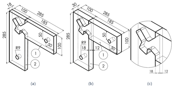
Fig. 1. (a) Through self-locking joint; (b) half lap self-locking joint (c); shaped tenon detail of the half lap joint, (measurements in mm). 1, Rail; 2, post
Methods of Loading and Testing
The load carrying capacity, stiffness, and strain fields of the self-locking furniture joints were investigated experimentally. The experimental results were used to verify FEA models. The properties of the joints mentioned above were estimated by FEA.
Load Carrying Capacity and the Stiffness of the Joints
The mechanical properties of the experimental joints were determined by compression (Fig. 2a) and tensile bending (Fig. 2b) tests. The experiments were carried out using a digital controlled machine (Shimadzu AG-IC 100KN, Kyoto, Japan) recording the force (F) with 0.01 N accuracy and the displacement (C) with an accuracy of 0.01 mm. The speed of loading was 5 mm/min. The compression and the tensile bending tests were carried out at Lahti University of Applied Sciences, Finland.
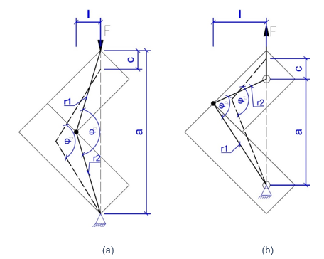
Fig. 2. (a) Compression bending test; (b) tensile bending test
The loading continued until the tested sample was broken. The recorded ultimate forces (N) were converted to the load carrying capacity values by Eq. 1,
![]()
The stiffness was calculated according to Eq. 2,
![]()
Compression bending was calculated as follows,
![]()
where c40 and c10 are the displacement caused by 40% and 10% loading, respectively.
Tensile bending test was calculated by Eq. 4,
![]()
where c40 and c10 are the displacement caused by 40% and 10% loading, respectively (Langová et al. 2011).
Strain Fields Measurement of the Self-locking Joints
The surface deformation field of joints was measured by a contactless system Aramis3D 12 M (GOM, GmbH, Braunschweig, Germany). The system uses digital image correlation (DIC) principles to obtain a full displacement field of the loaded surface and calculates the full strain field. The system consists of two CCD cameras with a resolution of 4096 x 3072 pixels, two 100 mm focal length lenses, and two artificial 24 W LED units (KSP0459; Schneider Optische Werke, GmbH, Bad Kreuznach, Germany). The natural surface of joints did not have the required contrast pattern; it was made by spraying a black pattern on a white background.
The area of interest (AOI) for the strain analysis covered the entire joint. To capture AOI with a maximal strain accuracy, the cameras were mounted on a slider 510 mm apart and calibrated at the measuring distance of 1240 mm. The aperture diaphragm of f/11 provided a large depth of field (74 mm) that sufficiently covered an accidental out of plane movement during loading. The Aramis 3D system was calibrated using 13 different images of a calibration object GOM/CP20/MV 250 x 200 mm2. The scale of capturing the projected surface was 13.21 pixels/mm.
The strain fields were calculated by a system from the partial derivatives of the displacement using Lagrange notation. Each displacement point was defined as a subset of 19 x 19 pixels, while 4 pixels overlapped the neighboring subset from each side. The distance of points/subsets was 15 pixels, and the density of correlated points was 0.75 points/mm2. The average strain accuracy of 0.000545 (or 545 micro-strains) was estimated from a noise of five images that were acquired before loading.
Finite Element Analysis (FEA) of the Self-locking Furniture Joints
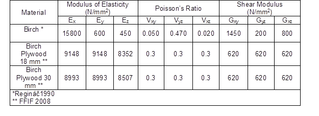
Nonlinear analyses of orthotropic materials, including large displacements, were carried out with the Solidworks software (Špinar Software, Brno, Czech Republic). Between all adjoining surfaces of the joints, non-penetration contacts were used. The elastic properties of materials are shown in Table 1. The major strain measured by the DIC method was compared with FEA-calculated strain as previously described (Sebera et al. 2013). The strain distribution patterns were visually compared.
Table 1. Elastic Properties of Materials
RESULTS AND DISCUSSION
Load Carrying Capacity and Stiffness
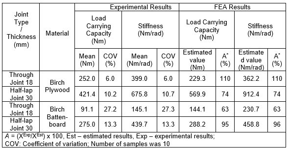
The average values of the load carrying capacity, stiffness of the self-locking joints, and coefficients of variation for the compression and the tensile bending tests are given in Tables 2 and 3, which include the experimental and the finite element analysis results. The FEA results are estimated with a certain accuracy (A; %).
All samples failed completely between 1 and 3 min. The samples gradually opened in the contact surfaces during loading before they were damaged. The samples did not open suddenly due to an absence of fasteners or glue. During compression bending of the through joint made of birch plywood, a failure occurred in the tenon neck. The same type of joint tested by tensile bending failed in the left upper area of the post. The through joint made from the birch battenboard cracked along the grain in the upper area of the post after the compression-bending test. The tensile bending in the through joint made of the birch battenboard caused two cracks along the grain. The cracks occurred in both the post (the upper area) and the rail (the lower part of the tenon). The half lap joint, made of the birch plywood loaded by the compression bending, was damaged in the neck of the tenon. A sizeable crack was caused by the tensile bending in the same joint on the top surface of the post. With regard to the half lap joint made of the birch battenboard tested by the compression bending two cases of failures occurred. In the first case, a crack occurred in the lower part of the tenon and in the neck of the tenon. In the second case, a sizeable crack appeared on the top of the post and in the lower part of the tenon. Tensile bending caused a crack in the lower part of the tenon in the half lap joint made of the battenboard.
Table 2. Mean Load Carrying Capacity and Stiffness of the Self-locking Furniture Joints with Coefficients of Variation and Estimated FEA Results under the Compression Bending
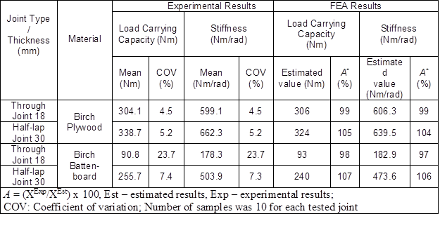
Table 3. Mean Load Carrying Capacity and Stiffness of the Self-locking Furniture Joints with Coefficients of Variation and Estimated FEA Results under the Tensile Bending
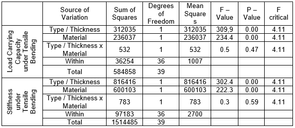
A two-way analysis of variance (ANOVA) general linear model was determined for the stiffness and the load carrying capacity data for the compression bending test (Table 4) and the tensile bending test (Table 5). The main factors (thickness and material) and the interaction factors that affect the mechanical properties of the self-locking furniture joints were analyzed. The compression bending results indicated that the effects of the main factors and the two-factor interaction on both the load carrying capacity and the stiffness of the self-locking joints were statistically significant at the 5% significance level. Under tensile bending, the effects of the main factors were statistically significant, while the effects of two-factor interaction were not statistically significant at the 5% significance level.
Table 4. Summary of the ANOVA Results for the Load Carrying Capacity and the Stiffness under the Compression Bending
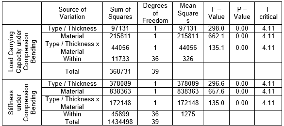
Table 5. Summary of the ANOVA Results for the Load Carrying Capacity and the Stiffness under the Tensile Bending
Duncan’s multiple range test at the 5% significance level was performed to determine the mean differences in the load carrying capacity as well as the stiffness of the self-locking joints under both the compression and the tensile bending. The groups with the same letter in Figs. 3 and 4 were not statistically significant.
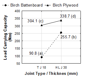
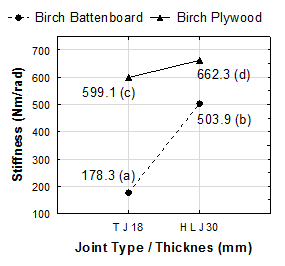
Fig. 3. Mean comparison of the load carrying capacity and the stiffness for the joint type / thickness and the materials under compression bending. T J, through joint; H L J, half lap joint
Figure 4 shows the mean comparison of the load carrying capacity and the stiffness of the self-locking joints under the tensile bending affected by both factors the joint type/thickness and the material. The load carrying capacity of the half lap joints was considerably higher than the load carrying capacity of the through joints. For the H L J made of birch battenboard, the load carrying capacity was about 201% higher than the load carrying capacity of the T J made of birch battenboard. The increase in the load carrying capacity from the T J made of the birch plywood to the H L J made of the birch plywood was 67%.
The load carrying capacity of the T J made of the birch battenboard was 63% lower than the load carrying capacity of the T J made of the birch plywood. The H L J made of the birch plywood reached a 53% higher load carrying capacity then the H L J made of the birch battenboard. The stiffness of the T J made of the birch battenboard was 67% lower than the stiffness of the H L J made of the birch battenboard. The increase of 69% was between the stiffness of the T J made of the birch plywood and the stiffness of the H L J made of the birch plywood in favor of the H L J. The T J made of the birch battenboard reached about a 63% lower stiffness than the T J made of the birch plywood.
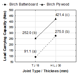
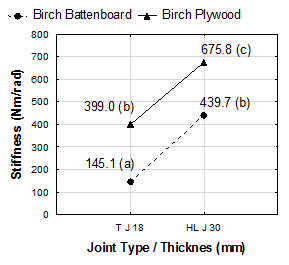
Fig. 4. Mean comparison of the load carrying capacity and the stiffness for the joint type/thickness and the materials under tensile bending. T J, through joint; H L J, half lap joint
The best value of the stiffness was exhibited by the H L J made of birch plywood. Compared with the H L J made of birch battenboard, the stiffness of the H L J made of birch plywood was 53% higher. There was no significant difference between the H L J made of birch battenboard and the T J made of birch plywood in the load carrying capacity or the stiffness.
Langová et al. (2013) found that the tensile bending load carrying capacity of the modified short joint made of 18 mm beech plywood was 362.7 Nm, which was 43% higher than the load carrying capacity of the T J made of the birch plywood.
Comparison of the Experimentally Ascertained Strain Fields with the Theoretical Strain Fields of the Self-locking Furniture Joints
Figures 5 through 12 show how similar the Aramis 3D and the Solidworks software calculated the strain fields on front surfaces of the joints. This analysis was an additional method for verifying the FEA models.
The analysis showed that the theoretical strain fields were very similar to the experimental strain fields, except in the case of the major strain comparison of the half lap joint made of the birch battenboard 30 mm thick under the tensile bending test (Fig. 12). In this case, the FEA model calculated some strain fields in the post that did not appear in the 3D Aramis strain fields calculation. Notably, the most loaded area (neck of the tenon) had almost the identical strain field.
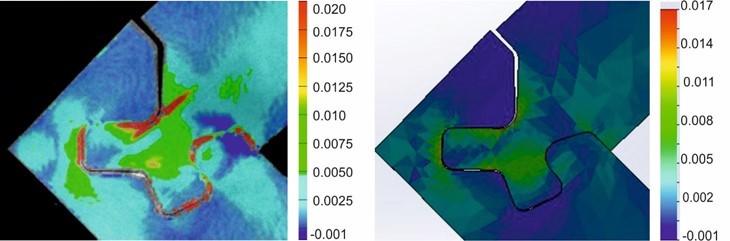
Fig. 5. The major strain comparison of the Through Joint made of the birch plywood 18 mm thick under the compression bending test at the force of 5.10 kN. The Aramis 3D experimental strain fields calculation is in the left panel, and the Solidworks theoretical strain fields calculation is the right panel.
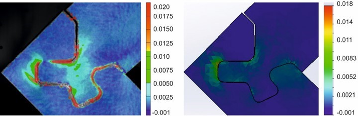
Fig. 6. The major strain comparison of the Through Joint made of the birch battenboard 18 mm thick under the compression bending test at the force of 1.55 kN. The Aramis 3D experimental strain fields calculation is in the left panel, and the Solidworks theoretical strain fields calculation is the right panel.
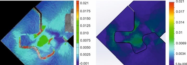
Fig. 7. The major strain comparison of the Half Lap Joint made of the birch plywood 30 mm thick under the compression bending test at the force of 5.40 kN. The Aramis 3D experimental strain fields calculation is in the left panel, and the Solidworks theoretical strain fields calculation is the right panel.
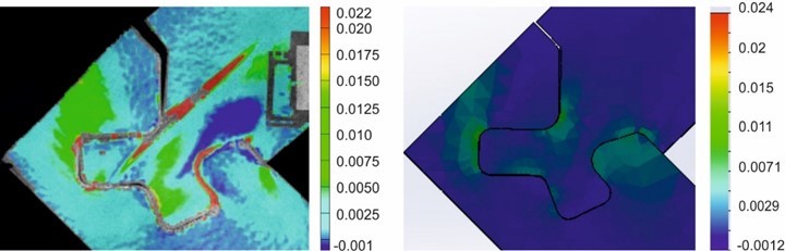
Fig. 8. The major strain comparison of the Half Lap Joint made of the birch battenboard 30 mm thick under the compression bending test at the force of 4.00 kN. The Aramis 3D experimental strain fields calculation is in the left panel, and the Solidworks theoretical strain fields calculation is the right panel.
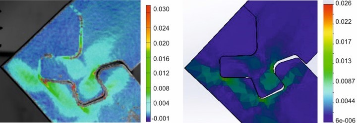
Fig. 9. The major strain comparison of the Through Joint made of the birch plywood 18 mm thick under the tensile bending test at the force of 1.75 kN. The Aramis 3D experimental strain fields calculation is in the left panel, and the Solidworks theoretical strain fields calculation is the right panel.
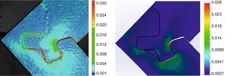
Fig. 10. The major strain comparison of the Through Joint made of the birch battenboard 18 mm thick under the tensile bending test at the force of 1.1 kN. The Aramis 3D experimental strain fields calculation is in the left panel, and the Solidworks theoretical strain fields calculation is the right panel.
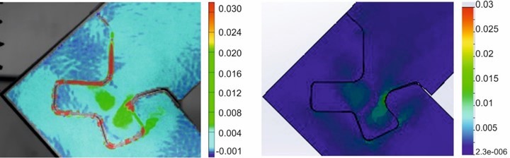
Fig. 11. Major strain comparison of the Half Lap Joint made of the birch plywood 30 mm thick under tensile bending test at the force of 4.35 kN. The Aramis 3D experimental strain fields calculation is in the left panel; the Solidworks theoretical strain fields calculation is the right panel.
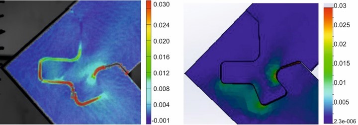
Fig. 12. The major strain comparison of the Half Lap Joint made of the birch battenboard 30 mm thick under the tensile bending test at the force of 2.20 kN. The Aramis 3D experimental strain fields calculation is in the left panel, and the Solidworks theoretical strain fields calculation is the right panel.
CONCLUSIONS
- Birch plywood was a much more appropriate material for the self-locking furniture joints than the birch battenboard, regardless of whether a joint material was 18 mm or 30 mm thick.
- In general, the half lap joints reached a higher load carrying capacity and a stiffness than the through joints.
- Reasonable results were obtain by FEA models. The results were verified in two ways. The first verification was based on experimental definition of the load carrying capacity and the stiffness. The second verification method was based on the experimental determination of strain fields. Thus, it was possible to estimate the mechanical properties of self-locking joints made of the birch plywood or the birch battenboard with different tenon shapes.
- The load carrying capacity, stiffness, and strain fields provided an adequate basis for verifying of theoretical FEA results of self-locking furniture joints.
ACKNOWLEDGMENTS
The authors are grateful for the financial support of Lahti University of Applied Sciences.
The authors are grateful for the financial support of the Ministry of Education of the Slovak Republic, project VEGA 1/0626/16, and the Slovak Research and Development Agency under the contract No. APVV-14-0506.
REFERENCES CITED
Bürdek, B. E., Gros, J., Krauter, M., and Sulzer, F. (1998). Digital Woodjoints, Edition dds, Stuttgart, Germany.
Derikvand, M., and Ebrahimi, G. (2013). “Finite element analysis of stress and strain distribution in mortise and loose tenon joints,” Journal of Forestry Research 25(3), 677-681. DOI: 10.10007/s11676-014-0507-5
Finnish Forest Industries Federation (FFIF) (2007). User Guide: Handbook of Finnish Plywood, UPM, Lahti, Finland.
Hajdarević, S., and Martinović, S. (2014). “Effect of tenon length on flexibility of mortise and tenon joint,” Procedia Engineering 69, 1877-7058. DOI: 10.1016/j.proeng.2014.03.042
ISO 13061-2 (2014). “Physical and mechanical properties of wood – Test methods for small clear wood specimens – Part 2: Determination of density for physical and mechanical tests,” International Organization for Standardization, Geneva, Switzerland.
Kasal, A., Eckelman, C. A., Haviarova, E., Erdil, Y. Z., and Yalçin, I. (2015). “Bending moment capacities of L-shaped mortise and tenon joints under compression and tension loadings,” BioResources 10(4), 7009-7020. DOI: 10.15376/biores.10.4.7009-7020
Kasal, A., Smardzewski, J., Kuşkun, T., and Erdil, Y. Z. (2016). “Numerical analyses of various sizes of mortise and tenon furniture joints,” BioResources 11(3), 6836-6853. DOI: 10.15376/biores.11.3.6836-6853
Kaygin, B., Yorur, H., and Uysal, B. (2016). “Simulating strength behaviors of corner joints of wood constructions by using finite element method,” Drvna Industrija 67(2), 133-140. DOI: 10.5552/drind.2016.1503
Langová, N., Joščák, P., and Gaff, M. (2011). Nábytkové Konštrukčné Spoje [Furniture Joints](Report number), Technická Univerztita vo Zvolene, Zvolen, Slovakia.
Langová, N., Joščák, P., and Grič, M. (2013). “Strength properties of self-locking furniture joints with shape adapted for the production by CNC technology,” Annals of Warsaw University of Life Sciences 83, 1898-5912.
Nicholls, T., and Crisan, R. (2002). “Study of the stress-strain state in corner joints and box-type furniture using Finite Element Analysis (FEA),” Holz als Roh- und Werkstoff 60, 66-71. DOI: 10.1007/S00107-001-0262-0
Regináč, L. (1990). Náuka o dreve II [Science of Wood II], VŠLD, Zvolen, Slovakia.
STN 91 0000:2009-08 (2009). “Terminology in furniture industry. Basic terms,” Slovak Technical Standards, Bratislava, Slovakia.
Sebera, V., Muszyński, L., Tippner, J., Noyel, M., Pisaneschi, T., and Sundberg, B. (2013). “FE analysis of CLT panel subjected to torsion and verified by DIC,” Materials and Structure 48(1), 451-459. DOI: 10.1617/s11527-013-0195-1
Smardzewski, J. (1998). “Numerical analysis of furniture construction,” Wood Science and Technology 32, 273-286. DOI: 10.1007/BF00702895
Sumiyoshi, T., and Matsui, G. (1991). Wood Joints in Classical Japanese Architecture, Kajima Institute Publishing, Tokyo, Japan.
Wang, Y., and Lee, S. H. (2014). “Design and analysis on interference fit in the hardwood dowel-glued joint by finite element method,” Procedia Engineering 79, 1877-7058. DOI: 10.1006/j.proeng.2014.06.326
Article submitted: February 14, 2017; Peer review completed: May 11, 2017; Revised version received and accepted: June 10, 2017; Published: June 15, 2017.
DOI: 10.15376/biores.12.3.5525-5538