
Abstract
A new sandwich composite structure was prepared that utilizes classic wood-based composites as the core and face materials. Particleboards were used as faces, which covered a plywood-made iso-grid core. A new type of core-face fixation was suggested and assessed. The sandwich panels can be regarded as lightweight, as their density was below 400 kg/m3. Digital image correlation (DIC) was used to determine Poisson’s ratios and obtain additional insight into the deformation behavior of the sandwich panel. DIC was also employed to assess the core-face bonding, which was based on imprinted grooves on one side of the particleboard face. The results include strength in edgewise and flatwise compression and flexural properties. The latter were determined through three-point bending tests. Comparable strength properties were found relative to the literature, which means that this new type of sandwich panel demonstrates a competitive property profile. It was concluded that the developed sandwich panel is versatile, and the hollow spaces in the core can be filled with insulation materials such as fibers or foams. Surfaces can also be covered with some overlay, delivering improved bending performance.
Download PDF
Full Article
Novel Sandwich Panel with Interlocking Plywood Kagome Lattice Core and Grooved Particleboard Facings
Petr Klímek,* Rupert Wimmer, Martin Brabec, and Václav Sebera
A new sandwich composite structure was prepared that utilizes classic wood-based composites as the core and face materials. Particleboards were used as faces, which covered a plywood-made iso-grid core. A new type of core-face fixation was suggested and assessed. The sandwich panels can be regarded as lightweight, as their density was below 400 kg/m3. Digital image correlation (DIC) was used to determine Poisson’s ratios and obtain additional insight into the deformation behavior of the sandwich panel. DIC was also employed to assess the core-face bonding, which was based on imprinted grooves on one side of the particleboard face. The results include strength in edgewise and flatwise compression and flexural properties. The latter were determined through three-point bending tests. Comparable strength properties were found relative to the literature, which means that this new type of sandwich panel demonstrates a competitive property profile. It was concluded that the developed sandwich panel is versatile, and the hollow spaces in the core can be filled with insulation materials such as fibers or foams. Surfaces can also be covered with some overlay, delivering improved bending performance.
Keywords: Wood-based panel; Sandwich structure; Mechanical testing; Digital image correlation; DIC; Imprinted density pattern
Contact information: Faculty of Forestry and Wood Technology, Mendel University in Brno, Zemědělská 3, 613 00 Brno, Czech Republic; *Corresponding author: xklimek@node.mendelu.cz
INTRODUCTION
Sandwich composite materials that display high strength to low density have been favored for structural and aesthetic applications, e.g., in aerospace, marine, or automotive industries (Davies 2001; Vasiliev et al. 2001; Fan et al. 2007). High stiffness-to-density ratios are obtained by designing suitable core materials, which can be made of foams (Shalbafan 2013), low-density materials such as balsa wood (Bekisli and Grenestedt 2004; Kepler 2011), cork (Král et al. 2014), an iso-grid structure (Vasiliev et al. 2001; Fan et al. 2007; Zhang et al. 2008; Li et al. 2014), or paper-based corrugated structures (Hunt and Gunderson 1988; Hunt et al. 2004; Labans and Kaliniš 2011). To obtain a sandwich composite, the core is covered by lamellar top layers made of various materials. The range of possible core structures allows versatile configurations and specifications of the iso-grid core. Interlocking grids have been used in the development of various products (Vasiliev et al. 2001; Fan et al. 2007; Tao et al. 2011). Iso-grid shapes, which have been made with metal and laminate materials (Fan et al. 2007; Li et al. 2014), might also be possible using strips prepared from plywood. Plywood as a corrugated core material has been utilized in sandwich panels (Bhattacharyya et al. 2011; Labans and Kaliniš 2011). Beside stiffness and strength of the material, Poisson’s ratios of the material are also important for the assessment of the deformation behavior.
In general, sandwich composite materials require sound numerical models to fully understand the structural and mechanical behavior (Mackerle 2005; Wilczyński and Kociszewski 2010; Labans and Kaliniš 2011; Kanou et al. 2013). Research on robust material models may include non-contact optical techniques such as digital image correlation (DIC), which has been used to analyze wood-based composites on various scales (Zink et al. 1995; Sutton et al. 2009; Hussain et al. 2011; Sebera et al. 2013).
In this research, a new sandwich composite structure is proposed, utilizing classic wood-based composites as core and face materials. As core-face bonding is crucial in manufacturing (Davies 2001), a new type of core-face fixation is suggested using imprinted grooves in the inner sides of the face material. The following research issues are addressed: (1) development of a lightweight sandwich composite having an interlocking iso-grid plywood core, covered by grooved particleboard faces; (2) analysis of bending and compressive performance, (3) qualitative analysis of bondline failures, and (4) determination of Poisson’s ratios using DIC.
EXPERIMENTAL
The newly introduced sandwich composite is composed of two components: (1) particleboard face layers that are groove-imprinted on one side, and (2) a 3-layer birch plywood cut in straight strips and intersected to form the iso-grid core. Single-layer particleboards were produced on a laboratory scale with in-situ imprinting of self-designed hexagonal patterns, under the conditions listed in Table 1. The grooves imprinted on the inner sides of the particleboard faces provided exact positioning of the plywood strips, which improved the overall core-face bonding (Fig. 1).
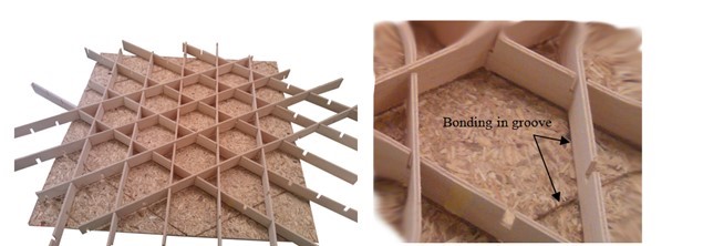
Fig. 1. Particleboard faces with imprinted grooves for iso-grid core positioning and fixation
A single-layer particleboard with an imprinted hexagonal pattern was produced in the laboratory, under the conditions listed in Table 1. The particles were obtained from a local particleboard manufacturer; the average particle size was 1.7 mm in width and 7.5 mm in length. Gluing for the particleboards was done with the urea-formaldehyde resin Prefere 4170 (Dynea™, Lillestrom, Norway) and the hardener Kronoadd HL 100 (Dukol Ostrava s.r.o, Ostrava, Czech Republic). Particles were resinated in a laboratory rotating drum for 10 min, with hardener and distilled water subsequently added. The moisture content was adjusted to 11%. The particle furnish was manually pre-pressed in a rectangular wooden frame 600 × 600 mm in size prior to insertion in the hot-press. Metal distance bars 5 mm in thickness were used on both sides of the particle mat. The stainless steel iso-grid pattern was positioned on top of the pre-pressed particle mat (Fig. 2). Particleboards were pressed for 50 s at 190 °C, at a specific press-pressure of 3.2 MPa. After pressing, the stainless steel iso-grid pattern was removed and the boards were conditioned for two weeks at 65% relative humidity and 24 °C. Finally, the particleboards were formatted to 500 × 500 mm.
Table 1. Parameters for Laboratory-produced Single-layer Particleboards
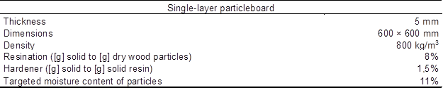
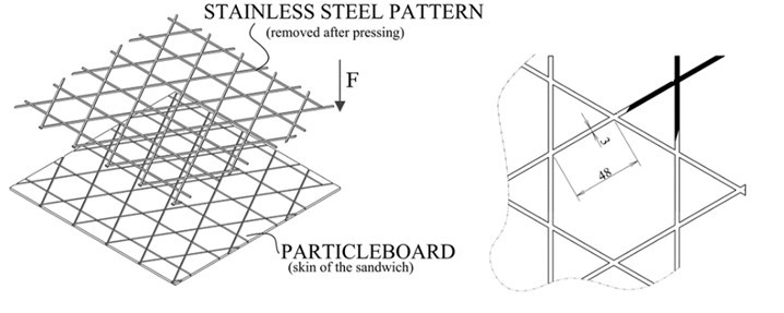
Fig. 2. Particleboard face with inserted stainless steel pattern for imprinting (left); stainless-steel iso-grid pattern (right)
Strips 35 mm in width were cut from 3-mm three-layer birch plywood obtained from a local manufacturer. Strips were pre-assembled without adhesive and glued into the imprinted groove pattern (Fig. 1) by using PVAc adhesive Soudal 67A (INVA Building Materials s.r.o, Praha, Czech Republic), which was equally applied to all the grooves prior to assembling. No adhesive was applied to hold the plywood pieces to each other. The sandwich panel was pressed at a specific pressure of 0.7 MPa for 45 min, followed by conditioning for 24 h at 24 °C and 65% relative humidity to ensure proper curing of the adhesive.
Samples were cut from the particleboard as shown in Fig. 3. Mechanical properties were measured according to ASTM C365-11 (2011), ASTM C393-06 (2006), and ASTM C297 (2009) standards. Tests were performed on a ZWICK Z050/TH 3A (Zwick Roell AG, Ulm, Germany) universal testing machine.
Edgewise Compression Test
The edgewise compression test followed ASTM C364-07 (2012), which was used to measure the facing compressive panel strength. A loading rate of 2 mm/min was applied to both tested specimens that were cut from the sandwich panel. Because of the symmetrical shape of the core, only one edgewise loading direction was tested. Table 2 lists details of all of the tested samples.
Flatwise Compression Test
The compressive properties of the panel were measured according to ASTM C365-11 (2011) in a flatwise direction. The panel strength and modulus of elasticity (MOE) were assessed.
The loading rate was 2 mm/min. Specimens were cut from the panels in such a way that they covered the entire hexagonal iso-grid units of the core (Table 2).
Bending Tests
Three-point bending tests followed ASTM C393-06 (2006) to obtain shear stresses in the core as well as in the faces. The sandwich panel width allowed the inclusion of a complete iso-shape core unit (Fig. 3). The span between the supports (l) was 410 mm, and the sandwich panel width (b) was 112 mm. The face layer thickness was 5 mm, and the total panel thickness was 38 mm (Table 2). The loading rate was set to 6 mm/min to reach failure within 90 s.
Shear stress τ (Eq. 1) was determined with a three-point bending test, with P being the load (N), d the sandwich thickness (mm), c the core thickness (mm), and b the sandwich width (mm).
![]() (1)
(1)
Flexural facing strength (σ) was determined according to Eq. 2, with t being the face thickness (mm), L the span length (mm), d the sandwich thickness (mm), c the core thickness (mm), and b the sandwich width (mm).
![]() (2)
(2)
Flatwise Tension Test
The bonding strength between faces and the core was determined with the flatwise tensile test following ASTM C297 (2009). The samples were prepared in such a way that a symmetric triangular shape of the core was covered (T1-T3, Fig. 3). Samples 50 × 50 mm in size were glued with the hot-melt adhesive Siga® N-40 (Siga a.s., Zlín, Czech Republic) onto metal blocks and then tested on a ZWICK Z050/TH 3A (Zwick Roell AG, Ulm, Germany).
The loading rate was 1 mm/min, to achieve failure within 60 to 90 s. Three samples per sandwich panel were tested.
Table 2. Description of Specimens Used for Testing
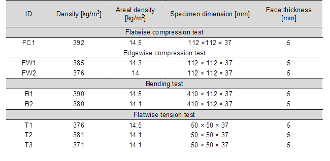

Fig. 3. Samples location on the sandwich panel (FC: sample for flatwise compression test,
FW1-FW2: samples for edgewise compression test, T1-T3: samples for flatwise tension test,
B1-B2: samples for bending test)
Digital Image Correlation Analysis
While running the test on the ZWICK Z050/TH 3A (Zwick Roell AG, Ulm, Germany), a stereoscopic camera system was simultaneously installed to acquire images for 3D digital image correlation (3D-DIC) analysis. The goal was to characterize the material’s deformation behavior. The stereoscopic system consisted of two CCD video cameras (AVT Stingray Copper F-504B, Allied Vision Technologies, Osnabrück, Germany, cell size of 3.45 μm) with a resolution of 2452 × 2056 px2. The lenses (Pentax C2514-M, Pentax Precision Co., Ltd., Tokyo, Japan) had a focal length of 25 mm, and all captured images were grey-scale with 256 intensity levels. Observed sample side was covered with stochastic and high-contrast speckle pattern. Firstly the white color was applied onto the surface and after curing the random black spray speckle pattern was manually sprayed. The two-component stochastic and contrast pattern is proposed to enhance image correlation. The surfaces were illuminated by two diffuse lights SobrietyCube 360 (Sobriety s.r.o., Kuřim, Czech Republic) with LED sensors (Luminus Phlatlight CSM-360, 90W, Luminus Devices Inc., Billerica-MA, USA). The images were used to calculate displacement and strain fields using a DIC algorithm implemented in software VIC-3D (Correlated Solutions Inc., Columbia-SC, USA). Poisson’s ratios (PR) were calculated from the mean values from the whole area of interest (AOI) according to Eq. 3,
ʋxy = ɛx/ɛy (3)
where ʋxy is PR, ɛx is strain in the x direction, and ɛy is strain in the y direction. Each compressive test of the panel’s main plane resulted in stress-strain diagrams. These diagrams were used to identify elastic regions of deformation that were further used in the DIC calculation. The stereoscopic system was focused on cross-sectional planes of the samples to obtain strain data for the calculation of Poisson’s ratios (PR). PRs were examined in the elastic region of the deformation (within 50 to 60 s of testing) and at three main planes. In the case of strain field inconsistency (ʋyx; ʋxy) resulting from the strip structure, an alternative approach using a virtual extensometer was chosen as an evaluation tool of VIC-3D (Correlated Solutions Inc., Columbia-SC, USA) software. This provided change of dimension data between two points located on the surface layers of the board (Fig. 4).
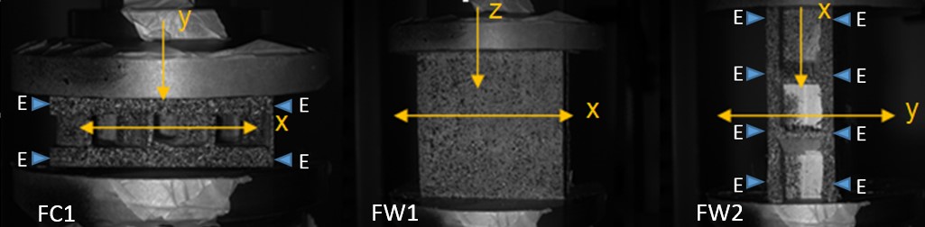
Fig. 4. The examined planes for obtaining Poisson´s ratio using DIC with applied pattern (left- ʋyx; middle- ʋzx; right- ʋxy); Es are the positions of virtual extensometers used for obtaining ʋyx and ʋxy
RESULTS AND DISCUSSION
Mechanical Behavior of Compression
In the edgewise compression tests (Fig 5), the MOE was derived from the elastic region of the stress-strain curve, and equaled 201 MPa for the FW1 and 220 MPa for the FW2. The compression strength in an edgewise direction was 14.5 MPa. In addition, the obtained data were similar to those reported for spaceboard panel, which also has a hollowed core (Hunt and Gunderson 1988).
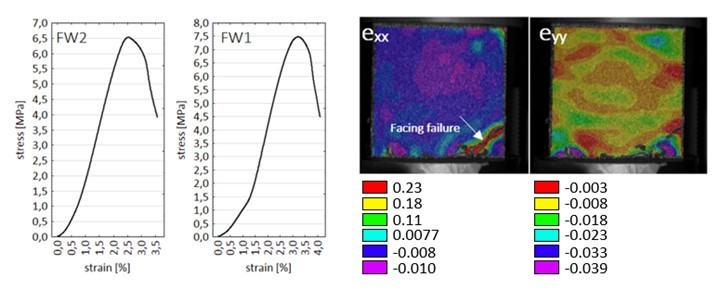
Fig. 5. Compression stress vs. strain diagrams for the novel wood-based sandwich composite and strain situation on the facing in time of failure
In the flatwise direction, a MOE of 112 MPa (FC1, Fig. 6) was determined, which was lower than the MOE found in the edgewise direction. The same sample had a flatwise compressive strength of 2.64 MPa. Although core-grid shapes have been used by others (e.g., Fan et al. 2007; Tao et al. 2011), a direct comparison was not possible because different failure mechanisms are in place. Additionally, other materials (e.g., metal, carbon fiber reinforcement) were used. The compressive properties of the new sandwich panel are comparable to honeycomb materials (Bhattacharyya et al. 2011), including polyimide honeycomb structures, as some with lower density reached a comparable flatwise compressive strength of 3 MPa (Hexcel Composites 1999).
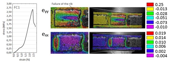
Fig. 6. Compression stress vs. strain for the novel wood-based sandwich composite and strain situation on the cross section of the sample in time of failure
The grid bonding in the impressed grooves is seen as a novel feature of the new sandwich structure. Using digital image correlation, a deformation evaluation was completed (Fig. 7). As is visible, the regions where the ribs were present showed lower deformation than the rest of the panel. Especially, vertical deformations (eyy) were significantly lower in area of the ribs. The eyy of area with ribs was mostly -0.0005 (-), while in the center of the sample eyy ranged from -0.0018 to -0.0210 (-).
Table 3. Flatwise and Edgewise Compression Test
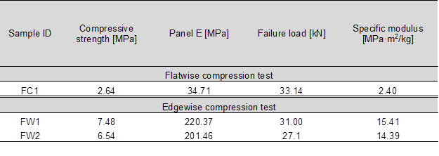
FC1- flatwise compressive strength sample; N=1; FW1, FW2- edgewise compressive strength samples; N=2
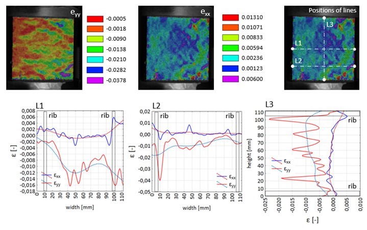
Fig. 7. Deformations (ε) [-] of the facing in x and y direction in selected regions evaluated by DIC. FW2 sample was evaluated in loading of 7 MPa. L1; L2 and L3 are inspection lines along which deformations were listed in graphs
Flexural Properties
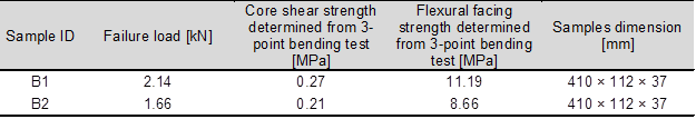
Samples B1 and B2 cut from the sandwich panel were tested to determine the loads at failure, which were 2.14 kN and 1.66 kN, respectively (Table 4, Fig. 9). The core shear strength values of B1 and B2 were 0.27 MPa and 0.21 MPa, respectively. Flexural facing strength was measured at 11.19 and 8.66 MPa. Samples failed at the outer side of the lower facing. The flexural facing strength was lower than the data reported by Li et al. (2014). Furthermore deformation evaluation (Fig. 8) by DIC showed that facings are distributing the most of the exx deformations during the bending. As is common, the top facing was distributing positive strain (+exx), reaching a maximal value of 0.0123 (-), while the bottom facing was distributing negative strain (-exx), which was -0.014 (-). The stress-strain curve is shown in Fig. 9. For future research, consideration of the application of various surface materials to enhance bending properties is recommended, e.g., veneer overlays (Kawasaki et al. 1999; Král et al. 2013; Král et al. 2014) or fiber glass reinforcement (Li et al. 2014).
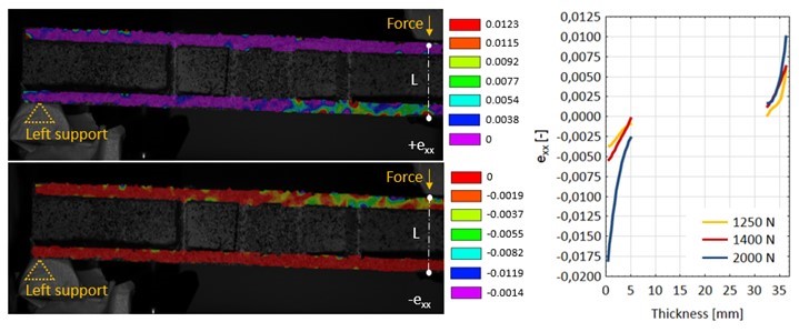
Fig. 8. Positive (+exx) and negative (-exx) strain distribution in the facings measured by DIC; figures on left side are captured when 2000 N force is applied, L – line where strain distribution was listed in graph
Table 4. Flexural Properties of the Sandwich Panel
B1, B2- bending samples used for determination of the bending properties; N=2
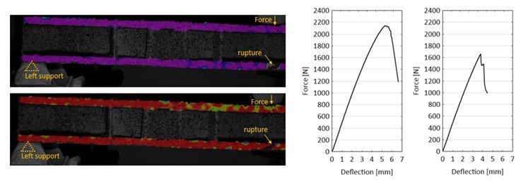
Fig. 9. The loading-deformation curve with respect to applied force and deflection of the sample
Flatwise Tensile Properties
The flatwise tensile test delivered an average tensile strength of 0.5 MPa (Table 4). The tested samples revealed that the weakest point of the sandwich construction is the particleboard facing, as particles tended to debond from the remaining layer (Fig. 10). Interestingly, the flatwise tensile strength of the sandwich panel was similar to the flatwise tensile strength of common particleboards, with strength values ranging from 0.4 to 0.8 MPa (Wimmer and Weigl 2007; Riegler et al. 2013).
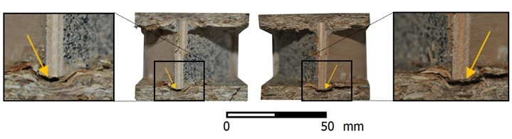
Fig. 10. Failure of the grooved bonding after flatwise tension testing (failure marked with yellow arrows)
Table 5. Tensile Strength Properties of the Sandwich Panel; T1-T3: tensile strength samples

DIC Evaluation and Poisson’s Ratio Determination
The linear section of the stress-strain curve was evaluated every second during loading. Four Poisson’s ratios were computed every second during testing. Poisson’s ratios were statistically evaluated (Table 6), and they were determined to be 0.172 in the ʋzx direction, 0.037 in the ʋxy direction, and 0.036 in the ʋyx direction. The Poisson’s ratios are displayed as a box-whisker plot in Fig. 11. The determination of the Poisson’s ratios is important especially for finite element modeling. Poisson’s ratios are critical in finite element modeling (Mackerle 2005; Labans and Kaliniš 2011; Sebera et al. 2013; Sebera et al. 2014).
Table 6. Poisson’s Ratios of the Sandwich Panel

ʋ- Poisson’s ratio; zx, xy, yx- evaluated strain directions
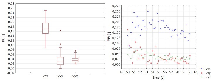
Fig. 11. The variability of the Poisson’s ratios in the 50 to 60 sec of the load-deformation curve
CONCLUSIONS
- A novel sandwich panel was successfully assembled that included an iso-grid interlocking core, which was characterized by a flatwise compressive strength of 2.64 MPa, an edgewise compressive strength of 6.4 MPa, a sandwich facing strength of 10 MPa, and a core shear strength of 0.21 MPa. In addition, the panel was lightweight, having a density of 392 kg/m3, which compared well with other published findings. The new panel can be defined as lightweight because the density remains below 400 kg/m3
- During mechanical testing, the panel failed in the iso-grid core during flatwise compression, and in the facings when the edgewise compression test was done. It is assumed that the novel grooved bonding into the facings may provide better bonding, as displacement was lower in the area of the groove.
- DIC was successfully used to evaluate the Poisson’s ratios for all directions. The ʋzx was 0.172, the ʋxy was 0.037, and ʋyx was 0.036.
- The sandwich panel is versatile, in that the empty core spaces could be filled with insulation materials such as fibers or foams, which would provide additional insulation capacity. Surfaces could also be equipped with additional overlays, which would deliver better bending performance.
- Regarding direct application, the grooved surface of the particleboard facing may be produced using common industrial press with a one-side shaped platen.
ACKNOWLEDGMENTS
This research was supported the Internal Grant Agency (IGA) of the Faculty of Forestry and Wood Technology, Mendel University in Brno, Project: LDF_VP_2015007.
REFERENCES CITED
ASTM C365-11 (2011). “Standard test method for flatwise compressive properties of sandwich cores,” ASTM International, West Conshohocken, PA.
ASTM C393-06 (2006). “Standard test method for core shear properties of sandwich constructions by beam flexure,” ASTM International, West Conshohocken, PA.
ASTM C364-07 (2012). “Standard test method for edgewise compressive strength of sandwich constructions,” ASTM International, West Conshohocken, PA.
ASTM C297 (2009). “Standard test method for flatwise tensile strength of sandwich constructions,” ASTM International, West Conshohocken, PA.
Bekisli, B., and Grenestedt, J. L. (2004). “Experimental evaluation of a balsa sandwich core with improved shear properties,” Composites Science and Technology 64(5), 667-674. DOI:10.1016/S0266-3538(03)00294-X
Bhattacharyya, D., Kavermann, S., Penneru, P., and Rao, S. (2011). “Veneer-based lightweight sandwich panel for high-end interior applications: Manufacturing, evaluation and cost analysis,” Joint International Symposium on Wood Composites and Veneer Processing and Products, Washington State University, Pullman, WA, pp. 1-11.
Davies, J. M. (ed.) (2001). Lighweight Sandwich Constructions, Blackwell Science Ltd, Osford, United Kingdoms.
DOI:10.1016/j.compositesb.2012.04.052
Fan, H. L., Meng, F. H., and Yang, W. (2007). “Sandwich panels with kagome lattice cores reinforced by carbon fibers,” Composite Structures 81(4), 533-539. DOI: 10.1016/j.compstruct.2006.09.011
Hexcel Composites (1999). “A comprehensive guide to standard Hexcel honeycomb materials, configurations, and mechanical properties,” Industriestrasse 1, A-4061 Pasching, Austria. Available at: http://www.hexcel.com/Resources/DataSheets/Brochure-Data-Sheets/Honeycomb_Attributes_and_Properties.pdf
Hunt, J. F., and Gunderson, D. E. (1988). “DPL spaceboard development,” TAPPI Proceeding of the 1988 Corrugated Containers Conference, Orlando, FL, TAPPI Press, pp. 11-17.
Hunt, J. F., Harper, D. P., and Friedrich, K. A. (2004). “Three-dimensional engineered fiberboard: Opportunities for the use of low valued timber and recycled material,” 38th International Wood Composites Symposium, Washington State University, Pullman, WA, pp. 207-216.
Hussain, F., Nairn, J., and Muszyński, L. (2011). “An experimental method for measurement of strain distribution between wood the flour particles and polymer matrix on micro-mechanical level,” Materials Science and Engineering A 528(18), 6072–6078. DOI: 10.1016/j.msea.2011.04.056
Kanou, H., Nabavi, S. M., and Jam, J. E. (2013). “Numerical modeling of stresses and buckling loads of isogrid lattice composite structure cylinders,” International Journal of Engineering, Science and Technology 5(1), 42-54. DOI: 10.4314/ijest.v5i1.4
Kawasaki, T., Min, Z., and Shuichi, K. (1999). “Sandwich panel of veneer-overlaid low-density fiberboard,” Journal of Wood Science 45(4), 291-298.
Kepler, J. A. (2011). “Simple stiffness tailoring of balsa sandwich core material,” Composites Science and Technology 71(1), 46-51. DOI: 10.1016/j.compscitech.2010.10.002
Král, P., Hrázský, J., Hrapková, L., and Hamšík, P. (2013). “Shape stability of particleboards covered with decorative veneers,” Drvna Industrija 64(3), 201-220. DOI: 10.5552/drind.2013.1234
Král, P., Klímek, P., Mishra, P. K., Rademacher, P., and Wimmer, R. (2014). “Preparation and characterization of cork layered composite plywood boards,” BioResources 9(2), 1977-1985. DOI: 10.15376/biores.9.2.1977-1985
Labans, E., and Kaliniš, K. (2011). “Numerical versus experimental investigation of plywood sandwich panels with corrugated core,” 3rd International Conference Civil Engineering´11 Proceedings II Materials and Structures, L. Malinovska and Z. Daiga (eds.), Latvia University of Agriculture, Jelgava.
Li, J., Hunt, J. F., Giong, S., and Cai, Z. (2014). “High strength wood-based sandwich panels reinforced with fiberglass and foam,” BioResources 1(2), 1898-1913. DOI: 10.15376/biores.1.2.1898-1913
Mackerle, J. (2005). “Finite element analyses in wood research: A bibliography,” Wood Science and Technology 39(7), 579-600. DOI: 10.1007/s00226-005-0026-9
Riegler, M., Spangl, B., Weigl, M., Wimmer, R., and Müller, U. (2013). “Simulation of a real-time process adaptation in the manufacture of high-density fibreboards using multivariate regression analysis and feedforward control,” Wood Science and Technology 47(6), 1243-1259. DOI: 10.1007/s00226-013-0571-6
Sebera, V., Muszyński, L., Tippner, J., Noyel, M., Pisaneschi, T., and Sundberg, B. (2013). “FE analysis of CLT panel subjected to torsion and verified by DIC,” Materials and Structures 48(1-2), 451-459. DOI: 10.1617/s11527-013-0195-1
Sebera, V., Tippner, J., Šimek, M., Šrajer, J., Děcký, D., and Klímová, H. (2014). “Poisson’s ratio of the MDF in respect to vertical density profile,” European Journal of Wood and Wood Products 72(3), 407-410. DOI: 10.1007/s00107-014-0780-1
Shalbafan, A. (2013). Investigation of Foam Materials to be Used in Lightweight Wood-Based Composites, Ph.D. dissertation, University of Hamburg, Hamburg, Germany.
Sutton, M. A., Orteu, J. J., and Schreier, H. W. (2009). Digital Image Correlation for Shape and Deformation Measurements: Basic Concepts, Theory and Applications, Springer Verlag, Heidelberg.
Tao, H. F., Fang, Z. D., and Yang, W. (2011). “Mechanics of advanced fiber reinforced lattice composites,” Acta Mechanica Sinica 26(6), 825-835. DOI: 10.1007/s10409-010-0390-z
Vasiliev, V. V., Barynin, V., and Rasin, F. (2001). “Anisogrid lattice structures – Survey of development and application,” Composite Structures 54(2-3), 361-370. DOI: 10.1016/S0263-8223(01)00111-8
Wilczyński, A., and Kociszewski, M. (2010). “Elastic properties of the layers of three-layer particleboards,” European Journal of Wood and Wood Products 70(1-3), 357-359. DOI: 10.1007/s00107-010-0497-8
Wimmer, R., and Weigl, M. (2007). “A multi-parameter approach to characterize wood quality for particle boards,” All Division 5 World Conference, Oct. 29-Nov. 2, Taipei, Taiwan.
Zhang, Y. H., Qiu, X. M., and Fang, D. N. (2008). “Mechanical properties of two novel planar lattice structures,” International Journal of Solids and Structures 45(13), 3751-3768. DOI: 10.1016/j.ijsolstr.2007.10.005
Zink, A. G., Davidson, R. W., and Hanna, R. B. (1995). “Strain measurement in wood using a digital image correlation technique,” Wood and Fiber Science 27(4), 346-359.
Article submitted: June 13, 2015; Peer review completed: August 31, 2015; Revised version received and accepted: October 20, 2015; Published: November 12, 2015.
DOI: 10.15376/biores.11.1.195-208