
Abstract
The crises in global energy and environmental degradation, combined with developing consumer demands have stimulated researchers’ interest in inexpensive, environmentally friendly functional materials. Based on a projected annual production of palm oil in Malaysia of over 15.4 million metric tons by 2020, it is estimated that about 46.6 tons of lignocellulosic wastes will be generated. Transforming these wastes into wealth could be integrated into a global paradigm shift towards sustainable development. Carbon-based nanomaterials including graphene, graphene oxide, carbon nanotubes, epoxy nanocomposites, porous carbon nanoparticles, and nanoactivated carbons-filled-epoxy nanocomposites have been produced from these by-product materials using methods such as vapour deposition, pyrolysis, hydrolysis, chemical composition, high energy ball milling, and solution casting. This review attempts to present the current developments on renewable carbon nanomaterials derived from oil palm-based precursors with some insights given on their potential applications as energy storage materials.
Download PDF
Full Article
Potential Valorization of By-product Materials from Oil Palm: A review of Alternative and Sustainable Carbon Sources for Carbon-based Nanomaterials Synthesis
Salisu Nasir,a,b,c,* Mohd Zobir Hussein,a,* Zulkarnain Zainal,c Nor Azah Yusof,c Syazwan Afif Mohd Zobir, d and Ibrahim Mustapha Alibe a
The crises in global energy and environmental degradation, combined with developing consumer demands have stimulated researchers’ interest in inexpensive, environmentally friendly functional materials. Based on a projected annual production of palm oil in Malaysia of over 15.4 million metric tons by 2020, it is estimated that about 46.6 tons of lignocellulosic wastes will be generated. Transforming these wastes into wealth could be integrated into a global paradigm shift towards sustainable development. Carbon-based nanomaterials including graphene, graphene oxide, carbon nanotubes, epoxy nanocomposites, porous carbon nanoparticles, and nanoactivated carbons-filled-epoxy nanocomposites have been produced from these by-product materials using methods such as vapour deposition, pyrolysis, hydrolysis, chemical composition, high energy ball milling, and solution casting. This review attempts to present the current developments on renewable carbon nanomaterials derived from oil palm-based precursors with some insights given on their potential applications as energy storage materials.
Keywords: Oil palm; Oil palm by-products; Environmental issues; Sustainable carbon sources; Carbon nanomaterials; Production; Nanoscience; Nanotechnology
Contact information: a: Materials Synthesis and Characterization Laboratory (MSCL), Institute of Advanced Technology (ITMA), Universiti Putra Malaysia, 43400 Serdang, Selangor, Malaysia; b:Department of Chemistry, Faculty of Science, Federal University Dutse, 7156 Dutse, Jigawa State, Nigeria; c: Department of Chemistry, Faculty of Science, Universiti Putra Malaysia, 43400 Serdang, Selangor, Malaysia; d: Materials Processing and Technology Laboratory (MPTL), Institute of Advanced Technology (ITMA), Universiti Putra Malaysia, 43400 Serdang, Selangor, Malaysia;
* Corresponding authors: salisunasirbbr@gmail.com; mzobir@upm.edu.my
INTRODUCTION
The Oil Palm (Elaeis guineensis): Brief History, Origin, and Use
The evolution of bioresource technology is crucial in this contemporary world. This is due to the waning popularity of fossil-based technology, which can be attributed to the severe declining of fossil fuel reserves and their adverse environmental effects. Secondly, lignocellulosic and other biomass-related materials have garnered attention as excellent renewable assets for the fabrication of chemicals, nanocellulose, carbon nanomaterials, and fuels. This biomass material consists of a complex biomatrix, encompassing various polysaccharides, phenolic polymers, and proteins in their structure. As an alternative approach to using fossil fuels, it is good news that carbon-based nanomaterials can be prepared directly from renewable natural materials, such as oil palm-based precursors.
With Malaysia as an indicator, the story of the oil palm industry is generally considered a sensational one. It should be noted that Elaeis guineensis (oil palm) is the second foremost agricultural crop grown in the country, accounting for 34.6% of the total crops grown, which is just behind rubber (39.7%). Rice (12.7%), cocoa (6.8%), and coconut (6.3%) are some of the other crops grown in Malaysia (Ong et al. 2011).
In the last couple of decades, the cultivation of oil palm has witnessed remarkable and sustained growth, and it is believed to be among the fastest expanding equatorial crops in the world. According to the Food and Agricultural Organization, the worldwide coverage of E. guineensis farming has significantly increased from 3.6 million ha in 1961 to 13.2 million ha in 2006 (FAO 2007).
The term Elaeis guineensis is a scientific name given to the common species of oil palm that was globally accepted as indigenous to/originated from Africa (Corley and Tinker 2003). Other species such as the American oil palm (Elaeis oleifera), and other indistinctly linked palm (Attalea maripa), are also used to produce palm oil. However, E. guineensis is the most prominently known contributor for the majority of palm oil produced and consumed in human history (FAO 2007). Based on the viability of this species, it is generally believed that the crop could be used to take care of the rising global needs for vegetable oils, which is forecasted to be near 240 million tons by 2050 (Barcelos et al. 2015). As mentioned earlier, the genetic origin of this plant has indubitably been linked to both West and South Africa. According to a report as compiled/contained in the Cambridge World History of Food, it was established that the initial use of oil palms by the West African coastal dwellers occurred over 5000 years ago. This assertion was prudently supported by the archaeological findings (in the late 1800s) of a palm oil jar in a tomb in Abydos, Egypt that dated back to approximately 3000 BC (Kiple and Ornelas 2000). It has been theorized that the subject was brought to ancient Egypt by the Arab merchants trading in Africa at that time (Obahiagbon 2012).
The farming of E. guineensis was traditionally carried out in semi-wild groves areas in tropical Africa, particularly the area encompassing Angola, Congo, the Gambia, as well as the Southeastern and the Niger-Delta regions of Nigeria. Interestingly, this species has now become domesticated and naturalized in many countries around the world (Fig. 1), such as Indonesia, Malaysia, Sri Lanka, Madagascar, the West Indies, Central America, and many islands in the Pacific and Indian Oceans (Kiple and Ornelas 2000). In countries such as Indonesia and Malaysia, agricultural activities (with oil palm plantation industries accounting for a significant proportion) are an important revenue source. Based on historical records, the E. guineensis species first surfaced in Southeast Asia in 1848 from West Africa and was sowed in the botanical gardens at Buitenzorg (now Bogor) in Java (Hartley 1988). However, the full exploitation and propagation of the plant as a plantation industry did not commence immediately in that region, as the descendants of the palms were utilized as decoration (ornamentals) plants by the farmers, who instead focused on tobacco cultivation.
Similarly, according to a report compiled by the Malaysian Government, the oil palm was first introduced to the country (from West Africa as well) in 1870 and was planted in the Botanical Gardens in a region that is now Singapore (Malaysian Government 1966). Earlier documented plantation reports explained that the industrialized plantation of oil palm was performed by Hallet in Sumatra and Henri Fauconnier in Malaya in the 1910s (Corley and Tinker 2003).
In both countries, plantations began to expand, starting in 1919 with approximately 6,000 ha planted in Sumatra and expanding to 32,000 ha in 1925. In the same period, about 3,400 ha were cultivated in Malaya. Five years later, an additional 17,000 ha were planted in Malaya, while the Sumatran area increased twofold due to responsive weather conditions.
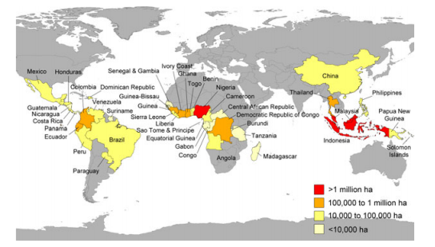
Fig. 1. Map showing the 43 countries around the world where oil palm is cultivated. Reprinted from (Koh and Wilcove 2008). Copyright © 2008 Blackwell Publishing, Inc., now John Wiley and Sons.
In light of the earlier plantation campaign period, the germination process of oil palm occurs on average in 3 months, in which the seedlings are grown in synthetic plastic bags and nurtured for a number of months. Upon reaching the age of one year and a height of one meter, the growing plants are transplanted into the field (main land) and the process is carried out continuously. The flourishing realization of the fast development of the palm plantation industries in Southeast Asia is attributed to the good tropical weather, suitability of land (fertile land), and low pathological threat or symptoms from planting the oil palm trees (Alam and Begum 2015).
Previous studies have suggested a rainfall of 1780 to 2280 mm as an average annual requisite and a temperature range between 24 to 30 °C, combined together for maximum yield. However, low humidity has been reported to hinder the stomatal opening and CO2 uptake (Smith 1989). Despite the fact that E. guineensis can be grown on a variety of soils, the growth of most of the species is usually unsuccessful or restricted at lower temperatures (i.e., below 15 °C) (Corley and Tinker 2003). Therefore, problems relating to prolonged fruiting, ripening of the fruits and stunted growth of the plant could be experienced in very low or cold temperatures. In a nutshell, for a successful cultivation of oil palm, an even distribution of rain fall is required in the soil (Hartley 1988).
Today, Malaysia and Indonesia are the world’s foremost producers and exporters of palm oil; thus the oil palm industrial activities of these countries are a success story. In this light, it is recognized that oil palm is one of the most essential commodities from these countries that has helped to facilitate the rapid development of their agriculture and economies (Barcelos et al. 2015). According to the Malaysian Palm Oil Council (MPOC), the palm oil activities in the country have impacted the lives of many citizens in several positive ways, especially by helping to decrease the poverty rate from 50% in the 1960s to below 5% in recent times. The palm oil industry has also provided direct jobs to about 0.6 million people, with another almost 0.3 million people working downstream. Similarly, it has been reported that approximately 25 million people’s earnings (in Indonesia) were directly or indirectly related to oil palm production, thus making oil palm-related activities a substantial way of reducing poverty in the country (Murphy 2014).
Furthermore, being the world’s second major palm oil producer and exporter, with nearly 4.5 million ha of land under oil palm cultivation (Ong et al. 2011), it is projected that annual production of palm oil in Malaysia could expand to around 15.4 million tons by 2020 (Sulaiman et al. 2011; Abdullah and Sulaiman 2013; Umar et al. 2014). Based on this projection, it is also expected that about 46.6 metric tons of lignocellulosic biomass (wastes) will be generated as a result of general oil palm industrial activities (Ng et al. 2012). It is feared that the by-products (wastes) produced by the oil palm industry are gradually creating disposal/environmental problems. For example, empty fruit bunches (EFB), palm pressed fibers (PPF), palm kernel shells (PKS), oil palm fronds (OPF), oil palm trunks (OPT), and palm oil mill effluent palm (POME) are all end products of oil palm activities and are generated in huge quantities (Sulaiman et al. 2011; Ng et al. 2012; Abdullah and Sulaiman 2013). This calls for a proper economical technological energy balance and environmental deliberations in a realistic manner to address the operation and use of oil palm wastes. Once this is achieved, Malaysia could be integrated among the leading countries or the center of renewable energy in the world through its huge oil palm-related biomass feedstock (Ong et al. 2011).
Even if the envisioned sustainable energy system is achieved, it is predicted that environmental matters would still be of concern to international communities. For this reason, researchers in the region have set this issue into consideration and proposed substantial solutions. Thus, in order to achieve an enhanced or maximized environmental protection to counteract the aftermath oil palm-related activities, Memari et al. (2017) have recommended that the ‘carbon pricing’ or ‘carbon tax’ must be sufficiently high to support manufacturers to apply innovative technologies in dealing with the feed stocks and their corresponding by-products. At the same time, the ‘carbon tax’ must also be low enough in order to encourage profitability. However, it was pointed out that excessive or high ‘carbon tax’ could create extra burden, while a too low ‘carbon tax’ could result to no emission reductions. In this light, it is therefore imperative for policy makers to design a system that could maximize environmental protection that has very low impact on the economic performance (Memari et al. 2017).
Compellingly, this has additionally necessitated scientists and engineers (especially in the region) to investigate ways to improve the exploitation and fabrication of valuable materials from the available wastes produced by the oil palm industry. This is meant to corroborate with the ‘wastes to wealth’ mantra and is geared towards a ‘zero-waste industry’ in the region. Despite the fact that the preparation of carbon nanostructures from those materials is still in its early stages, it is worth mentioning that a number of carbon-based nanomaterials, including graphene (Abd Rahman et al. 2014; Salifairus et al. 2016; Robaiah et al. 2017; Tahir et al. 2017), graphene oxide (Nasir et al. 2017), cellulose nanocrystals (Yogi et al. 2017), carbon nanotubes (Azira et al. 2013), vertically aligned carbon nanotubes (Suriani et al. 2009), nanostructured material (Abdul Khalil et al. 2011), oil palm shell nanoparticles (Abdul Khalil et al. 2016), epoxy nanocomposites (Abdul Khalil et al. 2013a), nanocellulose (Lani et al. 2014), nanofillers (Abdul Khalil et al. 2012), carbon nanospheres (Kristianto et al. 2015), nanoactivated carbons-filled-epoxy nanocomposites (Abdul Khalil et al. 2013b), porous carbon nanoparticles or PCNs for short (Ali et al. 2014), self-adhesive carbon grains, and highly porous binderless activated carbon (Farma et al. 2013), reportedly have been produced from those waste materials. The main goal of this review is to appraise the so-called oil palm-based industrial wastes/biomass, which were recently reported as new carbon (alternative) sources or precursors for the preparation of different carbon-based nanomaterials with strong potential in energy storage applications.
It is worth pointing out that this review was achieved through organized literature analyses using recursive phase defining search keywords related to the investigated area. The main keywords applied for searching the literature were as follows: Oil palm; Oil palm by-products; Environmental issues; Sustainable carbon sources; Carbon nanomaterials; Production; Nanoscience; Nanotechnology; and Energy storage application. However, taking into account the wide coverage of the investigated area i.e., three different topics namely: oil palm biomass, its availability, fundamental and detailed characteristics; nanomaterials in general; and nanomaterials from palm raw materials and their uses, the authors were thus unable to narrow or set a boundary on the years of publications of the articles that were used in the literature search. Nevertheless, the authors prioritized the studies that were published during the years 2000 to 2018.
General Perceptions on Nanomaterials
Despite the fact that there is no single globally accepted definition of nanomaterials, all the descriptions that are now applied by various associations or bodies (locally or internationally) incorporate a size range when describing ‘nanomaterial’. This is essential to be able to differentiate a ‘nano’ material from materials with external dimensions in the micrometre range or larger, and from the sizes at the atomic and molecular level. It is clear that properties of materials are directly or indirectly correlated to their size, which is why the latter is preferable and considered in defining nanomaterials.
In the chemical industry, the materials produced could further be manipulated and utilized to prepare new substances with entirely different sizes and properties from the original material. For example, iron girders used for building bridges can be miniaturized on a greatly reduced scale to silicon chips in microprocessors. Thus, it is now possible (using nanotechnology) to manipulate materials on the atomic or molecular scale to generate new materials with very small dimensions in nanometres. These new materials are called nanomaterials. A nanometre is measured as 1 × 10⁻⁹ metres, translating to a fraction of a billionth of a metre. Comparatively, this is well over 1000 times smaller than a silicon chip. It is known that when powdered material is transformed into nanomaterial, the miniaturization of the particles gives it new superior characteristics. These new properties are believed to be formed due to an increase in the surface area of the material, which in turn increases the rate of reactions that may occur on the surface of the material. The small dimensions of nanomaterials are also an important driver that paves the way to form intimate mixtures with other conventional materials, which is another way to modify the properties of the latter materials.
The European Union Commission’s definition of a nanomaterial is “a natural, incidental, or manufactured material containing particles, in an unbound state, as an aggregate, or as an agglomerate, where for 50% or more of the particles in the number size distribution, one or more external dimensions is in the size range 1 to100 nm” (Janez 2011). In the same report, further clarifications on the meaning of particle, agglomerate, and aggregate were also given. Particles were described as “a small piece of matter with defined physical boundaries.” Agglomerates were depicted as “a collection of weakly bound particles or aggregates where the resulting external surface area is the same to the total of the surface areas of the individual components.” Lastly, an aggregate was described as a particle consisting of strongly bound or fused particles (Janez 2011).
In this light, nanomaterials can be further described as materials that have distinctive or novel properties, due to their nanoscale configuration. The materials are usually produced by the integrating or structuring of nanoparticles. They are subdivided into nanopowders, nanocrystals, and nanotubes, and can have zero, one, two, or three dimensions on the nanoscale. The current interest in nanomaterials is ascribed to the small-scale dimension of the materials. Materials with nanoscale size have different properties as compared to the bigger scale, which can be attributed to increased surface area to volume ratios. In essence, increased interaction and reactivity is expected with these materials and thus there is the potential to use less (Kuno 2005) of the material.
Therefore, it can be deduced that a nanomaterial’s size is the most important property of these materials, although other features, such as shape and surface morphology of the material, are also very crucial in determining their properties. According to Ventola (Ventola 2010, 2012) the overall properties of nanoparticles could be measured using the properties of the individual constituents (composition of the nanoparticle) and the interaction among themselves and the surrounding position.
Aside of those special properties of nanoscale materials that have attracted researchers’ and manufacturers’ attentions as previously described, it is also worth pointing out that those unique attributes have also rendered some of these materials to characteristically deviate from the conventional materials under certain circumstances. For this reason, many forms of these nanostructured materials are now considered as detrimental (due to their chemical formation) based on the Toxic Substances Control Act (TSCA) of the environmental protection agency (EPA) of the USA. Thus, in order to properly checkmate and thwart the operation or production of new noxious nanoscale substances for public and environmental safety, the TSCA has enacted stringent policies that mandated producers/ suppliers of new chemical substances to present detailed information of their products to the Agency for critical evaluation before commercialization. In this connection, several other organizations, e.g. International Organization for Standardization (ISO), the Organization for Economic Cooperation, and Development (OECD) among others (that act as watchdogs) have now been synergistically associated with EPA and engaged in a multitude of assignments to fully unravel the properties and impending threat or hazards of nanomaterials and nanotechnology-related emerging issues.
Nanoscience and Nanotechnology at a Glance
From the previous understanding of nanomaterials, nanoscience can be described as the investigation of the features and properties of matter at the nanoscale (Mulvaney 2015). Hence, this study is predominantly centered on the distinctive, size-dependent properties of solid-state materials (Mulvaney 2015). To prepare materials at a nanoscale, a novel approach is required. For this reason, both bottoms-up and top-down methods are commonly used. Similarly, it is also imperative that modern advanced characterization techniques are employed for the characterization of these materials (Weiss 2012).
In contrast, nanotechnology is made up of diverse parts that involve processes of isolation, recombination of the isolated or separated items or scattered nanomaterial into a single or whole mass (that have combinations of properties that are different from those of the original), as well as disfiguration or deformation of those materials by an atom or a molecule. In simple terms, nanotechnology can be described as the ability to manipulate a single nanoscale object. Norio Tanaguchi (1974), a Japanese scientist, was the pioneer researcher who coined the word nanotechnology. He generated the term while attempting to explain the notion of semiconductor processes taking place on a nano level. He maintained that the concept of nanotechnology encompasses the processing, separation, consolidation, and deformation of materials on a nano scale (Tanaguchi 1974) as previously mentioned.
In summary, nanoscience and nanotechnology can be described as the scientific and engineering of materials at the molecular level. It is a general expression for a collection of technologies, processes, and techniques that entail the manipulation of matter at the smallest scale, usually from 1 to 100 nm (Vaddiraju et al. 2010; Ventola 2012). Nanostructures or nanomaterials research has now become widely spread among various disciplines (e.g., chemistry, physics, biology, materials science and engineering, etc.) in which scientists and engineers use and/or control matter at the atomic and molecular level with the aim of achieving materials and systems with extensively superior properties (Vaddiraju et al. 2010). Consequently, carbon nanomaterials or allotropes (the focus of this review) have a special place in nanoscience and nanotechnology, considering their outstanding chemical, mechanical, thermal, and electrical properties. For this reason, they hold huge potentials in areas as diverse as sensors, drug delivery, super-strong composite materials, energy storage and conversion, thermal conductivity enhancement, supercapacitors, paints, and nanoelectronics (Stankovich et al. 2007; Zhu et al. 2011; Bonaccorso et al. 2015; Gadipelli and Guo 2015; Chen et al. 2016; Notarianni et al. 2016; Nasir et al. 2018).
Contemporary Carbon Nanomaterials
Carbon-based nanomaterials or nanostructures, particularly graphene and its derivatives (Novoselov et al. 2004), carbon nanotubes (CNTs) (Iijima 1991), and fullerene (Kroto et al. 1985; Smalley 1991), have attracted researcher’s attention worldwide. These materials, especially CNTs, and the recently discovered 2D material (graphene), and other graphene-related substances, have become special materials for nanotechnological applications (Fig. 2). For example, graphene and CNT-based hybrid materials have now become key players in the design, preparation, and commercialization of different types of devices such as chemical sensors, electronics, optoelectronics, and energy storage devices (Georgakilas et al. 2015).
The use of nanomaterials/or nanoparticles and nanotechnology can be traced back to primordial times (Heiligtag and Niederberger 2013), with modern researchers referring to it as “ancient nanotechnology”. In the Roman Empire, the colloidal particles of silver and gold (now known as nanoparticles) were used for the production of glasses and believed to be responsible for the special properties associated with the produced materials. After the “ancient nanotechnology” epoch, the next major progress made on nanoparticles investigation was attained by Michael Faraday about fifteen decades ago. His discovery on the interaction of light with metal nanoparticles is recognized to be the foundation of the contemporary colloid chemistry and the evolution of current research in nanoscience and nanotechnology (Heiligtag and Niederberger 2013). Currently, carbon-based nanomaterials are not only the leading focus of intense fundamental materials research, but are also slowly encroaching into many people’s day-to-day lives. Several important breakthroughs could be achieved by miniaturizing or down-sizing the contemporary existing structures into the nanometer scale or by creating novel types of nanostructures (Vaddiraju et al. 2010).
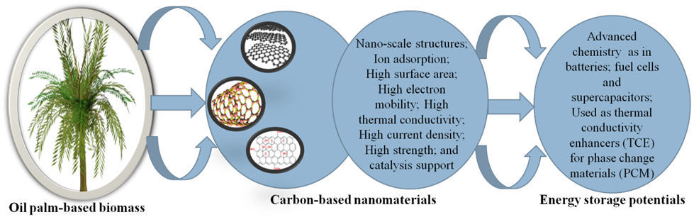
Fig. 2. Features of the oil palm waste-derived carbon nanostructures and their resultant energy storage applications
In 1959, Richard Feynman (a Nobel Laureate for Physics in 1965) brought to light the scientific concept of ‘nano’ in his prominent statement that there is plenty of room at the bottom, while addressing the audience in a conference of the American Physical Society (Feynman 1960). In the same lecture, he expressed that “the principles of physics do not speak against the possibility of maneuvering things atom by atom.” This famous address is believed to be the foundation or stepping stone for K. E. Drexler who, in the middle 1980s, exemplified the likelihood of developing nanoscale devices atom-by-atom as hypothesized by Feynman (Drexler 1986).
Since then, scientists have embarked on investigating the physical and chemical properties of monocrystalline materials (Chen et al. 1998; Weiyou Yang et al. 2005; Sun et al. 2016). They were thrilled to observe features that strikingly differ from those of the bulk materials. These nanoparticles demonstrate a broad range of size dependent properties that were undoubtedly attributed to the molecular orbitals of the solid materials.
When the size of the materials is shrunk down to nanometer scale, quantization effects will emerge due to the confinement of electron movement (Georgakilas et al. 2015). This leads to discrete energy levels depending on the size of the materials, which is noted from the quantum mechanics principles. The quantized electronic states of nanostructures decide their electrical and optical properties, and they influence the physical and chemical properties as well. For this reason, nanostructured materials exhibit different properties from those of their counterparts, such as bulk materials (Ventola 2012).
In this light, the properties of carbon nanomaterials also rely on their atomic structures and interactions with other materials. Hence, the ability to control the dimension and composition of nanostructured materials could pave the way for manipulating materials’ properties to meet the needs for a variety of applications (Georgakilas et al. 2015).
Classification of Carbon Nanomaterials by Dimension
The materials under discussion encompass complete and diverse crystallographic structures with various shapes, dimensions, geometries, and chemical bonds (Fig. 3). Therefore, carbon-based nanomaterials can be divided into two general groups based on the primary types of covalent bonds connecting their carbon atoms.
The first group according to this classification comprises of all the graphenic nanostructures, which are predominantly composed of sp2 carbon atoms that are compactly crammed or arranged in a hexagonal honeycomb crystal lattice. Additionally, in some instances, they could also incorporate some C-C (sp3 carbon atoms) at defect sites. A typical example of nanostructures under this group are, but not limited to, various sorts of graphite, graphene, other graphene-related and derived materials, carbon nanotubes, nanohorns, onion-like carbon nanospheres, C-dots, carbon-based aerogels, carbon fibres, and their composites (Georgakilas et al. 2015). One of the key reasons for having all these graphenic nanoallotropes is ascribed to the versatility and utility of carbon to catenate by forming three indistinguishable covalent bonds with other carbon atoms using sp2 orbitals (Nasir et al. 2018). As a result, a two-dimensional (2D) lattice of tightly compacted hexagons is formed. For example, 2D hexagons and a one-atom-thick sheet of sp2-hybridized carbon, arranged in a hexagonal lattice (popularly known as graphene), contain all the features present in this group. It is worth emphasizing that the graphenic/graphitic nanoallotropes in this group largely involve graphene as the elementary unit of their structure. It should also be noted that the dimensions of the layer are usually not predetermined but are generally in excess of 500 nm.
The second group of carbon nanostructures is made up of both C-C and C=C (i.e., sp3 and sp2 carbon atoms) bonds in various ratios and contains combinations of amorphous and graphitic regions, or involves primarily sp3 carbon atoms. Despite the fact that some carbon dots containing agraphitic (nongraphitic) structures can also be considered as examples of this group, nanodiamonds are the only prominent carbon nanostructures belonging to this group that have been thoroughly described. It should be noted that these nanoforms are generally not fabricated from graphene parts or monolayers, such as carbon nanotubes (Georgakilas et al. 2015). This trait could be considered as the main attribute that distinguishes the second group from their counterpart (i.e., the first group).
Moreover, carbon nanoallotropes can also be classified based on their morphological features. For example, carbon nanostructures with clear internal void spaces, such as carbon nanotubes, nanohorns, and fullerene, could be categorized as group one based on this classification. It is perceptible that the empty internal spaces of those carbon nanostructures allow the hosting of foreign or guest molecules, metals, atoms, or other nanostructures. Under this condition, a new nanoenvironment can be created and as a result certain chemical reactions may possibly occur or be facilitated. The second group, according to this classification, is directly the opposite of the first group or group one above. It encompasses all carbon nanostructures that do not have internal void spaces such as carbon dots, graphene, graphene quantum dots, and nanodiamonds (Georgakilas et al. 2015).
For the purpose of this paper, classification based on the structure or dimensionality of the carbon nanostructures is considered and prioritized. In this way, carbon nanostructures occurring in various dimensions can be identified (Fig. 3). For instance, 0D (zero dimensional) nanoallotropes, such as carbon dots, fullerene, and nanodiamonds, can be distinguished from their counterparts, i.e., 1D (one dimensional), such as carbon nanofiber, carbon nanotubes, etc., and 2D nanostructures, such as few-layer graphenes, graphene, and graphene nanoribbons (Georgakilas et al. 2015).
In recent years, the controlled manipulation, reduction, and modification of sample dimensions into a small number of nanometers is attracting increased attention. As explained earlier, researchers are captivated by the nanoscale due to the fact that physicochemical properties of materials in the nanoscale change considerably from those at a larger scale or in bulk. Therefore, nanoscaled materials could be designed and developed through the modified, controlled, and size-selective production of nanoscale building blocks with tunable and enhanced physical and chemical properties (Abdul Khalil et al. 2011).
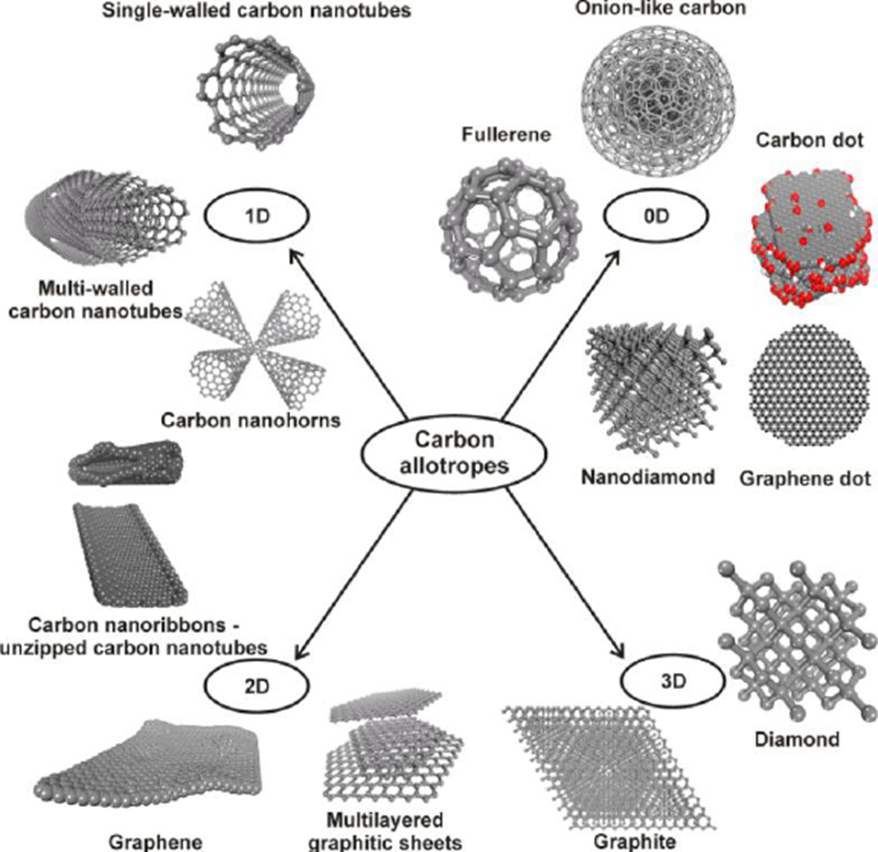
Fig. 3. Classification of carbon nanostructures based on their dimensionality (Georgakilas et al. 2015, reprinted from an ACS publication)
Figure 3 depicts a summary of the well-known carbon nanostructures or allotropes. These range from 0D allotropes, such as carbon dots, graphene quantum dots, fullerenes, nanodiamonds, and onion-like carbon, to 1D, such as carbon nanohorns, single-walled, and multi-walled carbon nanotubes, and lastly to 2D nanostructures such as graphene nanoribbons, multilayer graphitic nanosheets, and graphene. One key advantage ascribed to this classification is that it reveals the different morphological and structural arrangements of sp3 and sp2 carbons in each case. Furthermore, it is fascinating to infer that some of these nanoallotropes are well-founded (in terms of stability) and demonstrate distinctive features that could be affected by the content of their guest elements or other functional groups (Georgakilas et al. 2015). Thus, the presence of some non-carbon atoms in many of the 0D nanostructures presented above has intense and unique effects on their properties.
In summary, carbon nanomaterials can be divided into 0D, 1D, and 2D nanostructures due to their shapes, which show restricted motion of carriers in all three dimensions, respectively. However, the division could be extended to some special types of activated carbons that can be considered as three-dimensional (3D) materials (Table 2) due to the presence of nanopores occurring in micro- and mesoporous forms in their structures (Fig. 4).
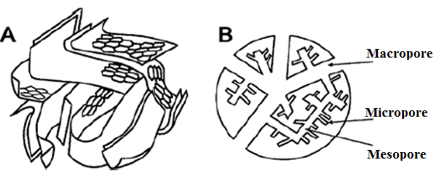
Fig. 4. A simple portrayal of (A) the 3D and (B) the 2D structure of activated carbon (Rodríguez-Reinoso 1998). Copyright © 1998 Published by Elsevier Ltd.
It is worth noting that all porous materials have been subdivided into three main categories based on the IUPAC rules (Sing 1985). For instance, microporous materials encompass all materials exhibiting a pore diameter lower than 2 nm, while mesoporous materials exhibit a pore diameter ranging between 2 and 50 nm, and macroporous materials have pore diameters above 50 nm. In some instances, materials have a pore size slightly greater than 100 nm.
Table 1. Classification of Pore Size and Adsorption Mechanism Based on the IUPAC Recommendation 1984

CARBON NANOSTRUCTURES INNOVATIVELY/RESOURCEFULLY DERIVED FROM PALM OIL INDUSTRIAL WASTES
The main purpose of this paper is to review and discuss the new alternative carbon precursors for the preparation of carbon nanostructured materials. Interestingly, oil palm wastes as a derivative of biomass resources are adequate candidates as raw materials for carbon products. They have recently been used for the production of important carbon nanomaterials (Abdul Khalil et al. 2016; Nasir et al. 2017). Evidence of its potential in the production of various carbon nanomaterials has been described in literature and is presented in Table 2.

Fig. 5. FESEM micrographs of vertically aligned carbon nanotubes grown on silicon substrate: (a) peeled off bundle of dense carbon nanotubes and (b) side view of the aligned carbon nanotubes (Suriani et al. 2009) Copyright © 2009 Elsevier B.V.
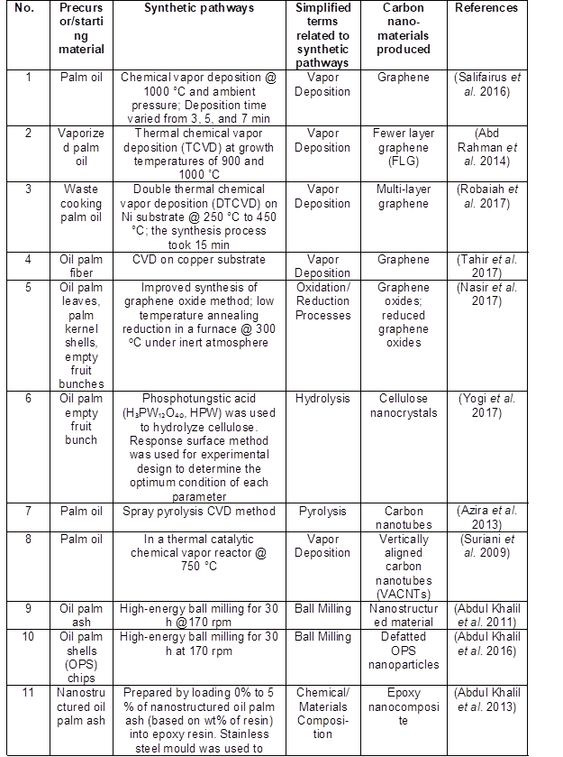
Table 2. Literature Report on the Synthesis of Carbon-based Nanomaterials from Palm Oil Industry Wastes Using Different Synthetic Pathways
As outlined earlier, the reason why attention is widely given to functional carbon-based nanomaterials is because of their exceptional combinations of physical and chemical properties. These include, but are not limited to, electrical and thermal conductivity, high mechanical strength, and good optical properties (Chen et al. 2011; Georgakilas et al. 2015; Nasir et al. 2018). For this reason, concerted research efforts are being exerted towards the production of these materials tailored for different industrial applications, such as energy storage and conversion, high-strength materials, and electronic devices. These valuable properties of carbon-based nanomaterials were also dynamically explored in various areas of biomedical applications (Yang et al. 2013).
The use of low-cost carbon-based materials that are genetically inclined to oil palm precursors employed to prepare carbon nanomaterials has been described in Table 2. Despite the fact that these materials can be synthesized from various oil palm-based precursors, their real applications are still extremely scarce in available literature. For this reason, the authors focused more on the synthesis of these materials as provided in Table 2. For example, Suriani et al. (2009) exploited natural palm oil precursor for the growth of vertically aligned carbon nanotubes on silicon substrate using thermal catalytic chemical vapor reactors (Fig. 5). In the typical pyrolysis process, as conducted by the authors, the precursor was pyrolyzed to approximately 450 °C, which in effect putrefied the ferrocene to iron particles. Further decomposition of the palm oil molecules into compounds containing carbon, hydrogen, and oxygen molecules (generally referred to as hydrocarbons) also occurred concurrently with the former process. During the process, the hydrocarbon vapor was ultimately mixed with the nanosized iron catalyst, settled on the silicon substrate, in the fabrication area where the heating temperature was maintained at 750 °C. As a result, the dissolution of carbon into the iron particles transpired and, finally, hydrogen and oxygen gases were released. By this method, carbon nanotubes of approximately 90% purity were produced.
In another interesting report, Salifairus et al. (2016) presented the effect of synthesis time on graphene growth from palm oil as a green carbon precursor. The graphene growth was conducted at an ambient pressure in a typical chemical vapor deposition (CVD) system at 1000 °C by varying the deposition time of the green precursor from 3, 5, and 7 min, respectively. In the same way, a similar carbon nanomaterial (with a few layers of graphene in this case) was obtained by different authors through thermal chemical vapor deposition on nickel catalyst at growth temperatures of 900 and 1000 °C, respectively (Abd Rahman et al. 2014). However, according to yet another report (using a similar precursor as used by the previous authors), when DTCVD on Ni substrate was carried out at temperatures ranging between 250 to 450 °C, a double layer graphene was produced (Robaiah et al. 2017). Furthermore, graphene was also reported to have been generated from oil palm fiber using the CVD method on copper substrate (Tahir et al. 2017). In another recent article (Nasir et al. 2017), the authors reported the synthesis of graphene oxide and reduced graphene oxide from various oil palm-based precursors (i.e., oil palm leaves, palm kernel shell, and empty fruit bunch) using the improved synthesis in the graphene oxide method and low temperature annealing reduction methods. In the reduction process, the GO samples were reduced at 300 °C in a furnace under nitrogen gas for 1 h. Several other forms of carbon nanomaterials, such as nanocellulose, nanofiller, carbon nanospheres, cellulose nanocrystal, epoxy nanocomposite, and nanoactivated carbon, were all reported to have been synthesized from various oil palm-based precursors and methods as shown earlier in Table 2.
CHARACTERIZATION TECHNIQUES FOR CARBON NANOSTRUCTURES
This section highlights the physico-chemical characterization techniques that are usually used to explore the properties of carbon nanostructured materials. Despite the fact that the tools and the process for the characterization of carbon nanomaterials are sufficient, sometimes there can be associated challenges. Accordingly, for accurate data interpretation, it is important to employ proper analytical techniques and sample preparation methods. The main aim of material characterization is the screening of mechanical, thermal, optical, and electronic properties of materials that are being integrated in diverse manufacturing products that affect daily human life. Despite the fact that there are several analytical techniques that are currently utilized in different research fields for materials characterization, in this review the researchers focus on eight (state-of-the-art) major techniques that are frequently used to evaluate and characterize carbon nanomaterials for easy data analysis and interpretation. These techniques include, viz., Raman spectroscopy (RS), X-ray diffraction (XRD), transmission electron microscopy (TEM), UV-visible absorption spectroscopy, photoluminescence spectroscopy, Fourier transform infrared spectroscopy (FTIR), thermogravimetric analysis (TGA), and the Brunauer–Emmett–Teller (BET) surface area analyser.
Raman Spectroscopy
This technique provides a means by which molecules can be recognized. It is performed or applied to essentially examine the structure and chemical composition of a sample. This could be gel, slurry, powder, solid, liquid, or gas (Welsh et al. 1955; Ferrari and Robertson 2001; Ferrari 2007; Childres et al. 2013; Ganguly et al. 2014). In the context of this paper, using the Raman spectroscopy technique for example, Suriani et al. (2009) used Raman spectroscopy to characterize vertically aligned carbon nanotubes grown with palm oil-derived precursor on a silicon substrate. Based on the results obtained from the analysis, the researchers discovered that the sample contained a combination of single- walled carbon nanotube (SWNT) and multi-walled carbon nanotube (MWNT). The graphitic nature of the materials was investigated using the D- and G-bands at around 1346 cm−1 and 1583 cm−1, respectively. Furthermore, the presence of SWNTs was confirmed from the lower frequency radial breathing modes (RBM) at 219.4 cm−1, 277.2 cm−1, and a weak peak at 395.5 cm−1 (Fig. 6). It is worth emphasizing that the diameter, d, of the SWNTs can also be examined from the location of the RBM peak.
Currently, it is fascinating to observe that the Raman instrument has been widely accepted as an essential analytical tool that can be used as a research instrument for a broad range of applications such as thin films, polymers, semiconductors, forensic science, and pharmaceuticals. More importantly, in the field of carbon and materials sciences, it is used for non-destructive identification and molecular fingerprint studies of carbon-based materials as demonstrated and explained earlier. It is generally believed that the expansion of materials science in the 21st century primarily relies on the investigation of the basic structure of all the allotropic kinds of carbon such as diamond, graphite, carbon nanotubes, fullerenes, graphenoids, and graphenic-like carbon nanomaterials. Thus, physicochemical studies of these materials together with their degree of perfection may be used to understand and subsequently harness the informational potential of their practical applications. The fact that these carbon nanomaterials provide a wide range of significant properties related to electrical conductance, thermal resistance, and excellent mechanical strength, has allowed them to be used as indispensable materials for a wide range of industries. It is worth emphasizing that a significant concern and increased interest in the processing and customization (modification) of these materials has demanded for suitable methods that could be employed in their characterization. Interestingly, the technique under discussion here (Raman spectroscopy) has been tested experimentally and found suitable for most of the characterization requirements with these materials (Hodkiewicz 2005).
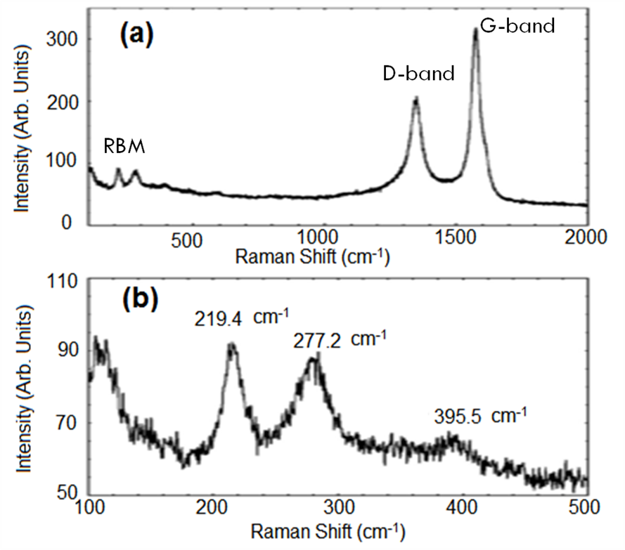
Fig. 6. Raman spectra of vertically aligned carbon nanotubes prepared with natural palm oil: (a) Microraman spectrum illustrating the radial breathing modes (RBM), the D line, and the G line of CNTs, and (b) Micro Raman spectrum indicating the RBM modes of SWNT (Adapted from Suriani et al. 2009). Copyright © 2009 Elsevier B.V.
As such, the characterization of graphene and other carbon nanomaterials can be easily done with Raman spectroscopy, which is capable of differentiating between the number of layers, order, and various structures of carbon nanomaterials (Ferrari et al. 2006; Childres et al. 2013; Budde et al. 2016). Differentiation of the number of layers of graphene is normally achieved by taking the I2D/IG ratio from the Raman spectra. For example, monolayer graphene usually has I2D/IG value > 1, bilayer graphene has I2D/IG = 1, while multilayer graphene has I2D/IG < 1. Raman spectroscopy is also promising in the assessment of the purity and quality of nanomaterials. As seen earlier, the Raman technique has now become widely used to collect radial breathing mode spectra in carbon nanotubes and the bands associated with graphitization and defects (i.e., G-band/D-band) in graphene. Thus, the technique is now used as a perfect means to characterize material structures in carbon science.
To understand the mechanism (Fig. 7), Raman spectroscopy is a light scattering technique that encompasses a process where a photon of light strikes a sample to generate scattered radiation of different wavelengths (Raman 1928). This vibrational spectroscopy method is employed to record and compile a special chemical pattern or fingerprint of molecules. Every molecule possesses its own unique set of vibrational energy levels. Therefore, the photons emitted have distinctive wavelength shifts. To identify what is in the sample, a vibrational spectroscopy is used to gather and examine the wavelength shifts. Hence, the different peaks in the spectrum correspond to different Raman excitations due to different functional groups.
The fundamental theory of the Raman Effect was developed many years ahead of its discovery. As far back as 1878, anomalies in the fluorescence emissions had been explained by scientists. Quantum mechanics were applied to predict the Raman Effect on the molecules. When light quanta of energy hυo strikes matter, a small fraction of the incident radiations is scattered, either elastically (Rayleigh scattering) or in-elastically, giving rise to emit photons of energies either higher or lower than that of the incoming radiation. This process is referred to as the Raman Effect. The photons emitted at the lower energy, hυo to hυ1, are called stokes Raman photons, while those that gain energy at higher frequencies are termed antistokes. In general, the emitted photon can gain or lose energy from the atomic/molecule vibration (phonon) mode. Both processes (stokes and antistokes) are possible, and their intensities are always linked.
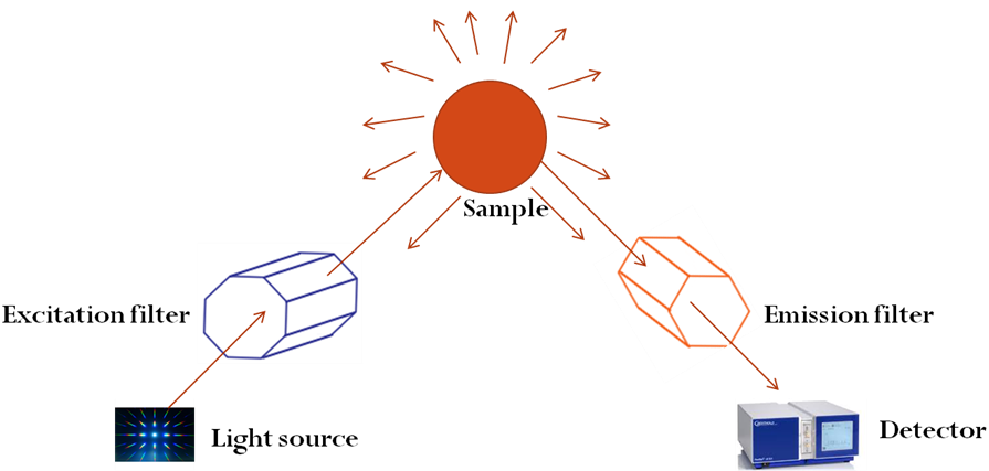
Fig. 7. Simplified setup of a Raman (light scattering) experiment showing how the equipment works on the sample
Historically, Sir Chandrasekhara Venkata Raman (1888 to 1970) and his team were the pioneer researchers that experimented and reported the inelastic scattering of light (Raman 1928). For this reason, the Raman Effect, or in general Raman spectroscopy, was named after him, and the finding earned him the Nobel Prize in physics in 1930 (Krishnan and Shankar 1981). To further understand how this novelty was achieved using sunlight, the researchers used a narrow band photographic filter to produce monochromatic light, and a “cross filter” to block the monochromatic light (Raman 1928), as shown in Fig. 7. They were surprised that some fraction of light had acquired new differential frequency and passed through the “crossed” filter. It should be noted that the technique (Raman spectroscopy) deals with molecular and crystal lattice vibrations. As a result it is very susceptible to the chemical surroundings, bonding, and crystalline structure of the analyzed sample, phase, and composition of the material (Childres et al. 2013). For this reason, it is now used for the analytical investigation of materials in any physical state, for example solid (amorphous or crystalline), liquids, gases, and solutions. Ever since its invention, the instrument has become a spectacular medium for the investigative study of various materials, especially carbon-derived materials in recent decades (Hodkiewicz 2005).
It is imperative to note that the method is generally susceptible to covalent bonds that are highly symmetrical in nature with minimal or negligible natural dipole moments. The C-C bonds that formed these materials were in conformity with this condition. For this reason, Raman spectroscopy is highly sensitive to these materials, hence providing essential structural information of the materials. As earlier described, the technique can detect very small structural changes, making it a suitable investigative tool for the characterization of carbon nanostructured materials.
X-ray Diffraction
X-rays were discovered by a German physicist Wilhelm Conrad Röntgen in 1895, who was honored with the Nobel Prize for Physics in 1901. However, the procedure of X-ray diffraction using crystals was exposed by Max von Laue in 1912, and this discovery earned him the Nobel Prize for Physics in 1914. In 1915, another Nobel Prize for Physics was conferred to Lawrence Bragg and his father, William Henry Bragg for the explication of the X-ray diffraction phenomenon. Hence, X-ray technology has been in existence for several decades and its invention and advancement has transformed several areas of modern science and technology. Today, X-ray diffraction instruments are used for the determination of crystallinity (i.e., crystal structures of materials), amorphous state, and purity of the sample (West 1987; Alibe et al. 2018). X-ray analysis methods, especially diffraction and reflectometry, are some of the most notably used analytical techniques for the detection of crystalline properties of materials. Several other properties that are significant drivers for many industrial applications, such as surface roughness, materials strain, stress, texture, density, and phase composition, can also be evaluated using this technique.
To further understand this technique, X-rays are electromagnetic radiations with a wavelength in the range of 0.01 to 100 Å. Therefore, for X-ray diffraction the wavelength also falls within the given range, which is analogous to the inter-atomic spacing (d spacing) in a crystal. For example, the diffraction generally occurs when a material with an ordered arrangement of atoms or molecules is struck by X-ray radiation, as a result, the diffraction pattern generated is unique for a particular phase of the material (He 2009).
Apart from synchrotron radiation sources, the process of X-ray production in almost all diffraction experiment results from bombarding a metallic target, such as copper or molybdenum, with accelerated electrons (30 to 50 kV) at the X-ray tube. The electrons transmit their energy to the atoms of the target and ionize electrons from the K shell (1s orbital) of the target atoms, creating an empty spot in the shell. This vacancy is generally filled by an electron from the outer shell (2p or 3p orbitals) and the energy released in the transition appears as characteristic X radiation. For copper, the Kα (2p→1s) and K (3p→1s) transitions have wavelengths of 1.5418 Å and 1.3922 Å, respectively. The Kα transition occurs much more frequently than the K transition, which is an indication that more intense Kα radiation is used in diffraction experiments (West 1987; Guinebretière 2013).
When a crystal is irradiated with a beam of X-photons that has a wavelength similar to the inter-atomic separation, it emits an X-ray beam with a wavelength equal to that of the incident beam, which then scatters. The scattered waves interfere to generate diffracted waves with higher intensities. The analysis of the distribution in space of the diffracted intensity allows for characterization of the structure of the materials being examined (Guinebretière 2013). Bragg’s approach has been used to study diffraction by crystals. It considers crystals built up in layers or planes, with each serving as a semi-transparent mirror. Some of the X-rays are reflected off a plane with the angle of reflection equal to angle of incidence, while the rest are transmitted to be subsequently reflected by succeeding planes.
A typical X-ray diffraction experiment entails an X-ray source, the sample to be examined, and a detector to spot and record the diffracted X-rays. Within this broad configuration, there are variables that control the different X-ray techniques (West 1987). The principle of the powder technique is as follows. Characteristically, a monochromatic beam of X-rays strikes a finely powdered sample with various lattice planes arranged in random orientation to facilitate diffraction in all directions. Nevertheless, only the diffracted waves that satisfy Bragg’s law give rise to pattern formation (Fig. 8). The diffracted beams can be detected either by surrounding the sample with a strip of photographic film (Debye-Scherrer and Guinier focusing methods) or by means of a movable detector, such as a Geiger counter, connected to a chart diffractometer recorder (West 1987).
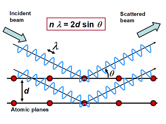
Fig. 8. Principle of X-ray diffraction
In a direct correlation to the context of this paper, the technique has been used to characterize carbon nanomaterials. As demonstrated in Fig. 9, the technique was reported to have shown the overall oxidation of graphene oxides prepared from oil palm-based feed stocks.
For the first time, the authors (Nasir et al. 2017) were able to examine the crystallographic phases of the graphene oxides prepared from oil palm leaves (GOOPL), palm kernel shells (GOPKS), empty fruit bunch (GOEFB), and commercially purchased graphite (GOCG), using this technique. Initially, the graphite-like material showed a basal reflection (002) peak at 2θ = 25° (Fig. 9a) and after oxidation of the graphite, the 002 reflection peak moved to the lower angle (2θ = 10.3°). The formation of the GO was confirmed by the strong and weak diffraction peaks at 2θ = 10.3° (Fig. 9b) due to the chemical oxidation of the graphite-like material (Nasir et al. 2017).
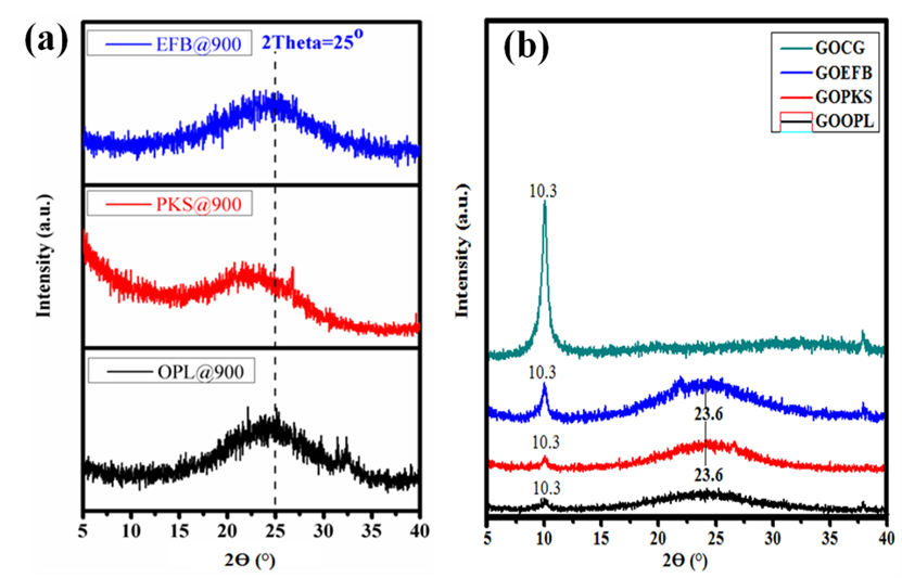
Fig. 9. X-ray diffraction patterns of (a) graphite-like material prepared from different oil palm-based precursors and (b) graphene oxide fabricated from (a) above (Adapted from Nasir et al. 2017).
Transmission Electron Microscopy (TEM)
The development of electron microscopy was conceived because of the drawback of light microscopes, which are limited by the physics of light to 500× or 1000× magnification and a resolution of 0.2 micrometers. A transmission electron microscope was the first type of electron microscope developed and was designed based on the light transmission microscope except that the electron focused beam is used instead of light. The instrument was invented by Max Knoll and Ernst Ruska in Germany in 1931 (Voutou et al. 2008). Descriptively, an electron source (cathode-ray tube or filament) is usually used to generate highly excited electrons in a vacuum and accelerated towards a given specimen by a potential difference. A series of magnetic lenses and metal apertures are used to focus electrons into a monochromatic beam. The accelerated beam is exposed to the sample and the transmitted portion is focused by a set of objective and projector magnetic lenses into an image on a fluorescent screen. Usually, the particle size and size distribution of the samples are examined from the transmission electron microscopy micrographs using 100 kV or a variation depending on the device. The average size and size distribution of nanoparticles could be evaluated with TEM images using image tool software, taking into consideration at least 100 particles for each sample. The TEM sample is usually prepared via ultrasonic dispersion of the carbon nanoparticle (powder form) in acetone, followed by depositing a drop of the substance into copper grids so the acetone can further be evaporated by air drying.
Other microscopy instruments, such as scanning electron microscope (SEM), field emission scanning electron microscopy (FESEM), and high-resolution transmission electron microscopy (HRTEM), are also useful ways in generating images and chemical information from the carbon nanomaterials samples.
UV-visible Absorption Spectroscopy
This is another useful technique for measuring the absorption of light (between the wavelengths of 190 nm and 800 nm) by materials, which transpired from electronic transitions occurring in the analyte molecules and complex ions. The possibility of many electronic transitions (resulting in continuous spectra) occurs due to vibrational and rotational energy levels that are superimposed on the electronic levels (Kenkel 2003). It is important to note that the absorption spectra are very sensitive to dimension and surface modification as well as particle concentration and is applicable for both the qualitative and quantitative measurements of samples. Details of the principle of UV-visible spectroscopy can be found elsewhere (Kenkel 2003).
Photoluminescence Spectroscopy
Photoluminescence spectroscopy (PL) is a selective and highly sensitive probe of discrete electronic states that provides electrical characterization. The characteristic features of the emission spectrum allow for the identification of surface, interface, and impurity levels. Equally important is that essential information about the quality of surfaces and interfaces could be generated from the intensity of the PL signals (Gfroerer 2000). The mechanism transpires when light of passable energy strikes a material (e.g., carbon nanomaterials), which in effect facilitates photons absorption and excitations of electrons. After reaching climax, gradually, these excitations slow down, and the electrons return to the ground state. Thus, if radiative relaxation takes place, the resultant emitted light is characterized as PL. Throughout the process, energy can be saved or conserved if the emitted photons have less energy in contrast to their counterparts (excitation photon). Consequently, this light can be composed and analyzed to generate fundamental information about the photoexcited material. Furthermore, the transition energies provided by the PL spectrum could be used to examine electronic energy levels. Moreover, the relative rates of radiative and nonradiative recombination can also be measured from the PL intensity. However, when the form or feature of the analyzed material differs spatially, the PL signal will adjust with excitation position. The versatility of PL in the characterization of surfaces is attributed to its excellent sensitivity to discrete electronic states, many of which lie near surfaces and interfaces. Equally important, defects and impurities can be examined by discrete energy levels that lie within the band gap. Subject to defects or impurities, the state serves as a donor or acceptor of excess electrons in the crystal.
FTIR Analysis
In addition to its application for various types of sample analysis, this instrument is also used for the identification of functional groups or chemical bonds that are either organic or inorganic in the carbon nanomaterial sample. The mechanism is similar to the other types of energy absorption. For example, when molecules absorb infrared radiation, they become excited to a higher energy state, and the process is quantized. The energy range of infrared radiation usually matches to the range encompassing the stretching and bending vibration frequencies of the bonds in most covalent molecules. In the absorption process, those frequencies of infrared radiations, which match the natural vibrational frequencies of molecules, can be absorbed, and the energy absorbed serves to increase the amplitude of the vibrational motions of the bonds in the molecule. However, not all bonds in molecules are capable of absorbing infrared energy, even if the frequency of the radiation exactly matches that of the bond motion. Only those bonds that have a dipole moment are capable of absorbing infrared radiation and symmetric bonds. For example, H2 or Cl2 do not absorb infrared radiation. The infrared spectrum can be used for molecules as a fingerprint can be used for humans. A second and more important use of infrared spectrum is to determine structural information via functional groups that are presence in a molecule (Pavia et al. 2001). For example, infrared spectra of carbon nanomaterials can be recorded using a FTIR spectrometer (Perkin Elmer model) at wavelengths of 400 to 4000 cm-1.
Thermal Analyzer
A thermal analyzer is usually used to determine the thermal stability of carbon nanomaterials as they are heated. With thermogravimetric analysis (TGA), a proximate analysis can be performed to determine the amounts of volatile matter, moisture, ash, and fixed carbon contents in the carbon-based materials. Taking activated carbon as an example, the activation studies can be performed with TGA to determine suitable conditions for the activation of carbon samples. Reactivity is examined in the TGA using air, carbon monoxide, or steam. Normally, the sample is heated in nitrogen to a programmed reaction temperature and once the temperature and weight have stabilized, an appropriate reaction gas is substituted for the N2, and weight loss is verified as a function of time. Therefore, thermal analysis plays an important role in developing carbon nanomaterials by providing fundamental data that is essential in the material processing, production, characterization, and application.
Brunauer–Emmett–Teller (BET) Surface Area Analysis
The BET theory was developed by Stephen Brunauer, Paul Emmett, and Edward Teller in 1938 (Brunauer et al. 1938). However, before the advent of this theory, the Langmuir theory was commonly used for surface area analysis, which was developed by Irving Langmuir in 1916. The BET theory was developed by expanding the Langmuir theory, which generally relates the monolayer adsorption of gas molecules (adsorbates) onto a solid surface to the gas pressure of a medium above the solid surface at a fixed temperature. In recent years, the BET analysis has been effectively used for the measurement and characterization of specific surface area and porosity of carbon nanomaterials.
For surface area to be correctly evaluated using this technique, the sample must be degassed before any measurement is taken. This is to eliminate water and other unwanted materials that may contaminate the sample. Moreover, to reduce the degassing time, the degassing process is normally conducted in a vacuum at high temperatures. This usually involves a heating process that will not destroy the structure of the sample. According to the IUPAC recommendation, the sample should be properly degassed to make sure that unnecessary vapors and gases are separated or removed from the surface of the sample. Thus, to generate or obtain a reproducible isotherm, it was further emphasized that the outgassing conditions (i.e., temperature programme, change in pressure over the adsorbent and the residual pressure) should be carefully controlled to within reasonable ranges or limits, which depend on the features and properties of the adsorption system (Sing 1985).
When measuring the surface area using the BET technique, nitrogen is usually employed due to its purity, availability, and its ability to effectively interact with the majority of solids. Chemically speaking, the interfacial chemistry (i.e., interaction between gaseous and solid phases) is considerably weak; thus, to achieve a detectable amount of adsorption, the surface is chilled using liquid nitrogen, which is allowed to dispense into the sample cell. Due to the creation of a partial vacuum atmosphere in the sample cell, a relative pressure, less than the atmospheric pressure, is recorded. However, after the saturation pressure is attained, no more adhesion of atoms or molecules of gas to a surface transpires, irrespective of any further increase in pressure. Following the formation of the adsorption layers, the sample is isolated from the nitrogen surroundings and heated. This is performed to facilitate the release of the adsorbed nitrogen from the material. The information (data) generated is collected in the form of BET isotherms, which plot the quantity of gas adsorbed as a function of the relative pressure.
In summary, the BET analysis is almost always performed at very low temperature and a precisely determined very low pressure of nitrogen (or possibly argon) gas. By contrast, the Langmuir equation is still very widely used for adsorption from aqueous solution. Although the Langmuir fitting results are infrequently applied to estimate surface areas, nevertheless, it could be used in principle to provide a ‘lower estimate’ of surface area in many cases.
POTENTIAL APPLICATIONS OF CARBON-BASED NANOMATERIALS
Even though evidence of the synthesis and application of carbon-based materials goes back several centuries, today carbon nanomaterials have enormous potential in the energy, medicinal, and environmental sectors. The recent development in carbon nanomaterial research (especially CNTs and graphene-based materials) has stimulated a broad range of applications in biosensors, photochemotherapy, drug delivery, cell imaging, catalysis, electrochemical devices, energy storage, purification of contaminants, and extraction devices for biological, chemical, and environmental samples (De et al. 2011; Pumera 2011; Liu et al. 2013; Yang et al. 2013). In this regard, a broad range of greener and environmental benign synthesis techniques using natural, renewable, and cost-effective materials is necessary for the production of these materials. Thus, this will greatly reduce greenhouse gases, toxic materials, and generally facilitate the advancement of green/renewable technologies (Azira et al. 2013).
The technological and human life application and usage of carbon (in its various forms) was recognized many centuries ago. Historically, carbon-based materials, such as charcoal, graphite, and carbon black, have been exploited as drawing and writing substances. In the past few decades, conjugated carbon-based nanomaterials, such as graphite, fullerenes, carbon nanotubes, and activated carbon, have been utilized as energy materials due to their unique properties. Considering their excellent thermal, electrical, mechanical, and chemical properties, conventional carbon nanomaterials have lately been applied in various areas including sensors, electronics, composite materials, drug delivery, energy storage and conversion, and field emission devices (Chen et al. 2011; Dai et al. 2012; Cha et al. 2013; Nasir et al. 2018). Despite the fact that carbon nanomaterials (the non-conventional ones) can now be prepared from various oil palm-based precursors, their applications are still insufficiently reported (with very few available in the literature). According to this study’s survey, it was gathered that Ali et al. (2014) were able to generate high supercapacitance values using catalyst-free porous carbon nanoparticles prepared from oil palm fronds-based precursors. The recorded specific capacitance of the porous carbon nanoparticles were 343 F g-1 and 309 F g-1 at 5 mV s-1 and 0.06 A g-1, respectively. They also claimed that the porous carbon nanoparticles exhibited a high cyclic stability of approximately 90% and excellent columbic efficiency of 95% over 2500 cycles at 1 A g-1. Considering the fact that there are very limited publications on the applicability of oil palm-derived carbon nanomaterials, this review will only give some prospective applications of these materials based on the excellent properties they have shown similar to other conventional carbon-based nanomaterials.
Carbon-based Shape-stabilized PCMs for Thermal Energy Storage Applications
One of the refined energy storage technologies that has been used over the last decade in the building industries is based on phase change materials (PCMs). These materials are usually grouped according to their chemical composition, which can be classified as organic or inorganic (Table 3). It should be noted that the phase transition of these materials has been widely used as a yardstick to classify them into three main groups (i.e., solid-liquid, solid-gas, and liquid-gas). According to Xia et al. (2010), the solid-liquid PCMs are generally more cherished because of their smaller variation in volume as contrasted to solid-gas or liquid-gas PCMs. Therefore, attention has now been directed to n-alkanes, such as n-hexadecane, n-octadecane, and n-nonadecane (occurring in the form of paraffin wax), and other classes of methyl esters, fatty acids, and fatty alcohols. These preferences are due to the fact that the freezing and melting points of the paraffin wax fall within the human acceptable temperature zone (i.e., comfort) and possess sufficient latent heat storage ability provided by the (CH2)n functional group, as in the case of the n-alkanes. In contrast, the inorganic-based PCMs are usually water-based salt hydrates and are infrequently used in thermal packaging.
Furthermore, as discussed shortly in this section, thermal conductivity enhancers (TCE) derived from carbon materials have been used as shape stabilizing materials for organic-based PCMs. These materials are effective thermal energy storage (TES) substances that are currently utilized for temperature control and energy storage applications (Khadiran et al. 2015). The PCM-based technology was primarily developed to enhance internal building comfort (temperature) and decrease energy usage. This technology has recently attracted attention from various fields, due to the high energy storage density and capacity of the PCMs to store energy at a nearly constant temperature. There are several other important features that are exclusively distinctive to paraffin wax, which are very suitable and needed in energy storage applications. The most important among these features is their safety arising from poor reactivity, chemical stability, self-nucleating properties, freezing without much sub-cooling, compatibility with the conventional construction materials and their thawing ability in a congruent manner (Zalba et al. 2003; Khadiran et al. 2015). Among the applications that could be tailored based on these properties include, but are not limited to, thermal insulation (Dincer and Rosen 2011), solar heating systems (Kenisarin and Mahkamov 2007), intelligent buildings (Schossig et al. 2005), and temperature-controlled greenhouses (Kürklü 1998).
Nevertheless, despite all the good prospects exhibited by paraffin wax as a phase change material, there are some challenges or drawbacks that are linked to poor thermal conductivity of this material (Farid et al. 2004; Xia et al. 2010), which eventually causes low heat exchange. In addition, the n-alkanes or paraffin wax also undergo huge volume changes during the melting and freezing processes. In effect, this could cause outflow (leakage) if the PCMs (paraffin wax) are directly incorporated into building materials (Alkan and Sari 2008). Unfortunately, these drawbacks, to some extent, have hindered their appropriate applications as energy storage materials. It is good news that thermal conductivity enhancers (TCE) or shape-stabilized phase change materials (SPCMs) could be integrated to deal with those problems.
Table 3. Different Types of Organic/Inorganic PCMs, their Advantages, and Disadvantages for Cold Chain Applications

The SPCMs are known to maintain the solid state shape of the paraffin wax (i.e., the PCM) in the event where the temperature of the PCM is more than the melting point of the PCM (Inaba and Tu 1997). There are two methods that are widely employed to prepare SPCMs, i.e., the physical and chemical methods. The physical method usually involves impregnation, adsorption, and blending of the materials into the PCMs. In contrast, the chemical method is normally achieved through graft copolymerization and sol gel processes (Jiang et al. 2001; Grandi et al. 2006). In any case, the methods are highly dependent on the nature of the supporting material. According to various findings, different types of organic polymer materials were reported to have been used as shape-stabilized materials. For example, poly-(ethylene oxide) (Pielichowski and Flejtuch 2006), ethylene propylene diene terpolymer plastic (Song et al. 2010), and high-density poly-ethylene (Hong 2000) were used for this purpose.
However, concerns about the negative effects on the chemical toxicity of some polymers (e.g., formaldehyde, which releases poisonous gases) have also been reported; thus, new other inorganic porous material preferences were developed and reported (Fang et al. 2010; Chen et al. 2012; Zhang et al. 2012a). This was to replace supporting material-based polymers for the manufacturing of supporting/shape-stabilized materials (TCEs). The most frequently used inorganic porous materials as supporting/shape-stabilized materials (TCEs) include, but are not limited to, expanded graphite (Xia et al. 2010; Zhang et al. 2012b), carbon nanotubes (Yu et al. 2014), activated carbon (Feng et al. 2011; Chen et al. 2012; Khadiran et al. 2015), graphene oxide (Li et al. 2013; Mehrali et al. 2013), SiO2 composites (Fang et al. 2010), expanded perlite (Sari et al. 2009), and activated montmorillonite (Wang et al. 2012).
Considering their excellent physical, chemical, thermal, and mechanical properties, such as high surface area-to-volume ratio, porous structure, outstanding thermal stability, very low lethal disposition, and inertness, the materials have found application in various areas of energy storage and conversion technologies. However, it is interesting to note that activated carbon (AC) has shown more suitable and compatible features required for inorganic porous material for the encapsulation of PCM as compared to its counterparts mentioned above. This could be attributed to its high surface area, pore density, enhanced pore size distribution, low density, and its economical and uncomplicated method of preparation (Li et al. 2009). In addition, this could also be the reason why AC is more considered and widely used in building applications as compared to carbon nanotubes, expanded graphite, and graphene oxide, which are very costly and sometimes hard to prepare. Furthermore, the surface chemistry, surface area, and pore diameter of AC is comparatively more simply engineered depending on the nature of the activation technique and carbon precursor used.
Studies have shown that the low thermal conductivity of PCMs can be improved using AC or its composites when used as a shape-stabilized/supporting material. Therefore, many authors have reported a significant enhancement in the thermal conductivity of PCM using AC as a supporting material (Khadiran et al. 2015; Nurten Şahan and Magali Fois 2016; Hussain et al. 2017). Currently, most of the precursors employed in the fabrication of AC are predominantly derived from lignocellulosic materials, such as coconut shells, wood, and palm oil wastes, with a few emanating from other sources. For example, Khadiran et al. (2015) synthesized AC from peat soil and used it as a supporting material for the production of a TES material. It is obvious that in the course of the phase change process, the volume of the PCMs undergoes a series of changes that call for a technique that can serve as a control. Interestingly, the encapsulation of PCMs into AC pores through the adsorption process has proven useful to form a protective shell framework as described by previous authors (Khadiran et al. 2015). This has been used as an excellent way to deal with the volume changes of the PCMs during the melting and freezing processes, enhance the heat transfer area, and shield the PCM from its surroundings during its application (Zhang et al. 2012b).
Generally, to make PCMs technology more remarkable, promising, and functional on a large scale, it is essential that the materials engaged are plentiful, inexpensive, and environmentally friendly unlike those used in previous studies. For this reason, carbon nanomaterials and their composites produced from oil palm-based precursors stand a very good chance to be featured in this technology. This will eventually reduce or replace the fossil-based carbon nanomaterials that are currently being used in this new technology and subsequently relieve environmental concerns and operational cost.
CONCLUDING REMARKS AND OUTLOOK
It is clear that Indonesia and Malaysia are the two leading countries in the world in terms of palm oil production and exportation. In this connection, this review article has discussed oil palm activities in these two Southeast Asian countries and how oil palm was initially brought to these regions from Africa. This paper has also described how large amounts of lignocellulosic biomass wastes are produced from the oil palm industries. As the main goal of this review, the article further discussed the exploitation of those biomass wastes (renewable resources) as carbon sources for the preparation of various carbon nanomaterials. The use of these classes of wastes has served as alternatives to conventionally used starting raw materials for the fabrication of carbon-based nanomaterials. Furthermore, the authors have extracted from existing literature and showed various approaches in which carbon nanostructures can be synthesized from oil palm by-products, which are always targeted towards boosting the economy through nanotechnology and mitigating environmental issues.
Moreover, it is apparent that any new technology could entail materials with novel properties and/or enhanced performances that cannot be achieved with traditionally processed materials. For this reason, carbon nanomaterials produced from oil palm-based by-products could be one of the possible options (resources) to meet the increasing demands manifesting from the modern scientific and nanotechnological evolution. It also has the capacity to reduce environmental problems, especially in developing countries. It is evident now that renewable precursors can be transformed into carbon nanomaterials using the same methods as conventional feed stocks and with no advanced modifications.
Despite the fact that the processing methods for different types of carbon nanomaterials are available (as reviewed in this paper), there are certain drawbacks related to some of these processing techniques of nanosized materials, thus demanding researchers to come up with solutions. Despite the fact that conventional carbon nanostructured materials have been broadly employed for various device applications, the applications of oil palm-based carbon nanomaterials are still poorly explored.
Nevertheless, taking into consideration their unique structures and attractive properties, oil palm-based carbon nanomaterials could be used (like any other conventional carbon-based nanomaterial, irrespective of the source it was prepared from) for applications in the energy sector alongside many other sectors. These applications could also pave a new possibility to build a promising nano-platform for various energy-related studies.
ACKNOWLEDGMENTS
The authors would like to thank the Universiti Putra Malaysia and the Ministry of Higher Education of Malaysia for supporting this project under the Putra Grant, GP-IPS/2018/9627200. We are also grateful to the reviewers for their input and constructive criticism. Salisu Nasir would also like to thank the Federal University Dutse, Nigeria for his Ph D study leave.
REFERENCES CITED
Abdul Khalil, H. P. S., Fizree, H. M., Bhat, A. H., Jawaid, M., and Abdullah, C. K. (2013a). “Development and characterization of epoxy nanocomposites based on nano-structured oil palm ash,” Composites Part B: Engineering 53(2013), 324-333. DOI: 10.1016/j.compositesb.2013.04.013
Abdul Khalil, H. P. S., Fizree, H. M., Jawaid, M., and Alattas, O. S. (2011). “Preparation and characterization of nano-structured materials from oil palm ash: a bio-agricultural waste from oil palm mill,” BioResources 6(4), 4537-4546. DOI: 10.15376/biores.6.4.4537-4546
Abdul Khalil, H. P. S., Hossain, M. S., Nur Amiranajwa, A. S., Nurul Fazita, M. R., Mohamad Haafiz, M. K., Suraya, N. L. M., Dungani, R., and Fizree, H. M. (2016). “Production and characterization of the defatted oil palm shell nanoparticles,” Sains Malaysiana 45(5), 833-839.
Abdul Khalil, H. P. S., Jawaid, M., Firoozian, P., Zainudin, E. S., and Paridah, M. T. (2013b). “Dynamic mechanical properties of activated carbon-filled epoxy nanocomposites,” International Journal of Polymer Analysis and Characterization 18(4), 247-256. DOI: 10.1080/1023666X.2013.766553
Abdul Khalil, H. P. S., Rus Mahayuni, A. R., Irshad-ul-Haq Bhat, Rudi, D., Almulali, M. Z., and Abdullah, C. K. (2012). “Characterization of various organic waste nanofillers obtained from oil palm ash,” BioResources 7(4), 5771-5780. DOI: 10.15376/biores.7.4.5771-5780
Abdullah, N., and Sulaiman, F. (2013). “The oil palm wastes in Malaysia,” in: Biomass Now – Sustainable Growth and Use, IntechOpen, London, UK, pp. 75-100. DOI: 10.5772/55302
Alam Ferdous, A. S. A., Er, A. C., and Begum, H. (2015). “Malaysian oil palm industry: Prospect and problem,” Journal of Food, Agriculture and Environment 13(2), 143-148.
Ali, G. A. M., Manaf, S. A. B. A., Kumar, A., Chong, K. F., and Hegde, G. (2014). “High performance supercapacitor using catalysis free porous carbon nanoparticles,” Journal of Physics D: Applied Physics 47(49), Article ID 495307. DOI: 10.1088/0022-3727/47/49/495307
Alibe, I. M., Matori, K. A., Abdul, H., Sidek, A., Yaakob, Y., Id, U. R., and Zaid, M. (2018). “Effects of calcination holding time on properties of wide band gap willemite semiconductor nanoparticles by the polymer thermal treatment method,” Molecules 23, 1-18. DOI: 10.3390/molecules23040000
Alkan, C., and Sari, A. (2008). “Fatty acid/poly(methyl methacrylate) (PMMA) blends as form-stable phase change materials for latent heat thermal energy storage,” Solar Energy 82(2), 118-124. DOI: 10.1016/j.solener.2007.07.001
Azira, A. A., Zainal, N. F. A., Nik, S. F., Mohamed, F., Soga, T., Abdullah, S., and Mohammad Rusop, M. (2013). “Malaysian palm oil for carbon nanotubes preparation,” Advanced Materials Research 667, 343-348. DOI: 10.4028/www.scientific.net/AMR.667.343
Barcelos, E., Rios, S. D. A., Cunha, R. N. V, and Lopes, R. (2015). “Oil palm natural diversity and the potential for yield improvement,” Frontiers in Plant Science 6(3), 1-16. DOI: 10.3389/fpls.2015.00190
Bonaccorso, F., Colombo, L., Yu, G., Stoller, M., Tozzini, V., Ferrari, A. C., and Pellegrini, V. (2015). “2D materials. Graphene, related two-dimensional crystals, and hybrid systems for energy conversion and storage,” Science 347(6217), 1246501-1246509. DOI: 10.1126/science.1246501
Brunauer, S., Emmett, P. H., and Teller, E. (1938). “Adsorption of gases in multimolecular layers,” Journal of the American Chemical Society 60(2), 309-319. DOI: 10.1021/ja01269a023
Budde, H., Coca Lopez, N., Shi, X., Ciesielski, R., Lombardo, A., Yoon, D., and Hartschuh, A. (2016). “Raman radiation patterns of graphene,” ACS Nano 10(2), 1756-1763. DOI: 10.1021/acsnano.5b06631
Cha, C., Shin, S. R., Annabi, N., and Dokmeci, M. R. (2013). “Carbon-based nanomaterials: Multifunctional materials for engineering,” ACS Nano 7(4), 2891-2897. DOI: 10.1021/nn401196a
Chen, L. C., Chen, C. K., Wei, S. L., Bhusari, D. M., Chen, K. H., Chen, Y. F., and Huang, Y. S. (1998). “Crystalline silicon carbon nitride: A wide band gap semiconductor,” Applied Physics Letters 72(19), 2463-2465. DOI: 10.1063/1.121383
Chen, X., Wu, G., Jiang, Y., Wang, Y., and Chen, X. (2011). “Graphene and graphene-based nanomaterials: The promising materials for bright future of electroanalytical chemistry,” Analyst 136(22), 4631-4640. DOI: 10.1039/c1an15661f
Chen, Y., Fu, K., Zhu, S., Luo, W., Wang, Y., Li, Y., and Hu, L. (2016). “Reduced graphene oxide films with ultrahigh conductivity as Li-ion battery current collectors,” Nano Letters 16(6), 3616-3623. DOI: 10.1021/acs.nanolett.6b00743
Chen, Z., Shan, F., Cao, L., and Fang, G. (2012). “Synthesis and thermal properties of shape-stabilized lauric acid/activated carbon composites as phase change materials for thermal energy storage,” Solar Energy Materials and Solar Cells 102(2012), 131-136. DOI: 10.1016/j.solmat.2012.03.013
Childres, I., Jauregui, L., Park, W., Cao, H., and Chen, Y. (2013). “Raman spectroscopy of graphene and related materials,” in: New Developments in Photon and Materials Research, Nova Science Publishers, Inc., Hauppauge, NY, USA, pp. 1-20. DOI: 10.1016/B978-0-444-53175-9.00016-7
Corley, R. H. V., and Tinker, P. B. (2003). The Oil Palm (4th Ed.), R. H. V. Corley and P. B. Tinker (eds.), Blackwell Science Ltd., Oxford, UK. DOI: 10.1002/9780470750971
Dai, L., Chang, D. W., Baek, J.-B., and Lu, W. (2012). “Carbon nanomaterials for advanced energy conversion and storage,” Small 8(8), 1130-1166. DOI: 10.1002/smll.201101594
De, M., Chou, S. S., and Dravid, V. P. (2011). “Graphene oxide as an enzyme inhibitor: modulation of activity of α-chymotrypsin,” Journal of the American Chemical Society 133(44), 17524-17527. DOI: 10.1021/ja208427j
Dincer, I., and Rosen, M. A. (2011). Thermal Energy Storage Systems and Applications (2nd Ed.), John Wiley & Sons, London, UK.
Drexler, K. E. (1986). Engines of Creation: The Coming Era of Nanotechnology (1st Ed.), Anchor Press, New York, USA.
Fadzli Abd Rahman, S., Mahmood, M. R., and Hashim, A. M. (2014). “Growth of graphene on nickel using a natural carbon source by thermal chemical vapor deposition,” Sains Malaysiana 43(8), 1205-1211.
Fang, G., Chen, Z., and Li, H. (2010). “Synthesis and properties of microencapsulated paraffin composites with SiO2 shell as thermal energy storage materials,” Chemical Engineering Journal 163(1–2), 154-159. DOI: 10.1016/j.cej.2010.07.054
Farid, M. M., Khudhair, A. M., Razack, S. A. K., and Al-Hallaj, S. (2004). “A review on phase change energy storage: Materials and applications,” Energy Conversion and Management 45(9–10), 1597-1615. DOI: 10.1016/j.enconman.2003.09.015
Farma, R., Deraman, M., Awitdrus, A., Talib, I. A., Taer, E., and Basri, N. H. (2013). “Preparation of highly porous binderless activated carbon electrodes from fibres of oil palm empty fruit bunches for application in supercapacitors,” Bioresource Technology 132(2013), 254-261. DOI: 10.1016/j.biortech.2013.01.044
Feng, L., Zheng, J., Yang, H., Guo, Y., Li, W., and Li, X. (2011). “Preparation and characterization of polyethylene glycol/active carbon composites as shape-stabilized phase change materials,” Solar Energy Materials and Solar Cells 95(2), 644-650. DOI: 10.1016/j.solmat.2010.09.033
Ferrari, A. C. (2007). “Raman spectroscopy of graphene and graphite: Disorder, electron – phonon coupling, doping and nonadiabatic effects,” Solid State Communications 143(1-2), 47-57. DOI: 10.1016/j.ssc.2007.03.052
Ferrari, A. C., Meyer, J. C., Scardaci, V., Casiraghi, C., Lazzeri, M., Mauri, F., and Geim, A. K. (2006). “Raman spectrum of graphene and graphene layers,” Physical Review Letters 97(18), 1-4. DOI: 10.1103/PhysRevLett.97.187401
Ferrari, A. C., and Robertson, J. (2001). “Resonant raman spectroscopy of disordered, amorphous, and diamondlike carbon,” Physical Review B 64(7), Article ID 075414. DOI: 10.1103/PhysRevB.64.075414
Feynman, R. P. (1960). “There’s plenty of room at the bottom,” Engineering and Science 23(5), 22-36. DOI: 10.1016/j.applthermaleng.2013.04.038
Food and Agriculture Organization (FAO) (2007). The State of Food and Agriculture 2007. FAO Agriculture Series (Vol. 38), FAO, Rome, Italy.
Gadipelli, S., and Guo, Z. X. (2015). “Graphene-based materials: Synthesis and gas sorption, storage and separation,” Progress in Materials Science 69, 1-60. DOI: 10.1016/j.pmatsci.2014.10.004
Ganguly, A., Guirgis, G. A., Darkhalil, I. D., and Durig, J. R. (2014). “Raman spectra and conformational stability of gaseous, liquid and solid CF3CF2CH2NH2 and CF3CF2CH2ND2,” in: AIP Conference Proceedings 1267, 722(2010), 722-723. DOI: 10.1063/1.3482773
Georgakilas, V., Perman, J. A., Tucek, J., and Zboril, R. (2015). “Broad family of carbon nanoallotropes: Classification, chemistry, and applications of fullerenes, carbon dots, nanotubes, graphene, nanodiamonds, and combined superstructures,” Chemical Reviews 115(11), 4744-4822. DOI: 10.1021/cr500304f
Gfroerer, T. H. (2000). “Photoluminescence in analysis of surfaces and interfaces,” in: Encyclopedia of Analytical Chemistry, John Wiley & Sons, Ltd., Hoboken, NJ, USA, pp. 9209–9231. DOI: 10.1002/9780470027318.a2510
Grandi, S., Magistris, A., Mustarelli, P., Quartarone, E., Tomasi, C., and Meda, L. (2006). “Synthesis and characterization of SiO2-PEG hybrid materials,” Journal of Non-Crystalline Solids 352(3), 273-280. DOI: 10.1016/j.jnoncrysol.2005.11.033
Guinebretière, R. (2013). X-Ray Diffraction by Polycrystalline Materials, John Wiley & Sons, Ltd., Hoboken, NJ, USA.
Hartley, C. W. S. (1988). The Oil Palm (Elaeis guineensis Jacq.) (3rd Ed.), Longmans Green & Co., Ltd., London, UK.
He, B. B. (2009). Two-Dimensional X-Ray Diffraction, John Wiley & Sons, Inc., Hoboken, New Jersey. DOI: 10.1002/9780470502648
Heiligtag, F. J., and Niederberger, M. (2013). “The fascinating world of nanoparticle research,” Materials Today 16(7/8), 262-271. DOI: 10.1016/j.mattod.2013.07.004
Hodkiewicz, J. (2005). “Characterizing carbon materials with raman spectroscopy,” Progress in Materials Science 50, 929-961. DOI: 10.1088/0022-3727/46/12/122001
Hong, Y. (2000). “Preparation of polyethylene-paraffin compound as a form-stable solid-liquid phase change material,” Solar Energy Materials and Solar Cells 64(1), 37-44. DOI: 10.1016/S0927-0248(00)00041-6
Hussain, S. I., Dinesh, R., Roseline, A. A., Dhivya, S., and Kalaiselvam, S. (2017). “Enhanced thermal performance and study the influence of sub cooling on activated carbon dispersed eutectic PCM for cold storage applications,” Energy and Buildings 143, 17-24. DOI: 10.1016/j.enbuild.2017.03.011
Iijima, S. (1991). “Helical microtubules of graphitic carbon,” Nature 354, 56-58. DOI: 10.1038/354056a0
Inaba, H., and Tu, P. (1997). “Evaluation of thermophysical characteristics on shape-stabilized paraffin as a solid-liquid phase change material,” International Journal of Heat and Mass Transfer 32(4), 307-312. DOI: 10.1007/s002310050126
Janez, P. (2011). Commission Recommendation on the Definition of Nanomaterial (2011/696/EU), Official Journal of the European Union, Brussels, Belgium.
Jiang, S., Qiao, C., Tian, S., Ji, X., An, L., and Jiang, B. (2001). “Confined crystallization behavior of PEO in organic networks,” Polymer 42(13), 5755-5761. DOI: 10.1016/S0032-3861(01)00026-X
Kenisarin, M., and Mahkamov, K. (2007). “Solar energy storage using phase change materials,” Renewable and Sustainable Energy Reviews 11(9), 1913-1965. http://doi.org/10.1016/j.rser.2006.05.005
Kenkel, J. (2003). Analytical Chemistry for Technicians (3rd Ed.), CRC Press, Taylor and Francis Group, Boca Raton, FL, USA.
Khadiran, T., Hussein, M. Z., Zainal, Z., and Rusli, R. (2015). “Activated carbon derived from peat soil as a framework for the preparation of shape-stabilized phase change material,” Energy 82(2015), 468-478. DOI: 10.1016/j.energy.2015.01.057
Kiple, K. F., and Ornelas, K. C. (2000). The Cambridge World History of Food, Cambridge University Press, Cambridge, UK.
Koh, L. P., and Wilcove, D. S. (2008). “Is oil palm agriculture really destroying tropical biodiversity?,” Conservation Letters 1(2), 60-64. DOI: 10.1111/j.1755-263X.2008.00011.x
Krishnan, R. S., and Shankar, R. K. (1981). “Raman effect: History of the discovery,” Journal of Raman Spectroscopy 10(1), 1-8. DOI: 10.1002/jrs.1250100103
Kristianto, H., Putra, C. D., Arie, A. A., Halim, M., and Lee, J. K. (2015). “Synthesis and characterization of carbon nanospheres using cooking palm oil as natural precursors onto activated carbon support,” Procedia Chemistry 16, 328-333. DOI: 10.1016/j.proche.2015.12.060
Kroto, H. W., Heath, J. R., O’Brien, S. C., Curl, R. F., and Smalley, R. E. (1985). “C60: Buckminsterfullerene,” Nature 318, 162-163. DOI: 10.1038/318162a0
Kuno, M. (2005). Introduction to Nanoscience and Nanotechnology: A Workbook, University of Notre Dame, South Bend, IN, USA.
Kürklü, A. (1998). “Energy storage applications in greenhouses by means of phase change materials (PCMs): A review,” Renewable Energy 13(1), 89-103. DOI: 10.1016/S0960-1481(97)83337-X
Lani, N., Ngadi, A., and Johari, M. J. (2014). “Isolation, characterization and application of nanocellulose from oil palm empty fruit bunch,” Journal of Nanomaterials 2014, 1-9. DOI: 10.1155/2014/702538
Li, B., Liu, T., Hu, L., Wang, Y., and Nie, S. (2013). “Facile preparation and adjustable thermal property of stearic acid-graphene oxide composite as shape-stabilized phase change material,” Chemical Engineering Journal 215-216, 819-826. DOI: 10.1016/j.cej.2012.11.077
Li, W., Peng, J., Zhang, L., Yang, K., Xia, H., Zhang, S., and Guo, S. (2009). “Preparation of activated carbon from coconut shell chars in pilot-scale microwave heating equipment at 60 Kw,” Waste Management 29(2), 756-760. DOI: 10.1016/j.wasman.2008.03.004
Liu, J., Cui, L., and Losic, D. (2013). “Graphene and graphene oxide as new nanocarriers for drug delivery applications,” Acta Biomaterialia 9(12), 9243-9257. DOI: 10.1016/j.actbio.2013.08.016
Malaysian Government (1966). The Oil Palm in Malaysia, Ministry of Agriculture and Cooperatives, Kuala Lumpur, Malaysia.
Mehrali, M., Latibari, S. T., Mehrali, M., Metselaar, H. S. C., and Silakhori, M. (2013). “Shape-stabilized phase change materials with high thermal conductivity based on paraffin/graphene oxide composite,” Energy Conversion and Management 67(1), 275-282. DOI: 10.1016/j.enconman.2012.11.023
Memari, A., Robiah, A., Abd. Rahman, A., and Mohammad, R. A. J. (2017). “An optimization study of a palm oil‑based regional bio-energy supply chain under carbon pricing and trading policies,” Clean Technologies and Environmental Policy 20(1), 113-125. DOI: 10.1007/s10098-017-1461-7
Mulvaney, P. (2015). “Nanoscience vs nanotechnology-defining the field,” ACS Nano 9(3), 2215-2217. DOI: 10.1021/acsnano.5b01418
Murphy, D. J. (2014). “The future of oil palm as a major global crop: Opportunities and challenges,” Journal of Oil Palm Research 26(1), 1-24.
Nasir, S., Hussein, M. Z., Yusof, N. A., and Zainal, Z. (2017). “Oil palm waste-based precursors as a renewable and economical carbon sources for the preparation of reduced graphene oxide from graphene oxide,” Nanomaterials 7(182), 1-18. DOI: 10.3390/nano7070182
Nasir, S., Hussein, M. Z., Zainal, Z., and Yusof, N. A. (2018). “Carbon-based nanomaterials/allotropes: A glimpse of their synthesis, properties and some applications,” Materials 11(2), 295-319. DOI: 10.3390/ma11020295
Ng, W. P. Q., Lam, H. L., Ng, F. Y., Kamal, M., and Lim, J. H. E. (2012). “Waste-to-wealth: Green potential from palm biomass in Malaysia,” Journal of Cleaner Production 34(2012), 57-65. DOI: 10.1016/j.jclepro.2012.04.004
Notarianni, M., Liu, J., Vernon, K., and Motta, N. (2016). “Synthesis and applications of carbon nanomaterials for energy generation and storage,” Beilstein Journal of Nanotechnology 7(1), 149-196. DOI: 10.3762/bjnano.7.17
Novoselov, K. S., Geim, A. K., Morozov, S. V, and Jiang, D. (2004). “Electric field effect in atomically thin carbon films,” Science 306 (5696), 666-669. DOI: 10.1126/science.1102896
Obahiagbon, F. I. (2012). “A review: Aspects of the African oil palm (Elaeis Guineensis jacq.) and the implications of its bioactives in human health,” American Journal of Biochemistry and Molecular Biology 2, 106-119. DOI: 10.3923/ajbmb.2012
Ong, H. C., Mahlia, T. M. I., and Masjuki, H. H. (2011). “A review on energy scenario and sustainable energy in Malaysia,” Renewable and Sustainable Energy Reviews 15(1), 639–647. DOI: 10.1016/j.rser.2010.09.043
Pavia, D. L., Lampman, G. M., and Kriz, G. S. (2014). Introduction to Spectroscopy (5th Ed.), S. K. John Vondeling (ed.), Cengage Learning, Boston, USA.
Pielichowski, K., and Flejtuch, K. (2006). “Thermal properties of poly(ethylene oxide)/lauric acid blends: A SSA-DSC study,” Thermochimica Acta 442(1–2), 18-24. DOI: 10.1016/j.tca.2005.11.013
Pumera, M. (2011). “Graphene in biosensing,” Materials Today 14(7–8), 308-315. DOI: 10.1016/S1369-7021(11)70160-2
Raman, C. V. (1928). “A new radiation,” Indian Journal of Physics 2, 387-398. DOI: 10.1007/BF03052651
Robaiah, M., Rusop, S., Abdullah, Z., Khusaimi, H., and Azhan, N. A. A. (2017). “Synthesis of graphene layer at different waste cooking palm oil temperatures,” in: 4th International Conference on the Advancement of Materials and Nanotechnology, Langkawi, Malaysia, pp. 010001. DOI: 10.1063/1.4999850
Rodríguez-Reinoso, F. (1998). “The role of carbon materials in heterogeneous catalysis,” Carbon 36(3), 159-175. DOI: 10.1016/S0008-6223(97)00173-5
Şahan, N., and Magali Fois, H. P. (2016). “The effects of various carbon derivative additives on the thermal properties of paraffin as a phase change material,” International Journal of Energy Research 40(2), 198-206. DOI: 10.1002/er.3449
Salifairus, M. J., Abd Hamid, S. B., Salman, A. H., Alrokayan, A., and Khan, M. R. (2016). “The effect of synthesis time on graphene growth from palm oil as green carbon precursor,” in: AIP Conference Proceedings (Vol. 1733), M. H. Mamat, S. M. Jafar, M. R. Mahmood, T. Soga, and S. Nagaoka (eds.), AIP Publishing, Selangor, Malaysia, pp. 020066. DOI: 10.1063/1.4948884
Sari, A., Karaipekli, A., and Alkan, C. (2009). “Preparation, characterization and thermal properties of lauric acid/expanded perlite as novel form-stable composite phase change material,” Chemical Engineering Journal 155(3), 899-904. DOI: 10.1016/j.cej.2009.09.005
Schossig, P., Henning, H. M., Gschwander, S., and Haussmann, T. (2005). “Micro-encapsulated phase-change materials integrated into construction materials,” Solar Energy Materials and Solar Cells 89(2–3), 297-306. DOI: 10.1016/j.solmat.2005.01.017
Sing, K. S. W. (1985). “Reporting physisorption data for gas/solid systems with special reference to the determination of surface area and porosity (recommendations 1984),” Pure and Applied Chemistry 57(4), 603-619. DOI: 10.1351/pac198557040603
Smalley, R. E. (1991). “Great balls of carbon: The story of buckminsterfullerene,” The Sciences 31(2), 22-28. DOI: 10.1002/j.2326-1951.1991.tb02291.x
Smith, B. G. (1989). “The effects of soil-water and atmospheric vapor-pressure deficit on stomatal behavior and photosynthesis in the oil palm,” Journal of Experimental Botany 40(215), 647-651.
Song, G., Ma, S., Tang, G., Yin, Z., and Wang, X. (2010). “Preparation and characterization of flame retardant form-stable phase change materials composed by EPDM, paraffin and nano magnesium hydroxide,” Energy 35(5), 2179-2183. DOI: 10.1016/j.energy.2010.02.002
Stankovich, S., Dikin, D. A., Piner, R. D., Kohlhaas, K. A., Kleinhammes, A., Jia, Y., and Ruoff, R. S. (2007). “Synthesis of graphene-based nanosheets via chemical reduction of exfoliated graphite oxide,” Carbon 45(7), 1558-1565. DOI: 10.1016/j.carbon.2007.02.034
Sulaiman, F., Abdullah, N., Gerhauser, H., and Shariff, A. (2011). “An outlook of Malaysian energy, oil palm industry and its utilization of wastes as useful resources,” Biomass and Bioenergy 35(9), 3775-3786. DOI: 10.1016/j.biombioe.2011.06.018
Sun, M.-J., Cao, X., and Cao, Z. (2016). “Si(C≡C)4-based single-crystalline semiconductor: Diamond-like superlight and superflexible wide-bandgap material for the UV photoconductive device,” ACS Applied Materials & Interfaces 8(26), 16551-16554. DOI: 10.1021/acsami.6b05502
Suriani, A. B., Azira, A. A., Nik, S. F., Md Nor, R., and Rusop, M. (2009). “Synthesis of vertically aligned carbon nanotubes using natural palm oil as carbon precursor,” Materials Letters 63(30), 2704-2706. DOI: 10.1016/j.matlet.2009.09.048
Tahir, N. A. M., Abdollah, M. F. B., Tamaldin, N., Amiruddin, H., Tokoroyama, T., and Umehara, N. (2017). “Potential of growing graphene from solid waste products,” in: Proceedings of SAKURA Symposium on Mechanical Science and Engineering, Centre for Advanced Research on Energy, Nagoya, Japan, pp. 26-28.
Taniguchi, N. (1974). On the basic concept of “Nano-Technology”: ”Nano-technology mainly consists of the processing of separation, consolidation, and deformation of materials by one atom or one molecule,” in: Proceedings of the ICPE: Tokyo, Part II, Japan Society of Precision Engineering, Tokyo, Japan, pp. 18-23.
Umar, M. S., Jennings, P., and Urmee, T. (2014). “Generating renewable energy from oil palm biomass in Malaysia: The feed-in tariff policy framework,” Biomass and Bioenergy 62, 37-46. DOI: 10.1016/j.biombioe.2014.01.020
Vaddiraju, S., Tomazos, I., Burgess, D. J., Jain, F. C., and Papadimitrakopoulos, F. (2010). “Emerging synergy between nanotechnology and implantable biosensors: A review,” Biosensors and Bioelectronics 25(7), 1553-1565. DOI: 10.1016/j.bios.2009.12.001
Ventola, C. L. (2010). “The nanomedicine revolution: Part 1: Emerging concepts. Pharmacy and therapeutics,” Pharmacology and Therapeutics 128(9), 512-525. DOI: 10.1016/j.pharmthera.2010.07.007
Ventola, C. L. (2012). “The nanomedicine revolution: Part 3: Regulatory and safety challenges,” Pharmacy and Therapeutics 37(11), 631-639.
Voutou, B., Stefanaki, E., and Giannakopoulos, K. (2008). “Electron microscopy: The basics,” Physics of Advanced Materials Winter School, Aristotle University of Thessaloniki, Greece, pp. 1-11.
Wang, Y., Zheng, H., Feng, H. X., and Zhang, D. Y. (2012). “Effect of preparation methods on the structure and thermal properties of stearic acid/activated montmorillonite phase change materials,” Energy and Buildings 47(2012), 467-473. DOI: 10.1016/j.enbuild.2011.12.021
Weiss, P. S. (2012). “New tools lead to new science,” ACS Nano 6(3), 1877-1879. DOI: 10.1021/nn301088h
Welsh, H. L., Stansbury, E. J., Romanko, J., and Feldman, T. (1955). “Raman spectroscopy of gases,” Journal of the Optical Society of America 45(5), 338-343. DOI: 10.1364/JOSA.45.000338
West, A. R. (1987). Solid State Chemistry and Its Applications, John Wiley & Sons, Ltd., New York.
Xia, L., Zhang, P., and Wang, R. Z. (2010). “Preparation and thermal characterization of expanded graphite/paraffin composite phase change material,” Carbon 48(9), 2538-2548. DOI: 10.1016/j.carbon.2010.03.030
Yang, W., Xie, Z., Miao, H., Zhang, L., Ji, H., and Linan, A. (2005). “Synthesis of single-crystalline silicon nitride nanobelts via catalyst- assisted pyrolysis of a polysilazane,” Journal of the American Ceramic Society 88(2), 466-469. DOI: 10.1111/j.1551-2916.2005.00069.x
Yang, Y., Asiri, A. M., Tang, Z., Du, D., and Lin, Y. (2013). “Graphene based materials for biomedical applications,” Materials Today 16(10), 365-373. DIO: 10.1016/j.mattod.2013.09.004
Yogi, W. B., Fakhrudin, M., Culsum, N. T. U., Suendo, V., and Iskandar, F. (2018). “Synthesis of cellulose nanocrystals from oil palm empty fruit bunch by using phosphotungstic acid,” IOP Conf. Ser.- Earth Environ. Sci. 105, Article ID 012063. DOI: 10.1088/1755-1315/105/1/012063
Yu, S., Jeong, S. G., Chung, O., and Kim, S. (2014). “Bio-based PCM/carbon nanomaterials composites with enhanced thermal conductivity,” Solar Energy Materials and Solar Cells 120(2014), 549-554. DOI: 10.1016/j.solmat.2013.09.037
Zalba, B., Marín, J. M., Cabeza, L. F., and Mehling, H. (2003). “Review on thermal energy storage with phase change: Materials, heat transfer analysis and applications,” Applied Thermal Engineering 23(3), 251-283. DOI: 10.1016/S1359-4311(02)00192-8
Zhang, G. H., Bon, S. A. F., and Zhao, C. Y. (2012a). “Synthesis, characterization and thermal properties of novel nanoencapsulated phase change materials for thermal energy storage,” Solar Energy 86(5), 1149-1154. DOI: 10.1016/j.solener.2012.01.003
Zhang, Z., Zhang, N., Peng, J., Fang, X., Gao, X., and Fang, Y. (2012b). “Preparation and thermal energy storage properties of paraffin/expanded graphite composite phase change material,” Applied Energy 91(1), 426-431. DOI: 10.1016/j.apenergy.2011.10.014
Zhu, Y., Murali, S., Stoller, M. D., Ganesh, K. J., Cai, W., Ferreira, P. J., and Ruoff, R. S. (2011). “Carbon-based supercapacitors produced by activation of graphene,” Science 332(6037), 1537-1541. DOI: 10.1126/science.1200770
Article submitted: August 1, 2018; Peer review completed: September 30, 2018; Revised version received: November 4, 2018; Accepted: November 10, 2018; Published: November 19, 2018.
DOI: 10.15376/biores.14.1.Nasir