
Abstract
Two slurries that consisted of precipitated calcium carbonate (CaCO3) nanoparticles and unbeaten hardwood bleached kraft pulp (HBKP) were prepared via ultrafine bubble and mixing methods. In the ultrafine bubble method, a CO2 gas flow was bubbled into a HBKP slurry that contained Ca(OH)2 to prepare a precipitated CaCO3/HBKP composite slurry. The HBKP/water and precipitated CaCO3/water slurries were prepared separately and mixed to prepare a precipitated CaCO3/HBKP mixture slurry. Each of the two CaCO3/HBKP slurries was separated into five fractions using a tube flow fractionation (TFF) system. The first and second fractions consisted of long HBKP fibers and fiber aggregates. The third fraction had the highest mass ratio of the components in the five fractions, and it had approximately 1-mm-long HBKP fibers. The fourth fraction contained primarily HBKP short fibers and CaCO3 aggregates. Thus, the CaCO3/HBKP components in the slurry were separated adequately by TFF, depending on their hydrodynamic sizes. The average width of each fraction in the CaCO3/HBKP composite slurry was always larger than that of the corresponding fraction from the CaCO3/HBKP mixture slurry, which indicated that precipitated CaCO3 nanoparticles and their aggregates attached stably to long and short pulp fiber surfaces in the composite slurry.
Download PDF
Full Article
Structural Analysis of CaCO3 Nanoparticle/Pulp Fiber Composites by Tube Flow Fractionation
Moe Fuchise-Fukuoka,a Shisei Goto,a and Akira Isogai b,*
Two slurries that consisted of precipitated calcium carbonate (CaCO3) nanoparticles and unbeaten hardwood bleached kraft pulp (HBKP) were prepared via ultrafine bubble and mixing methods. In the ultrafine bubble method, a CO2 gas flow was bubbled into a HBKP slurry that contained Ca(OH)2 to prepare a precipitated CaCO3/HBKP composite slurry. The HBKP/water and precipitated CaCO3/water slurries were prepared separately and mixed to prepare a precipitated CaCO3/HBKP mixture slurry. Each of the two CaCO3/HBKP slurries was separated into five fractions using a tube flow fractionation (TFF) system. The first and second fractions consisted of long HBKP fibers and fiber aggregates. The third fraction had the highest mass ratio of the components in the five fractions, and it had approximately 1-mm-long HBKP fibers. The fourth fraction contained primarily HBKP short fibers and CaCO3 aggregates. Thus, the CaCO3/HBKP components in the slurry were separated adequately by TFF, depending on their hydrodynamic sizes. The average width of each fraction in the CaCO3/HBKP composite slurry was always larger than that of the corresponding fraction from the CaCO3/HBKP mixture slurry, which indicated that precipitated CaCO3 nanoparticles and their aggregates attached stably to long and short pulp fiber surfaces in the composite slurry.
Keywords: Classification; Nanoparticle; Precipitated calcium carbonate; Ultrafine bubble; Tube flow fractionation
Contact information: a: NPi Research Laboratory, Nippon Paper Industries Co., Ltd., 4-21-1 Oji, Kita-ku, Tokyo 114-0002, Japan; b: Department of Biomaterial Sciences, The University of Tokyo, 1-1-1 Yayoi, Bunkyo-ku, Tokyo 113-8657, Japan; *Corresponding author: aisogai@mail.ecc.u-tokyo.ac.jp
INTRODUCTION
Ground and precipitated calcium carbonate (CaCO3) fillers are used as internal additives in alkaline papermaking to improve the optical and printing properties of paper. As the size, size distribution, and morphology of primary and secondary CaCO3 particles can be controlled during precipitated CaCO3 production to improve the filler retention, papermaking runnability, and resultant optical/printing properties of CaCO3-filled paper, the use of precipitated CaCO3 fillers as internal additives has dominated practical alkaline papermaking. When primary particles of precipitated CaCO3 have nanosized structures, a portion of the CaCO3 nanoparticles can interact physically with pulp fiber surfaces in paper stock (Kharisov and Kharissova 2010; Shen et al. 2010; Nypelö et al. 2012; El-Sherbiny et al. 2015; Julkapli and Bagheri 2015; Xia et al. 2015; Samyn et al. 2017; Jimoh et al. 2018). Therefore, it is important to clarify the interactions between long and short pulp fibers with precipitated CaCO3 nanoparticles in paper stock to improve papermaking runnability and CaCO3-filled paper quality.
Scanning electron microscopy (SEM) is useful to observe precipitated CaCO3/pulp fiber interactions at high magnification levels. However, it is difficult to determine whether the observed SEM images are representative of the target sample. Therefore, SEM can be used for qualitative studies, but it is inadequate for the quantitative characterization of CaCO3/pulp fiber interactions. The classification of long and short pulp fibers in pulp slurries according to their sizes can be performed with a standard Bauer-pulp classifier with four tanks and metal slits that differ in size. The classifier is commercially available (Techlab Systems 2019). However, the classification of long and short fibers and fines in pulp slurries with the Bauer-pulp classifier is time-consuming and requires a large amount of pulp slurry with running water.
The tube flow fractionation (TFF) system was developed by Valmet Co. (Finland) for the efficient classification of long and short pulp fibers and fines according to their hydrodynamic sizes (Laitinen 2011). The principle of TFF classification has been reported in detail elsewhere (Laitinen 2011; Laitinen et al. 2011; Jagiello et al. 2016; Karinkanta and Laitinen 2017). Based on the TFF principle, an approximately 50 mL slurry that contained long and short fibers and fines was quickly separated into five fractions according to the hydrodynamic size of the components. The TFF system has been applied to various pulp fibers, recycled pulp fibers with residual inks, and wood powders to separate the components according to their hydrodynamic sizes (Laitinen 2011; Laitinen et al. 2011; Fukuoka et al. 2015a, 2015b; Jagiello et al. 2016; Karinkanta and Laitinen 2017). Fukuoka et al. (2015b) studied the distributions of residual ink particles in recycled pulp fibers and hydrophobic colloidal substances by TFF. Optical photographs in fractionated pulp slurries can be captured during the TFF classification by a charge-coupled device (CCD) camera, and the sizes and morphologies of the components and their agglomeration or aggregation behavior in each fraction can be analyzed qualitatively and quantitatively by image analysis.
In previous papers, new procedures were developed to prepare precipitated CaCO3 nanoparticles or pulp-fiber composites using cavitation flow and ultrafine bubble methods to improve the adsorption stability of CaCO3 nanoparticles on pulp fiber surfaces (Fukuoka et al. 2019; Fuchise-Fukuoka et al. 2020). In this study, a precipitated CaCO3 nanoparticle or unbeaten pulp fiber slurry was separated into five fractions using TFF, and the interactions between the CaCO3 nanoparticles and long and short pulp fibers were studied from optical and SEM images, mass ratios, and the CaCO3 contents of the fractions. An unbeaten hardwood bleached kraft pulp (HBKP) was used, and two CaCO3/HBKP slurries were used for TFF classification. One slurry was a CaCO3/HBKP composite slurry that was prepared by flowing CO2 gas into a HBKP slurry that contained Ca(OH)2 via the ultrafine bubble method (Fuchise-Fukuoka et al. 2020). The other slurry was a CaCO3/HBKP mixture slurry that was prepared by mixing HBKP/water and precipitated CaCO3/water slurries that had been prepared separately.
EXPERIMENTAL
Preparation of Precipitated CaCO3/Pulp Slurries
Never-dried HBKP (Nippon Paper Ind. Co., Ltd. Tokyo, Japan) was used without beating. Calcium hydroxide (Tama-ace U, Okutama Kogyo Co., Ltd., Tachikawa, Japan) was used without further purification. The CO2 gas was prepared from commercial industrial-grade liquid CO2 and held in a pressure-resistant cylinder. The precipitated CaCO3 nanoparticle/HBKP composite was prepared from a 1 wt% HBKP/water slurry that contained Ca(OH)2 (1 wt%) by blowing CO2 gas with the ultrafine bubble method (Fuchise-Fukuoka et al. 2020). The dry mass ratio of the precipitated CaCO3:HBKP was set to 57:43 in the composite. The solid content of the composite slurry was diluted to 0.25% with water before being subjected to TFF. The CaCO3 nanoparticles were prepared by bubbling CO2 gas into a Ca(OH)2 solution without HBKP, and the CaCO3/HBKP mixture was prepared by mixing the precipitated CaCO3/water and the HBKP/water slurries (Fuchise-Fukuoka et al. 2020). The dry mass ratio of the precipitated CaCO3:HBKP and the solid content of the mixture slurry were set equal to those of the CaCO3/HBKP composite slurry.
TFF Classification
The TFF apparatus was a commercial product developed by Valmet Co. (Espoo, Finland) (Fig. 1). The CaCO3/HBKP composite or mixture slurry was separated into five fractions (Fr. #1, Fr. #2, Fr. #3, Fr. #4, and Fr. #5) by TFF (Fig. 2). Tables 1 and 2 show the experimental conditions. Photographs that corresponded to the five fractions were taken by using a charge coupled device (CCD) camera. The average fiber width in each fraction was determined from photographs using the Valmet IMG software (Ver. IMG75467, Valmet, Espoo, Finland) (Laitinen 2011; Laitinen et al. 2011; Fukuoka et al. 2015a, 2015b; Jagiello et al. 2016; Karinkanta and Laitinen 2017). The fractionation experiments were performed four times for each sample.
Analyses
Each fraction was collected and filtered using filter paper to collect the HBKP long and short fibers and CaCO3 particles, and the dry mass of the solid components was determined by drying with the filter paper (Fuchise-Fukuoka et al. 2020). Part of the fraction sample was observed via a field-emission-type SEM (JSM-6700; JEOL, Tokyo, Japan) at 5 kV after coating with osmium via an OPC60A osmium plasma coater (Filgen, Japan). The CaCO3 content of the solid component in each fraction was determined according to the standard incineration method JIS P 8251 (2003).

Fig. 1. Image of the Valmet tube flow fractionator (TFF)

Fig. 2. Classification of CaCO3/HBKP slurry into five fractions using TFF (Fukuoka et al. 2015a, 2015b; Laitinen 2011; Laitinen et al. 2011; Jagiello et al. 2016)
Table 1. The Experimental Conditions of TFF

Table 2. The TFF Classification Conditions

RESULTS AND DISCUSSION
Fractionation of CaCO3/HBKP Composite and Mixture Slurries Using TFF
Based on the results obtained in preliminary experiments, the analytical conditions of TFF shown in Tables 1 and 2 were selected. Representative photographs of five fractions that were separated from the CaCO3/HBKP composite and mixture slurries by TFF under the conditions in Tables 1 and 2 are shown in Fig. 3. Fractions #1 and #2 consisted of HBKP fibers and fiber aggregates. Individual HBKP fibers of approximately 1 mm in length were present in Fr. #3. Fraction #4 consisted of short fibers and CaCO3 aggregates, and Fr. #5 had fine CaCO3 particles and likely had ultrafine fibers. These images suggest that the components in both slurries were adequately separated into five fractions by TFF according to the hydrodynamic size of the components.

Fig. 3. Photographs of the fractions separated from the CaCO3/HBKP composite and mixture slurries by TFF (taken with a CCD camera)
Laitinen (2011) and Laitinen et al. (2011) reported that pulp slurries were separated into fractions according to fiber length (rather than fiber width) by TFF. The average width of the components in each fraction was determined from multiple photographs (Fig. 3) with the Valmet IMG software (Fig. 4). For the two slurries, the average fiber widths decreased as fraction number increased. The average fiber widths of Fr. #1 and Fr. #2 of the CaCO3/HBKP composite slurry, which consisted primarily of HBKP fibers and fiber aggregates, were larger than those in the corresponding fractions of the mixture slurry. The difference in the average fiber widths of Fr. #3 and Fr. #4 was small between the composite and mixture slurries. However, the average fiber widths of Fr. #3 and #4 were different for the composite and mixture slurries.

Fig. 4. The average fiber width of each fraction separated from CaCO3/HBKP composite and mixture slurries by TFF
Therefore, the average fiber width in each fraction for the CaCO3/HBKP composite slurry was always larger than that for the CaCO3/HBKP mixture slurry. This likely occurred because large amounts of CaCO3 nanoparticles were attached stably to long and short fiber surfaces. Because the average fiber width of HBKP and its freeness were unchanged before and after soaking in 1% Ca(OH)2 solution, the Ca(OH)2 treatment did not influence the HBKP morphology and freeness (Fuchise-Fukuoka et al. 2020).
SEM Observation of Fractions
The representative SEM images of the fractions for the CaCO3/HBKP composite and mixture slurries are shown in Fig. 5. The CaCO3 nanoparticles covered the HBKP fiber surfaces in Fr. #1C to Fr. #4C for the CaCO3/HBKP composite. In contrast, few CaCO3 nanoparticles were observed on the HBKP long and short fiber surfaces in Fr. #1M to Fr. #4M for the CaCO3/HBKP mixture. In the SEM images of Frs. #1C to #4C in Fig. 5, the CaCO3 nanoparticles and HBKP long and short fibers formed large aggregates, which indicated that the CaCO3 nanoparticles on the HBKP long and short fiber surfaces bonded with other CaCO3 nanoparticle-attaching HBKP long and short fibers. Therefore, the characteristic SEM images for the CaCO3/HBKP composite, which differ from those of the CaCO3/HBKP mixture, were caused by the presence of CaCO3 nanoparticles that were attached stably on the HBKP long and short fiber surfaces prepared via the ultrafine bubble method (Fuchise et al. 2019).
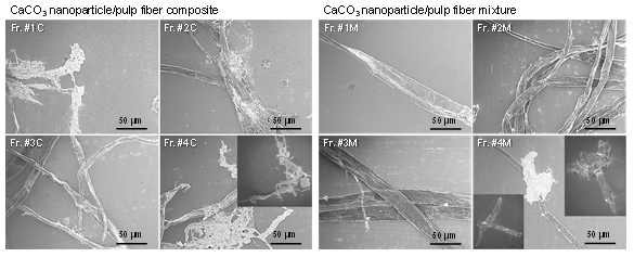
Fig. 5. The SEM images of fractions separated from the CaCO3/HBKP composite (Fr. #1C to Fr. #4C) and CaCO3/HBKP fiber mixture (Fr. #1M to Fr. #4M) by TFF
Dry Mass of Solid Components in Each Fraction
The dry masses of the solid components in each fraction were determined by filtration using filter paper and drying of the filtered residue (Fig. 6). The two slurries had similar mass distributions of solid components between the five fractions; the solid mass values were in the order of Fr. #4 > Fr. #3 > Fr. #5 > Fr. #2 > Fr. #1. The total masses of solid components from Fr. #1 to Fr. #5 for the CaCO3/HBKP composite and mixture slurries were 88.5 mg and 78.7 mg, respectively, which were lower than that of the solid components (125 mg) that were present originally in the slurries. This result indicated that part of the precipitated CaCO3 nanoparticles that was not attached to the HBKP long or short fibers filtered through the filter paper and was lost as filtrate.

Fig. 6. The dry masses of the solid components in each fraction separated from CaCO3/HBKP composite and mixture slurries by TFF
Because the mass of solid components in Fr. #4 for the composite slurry was higher than that for the mixture slurry, a higher amount of CaCO3 nanoparticles and/or HBKP short fibers was present in Fr. #4 for the composite slurry than for the mixture slurry. Although the absolute dry masses of Fr. #1 and Fr. #2 were low, the composite slurry had higher solid masses than the mixture slurry, which indicated that the CaCO3 nanoparticles attached stably to the HBKP fibers prepared with the ultrafine bubble method, and their presence in the composite slurry caused these results.
The dry solid mass in Fr. #3 for the composite slurry was slightly lower than that for the mixture slurry. This likely occurred because part of the HBKP fibers that were originally present in Fr. #3 aggregated with CaCO3 nanoparticles to move Fr. #1 or Fr. #2. Consequently, the dry solid masses in Frs. #1 and #2 for the composite slurry were higher than those for the mixture slurry. The dry solid mass in Fr. #5 for the composite slurry was lower than that for the mixture slurry, which probably occurred because CaCO3 nanoparticles that did not form aggregates with HBKP short fibers were present preferentially in this fraction of the mixture slurry.

Fig. 7. The CaCO3 contents of the solid components present in the fractions separated from CaCO3/HBKP fiber composite and mixture by TFF
CaCO3 Content of Composite and Mixture Components
The CaCO3 content of each fraction was determined via the standard incineration method (Fig. 7). The CaCO3 contents in Fr. #1 to Fr. #3 of the CaCO3/HBKP composite were more than twice those of the CaCO3/HBKP mixture. Therefore, the CaCO3 nanoparticles attached stably to the HBKP fibers when the ultrafine bubble method of the CO2 gas was used in composite sample preparation. The high CaCO3 contents of Fr. #1 to Fr. #3 in the composite slurry were consistent with those in Fig. 4; the fiber widths in the composite slurry were higher than those in the mixture slurry. The results in Fig. 7 were in accordance with those of the SEM images in Fig. 5; the CaCO3 nanoparticles attached stably to HBKP fiber surfaces in the CaCO3/HBKP composite.

Fig. 8. CaCO3 mass in each fraction calculated from results in Figs. 6 and 7
The masses of CaCO3 in each fraction were calculated from the results in Figs. 6 and 7, and they are shown in Fig. 8. Because most precipitated CaCO3 particle aggregates and short fiber/CaCO3 aggregates were present in Fr. #4, it had the highest mass of CaCO3. The masses of CaCO3 in Fr. #1 to Fr. #4 for the composite slurry were higher than those for the mixture slurry, which was consistent with the results in Fig. 4 and Fig. 5. The CaCO3 nanoparticles and their aggregates attached stably to HBKP long and short fibers in the composite slurry.
Versatile inorganic nanoparticle/pulp fiber composites can be prepared by the ultrafine bubble method, as shown in this study, at the industrial level for production of specialty papers with high values such as deodorant, anti-bacterial, flame-retardant, and X-ray shielding properties. The results obtained in this study showed that the TFF method is applicable to characterization of the inorganic nanoparticle/pulp fiber composites at the slurry stages in short times and to feedback of the obtained results to the production process.
CONCLUSIONS
- The CaCO3/HBKP composite or mixture slurry was separated into five fractions according to the hydrodynamic size of the components by TFF. The HBKP fiber aggregates, long and short fibers with or without aggregates of CaCO3 nanoparticles, and CaCO3 nanoparticles and their aggregates were adequately separated according to their hydrodynamic sizes by TFF under the selected conditions.
- The average fiber width in each fraction was measured from photographs using an image analyzer. Because the CaCO3 nanoparticles attached stably to the HBKP long and short fibers, the average fiber widths in Fr. #1 to Fr. #4 for the composite slurry were larger than those for the mixture slurry. This result was supported by the SEM images of each fraction; the HBKP long and short fibers in the composite slurry were present with aggregates of CaCO3 nanoparticles, whereas those in the mixture slurry were not.
- The TFF classification method can be used to precipitate CaCO3 nanoparticle/HBKP composite and mixture slurries for structural analyses of the components separated and present in each fraction.
ACKNOWLEDGEMENTS
The authors thank Mr. Kazuhiro Kurosu, Mr. Dai Nagahara, Mr. Susumu Kato, Mr. Masatoshi Oishi, Takuya Okawa of Nippon Paper Industries, and Dr. Keita Fuchise of the National Institute of Advanced Industrial Science and Technology (AIST) of Japan for their support.
REFERENCES CITED
El-Sherbiny, S., El-Sheikh, S. M., and Barhoum, A. (2015). “Preparation and modification of nano calcium carbonate filler from waste marble dust and commercial limestone for papermaking wet end application,” Powder Technol. 279, 290-300. DOI: 10.1016/j.powtec.2015.04.006
Fukuoka, M., Goto, S., and Ohtake, H. (2015a). “Novel analysis method for pulp furnish using tube flow fractionator (Part 1),” Japan TAPPI J. 69(4), 432-437. DOI: 10.2524/jtappij.69.432
Fukuoka, M., Suzuki, H., Nakatani, T., and Goto, S. (2015b). “Novel analysis method for pulp furnish using tube flow fractionator (Part 2),” Japan TAPPI J. 69(9), 987-993. DOI: 10.2524/jtappij.69.987
Fukuoka, M., Nakatani, T., and Goto, S. (2019). “Development of mineral hybrid fiber from calcium carbonate and pulp using fluid ― jet cavitation,” Japan TAPPI J. 73(11), 1103-1116. DOI: 10.2524/jtappij.73.1110
Fuchise-Fukuoka, M., Oishi, M., Goto, S., and Isogai, A. (2020). “Preparation of CaCO3 nanoparticle/pulp fiber composites with ultrafine bubbles,” Nord Pulp Pap. Res. J. 35, 279-287. DOI: 10.1515/npprj-2019-0078
Jagiello, L. A., Redlinger-Pohn, J. D., Fischer, W. J., Eckhart, R., and Bauer, W. (2016). “The effect of Dean flow in a tube flow fractionation device,” Nord. Pulp Pap. Res. J. 31(4), 642-647. DOI: 10.3183/NPPRJ-2016-31-04-p641-647
Jimoh, O. A., Ariffin, K. S., Hussin, H. B., and Temitope, A. E. (2018). “Synthesis of precipitated calcium carbonate: A review,” Carbonate Evaporite 33, 331-349. DOI: 10.1007/s13146-017-0341-x
JIS 8251 (2003). “Paper, board and pulps−Determination of residue (ash) on ignition at 525 degrees C,” Japanese Industrial Standard Committee, Tokyo, Japan.
Julkapli, N. M., and Bagheri, S. (2015). “Developments in nano-additives for paper industry,” J. Wood Sci. 62, 117-130. DOI: 10.1007/s10086-015-1532-5
Karinkanta, P., and Laitinen, O. (2017). “Use of tube flow fractionation in wood powder characterization,” Biomass Bioenerg. 99, 122-138. DOI: 10.1016/j.biombioe.2017.02.011
Kharisov, B. I., and Kharissova, O. V. (2010). “Advances in nanotechnology in paper processing,” Int. J. Green Nanotechnol: Mater. Sci. Eng. 2(1), M1-M8. DOI: 10.1080/19430841.2010.488204
Laitinen, O. (2011). Utilisation of Tube Flow Fractionation in Fibre and Particle Analysis, Doctoral Thesis, University of Oulu, Oulu, Finland.
Laitinen, O. T., Kemppainen, K., Stoor, T., and Niinimäki, J. (2011). “Fractionation of pulp and paper particles selectively by size,” BioResources 6(1), 672-685. DOI: 10.15376/biores.6.1.672-685
Nypelö, T., Pynnönen, H., Österberg, M., Paltakari, J., and Laine, J. (2012). “Interactions between inorganic nanoparticles and cellulose nanofibrils,” Cellulose 19, 779-792. DOI: 10.1007/s10570-012-9656-x
Techlab Systems (2019). “Bauer McNett fibre classifier,” (https://techlabsystems.com/en/datasheets/pulp/cf_bauer_mcnett_fibre_classifier.pdf), Accessed 10 April 2020.
Samyn, P., Barhoum, A., Öhlund, T., and Dufresne, A. (2017). “Review: Nanoparticles and nanostructured materials in papermaking,” J. Mater. Sci. 53, 146-184. DOI: 10.1007/s10853-017-1525-4
Shen, J., Song, Z., Qian, X., Yang, F., and Kong, F. (2010). “Nanofillers for papermaking wet end applications,” BioResources 5(3), 1328-1331. DOI: 10.15376/biores.5.3.1328-1331
Xia, C., Shi, S. Q., Cai, L., and Nasrazadani, S. (2015). “Increasing inorganic nanoparticle impregnation efficiency by external pressure for natural fibers,” Ind. Crop. Prod. 69, 395-399. DOI: 10.1016/j.indcrop.2015.02.054
Article submitted: April 12, 2020; Peer review completed: June 4, 2020; Revised version received: June 15, 2020; Accepted: July 23, 2020; Published: July 28, 2020.
DOI: 10.15376/biores.15.3.7048-7057