
Abstract
This work presents a study on the preparation of recycled wood fibre using different types of grinding equipment. It is also concerned with fibre preparation in an aerodynamic environment and describes the possibilities of using the material in various finished products. The authors used bio-rejects from the production of composite board materials, e.g. fibreboard and medium density fibreboard (MDF), in the form of lump scraps, as research material. In order to evaluate the efficiency of woodfibre waste recycling using various grinding equipment, the authors analysed the qualitative characteristics of the resulting semi-finished woodfibre materials and mathematically calculated the primary technological and design parameters of the grinders. The results of the study provide a scientific basis for the efficiency of a fundamentally new recycled wood fibre dry preparation method and system.
Download PDF
Full Article
Using Various Grinding Equipment for the Preparation of Recycled Wood Fibre
Venera Matygulina,a,* Natalya Chistova,a,b and Roman Marchenko a
This work presents a study on the preparation of recycled wood fibre using different types of grinding equipment. It is also concerned with fibre preparation in an aerodynamic environment and describes the possibilities of using the material in various finished products. The authors used bio-rejects from the production of composite board materials, e.g. fibreboard and medium density fibreboard (MDF), in the form of lump scraps, as research material. In order to evaluate the efficiency of woodfibre waste recycling using various grinding equipment, the authors analysed the qualitative characteristics of the resulting semi-finished woodfibre materials and mathematically calculated the primary technological and design parameters of the grinders. The results of the study provide a scientific basis for the efficiency of a fundamentally new recycled wood fibre dry preparation method and system.
Keywords: Woodfibre wastes; Grinding; Defibration; Fibrillation; Aerodynamic environment;
Semi-finished woodfibre materials
Contact information: a: Reshetnev Siberian State University of Science and Technology 31, Krasnoyarskii Rabochii Prospect, Krasnoyarsk 660000 Russian Federation; b: Rail Transport Institute Branch of IrGUPS, 2g, Novaya Zarya Street, Krasnoyarsk 660028 Russian Federation;
* Corresponding author: caress-lsib@rambler.ru
INTRODUCTION
The current problem of saving resources and improving the quality of finished wood products has received substantial attention, which is confirmed by the numerous studies attempting to find alternative solutions and conditions for widespread usage of different types of wood waste and low-quality products in various industries. It is obvious that the industry-specific problem of the preparation of secondary semi-finished woodfibre materials requires further scientific research; this would require proposing a fundamentally new method and system for woodfibre waste recycling, as well as finding further uses for the recycled fibreboard waste in finished products (Chistova and Matygulina 2007; Matygulina 2007; Chistova 2010; Zhang et al. 2015; Chistova and Morozov 2015; Ihnát et al. 2017; Przybysz et al. 2020).
Annually, a large volume of board product waste is generated, which contains semi-finished wood fibre. Such waste includes not only lumpy waste obtained as a result of cutting and trimming the edges of the boards during fiberboard production, but also used furniture and construction waste. The possibility of processing such waste, as well as their involvement in primary production process, has been considered by many authors (Nicewicz and Leszek 2010; Wan et al. 2014; Morozov 2016; Moezipour et al. 2017). In the pulp and paper industry, scientists have also extensively researched the issue of recycling cellulose fibres for paper production (Ackermann et al. 2000; Hubbe et al. 2007).
It is commonly known that the recycling of woodfibre wastes from various origins has a decisive effect on the quality of the resulting semi-finished woodfibre material (Benthien et al. 2014, 2017). Depending on the processing method and the type of secondary semi-finished materials, various types of cutting and non-cutting equipment are currently used to recycle woodfibre wastes. This equipment is used to grind fibers and impart various properties to the wood fibre mass, which provides further bonding in the finished product. In comparison to cutting machines, non-cutting equipment provides softer and gentler processing; however, it is more energy-intensive and produces a limited number of semi-finished woodfibre materials.
The purpose of this research is to evaluate the efficiency of woodfibre waste recycling using various grinders and provide a scientific basis for the feasibility of using secondary semi-finished woodfibre materials prepared via the dry grinding method.
MATERIALS AND METHODS
The authors used bio-rejects from the production of composite board products, e.g., fibreboard and medium-density fibreboard (MDF), in the form of lump scraps (cuttings and patches), as research material.
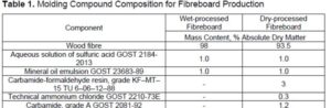
Wet-processed fibreboards were obtained without using a binding material, and they were composed only of an aqueous solution of sulfuric acid and a mineral oil emulsion. When producing medium-density fibreboards (MDF), carbamide-formaldehyde resin, sulfuric acid, ammonium chloride, carbamide, and mineral oil were added to the fibre in an amount corresponding to the state standard. Table 1 shows the molding compound composition for fibreboard production.
Heat-treated at high temperatures and pressures, the woodfibre wastes represented so-called “inactivated” fibres that are unable (when reprocessed in high-speed cutting mills) to reform strong interfibre bonds in the resulting finished product due to the so-called “irreversible hornification”.
To evaluate the efficiency of plant waste recycling, the authors considered various types of grinding equipment: disk crusher, conical mill, pulper (using water and steam), and dry grinding machine. All other conditions were equal when evaluating the efficiency of the preparation methods.
A high-speed disc crusher (a disk refiner) grinds material between the rotor cutters and the stator grinding tool. During the grinding process in such disk crushers, the initial woodfibre suspension is subject to compression and friction forces. The compression force causes the absorption of energy and leads to the weakening of interfibre bonds. A gap between the cutters determines compression force; its nature is determined by the structure of a grinding tool. Friction force is determined by the segment material and the degree of segment wear (Laskeev 1967). A disk refiner RR-50 was employed (capacity 50 ton/day, grinding disk clearance 0.05 to 0.15 *10-3 m, outboard auger rotational speed 12 to 15.4 min-1, disk diameter 1000 mm). The second grinding machine under study was a conical mill with a cast steel. This machine grinds material under pressure and has one pair of joint conical grinding parts (rotor and stator). A conical mill grinds a low concentration of plant fibre as it passes through the rotor and stator cutters due to hydraulic pressure and an increasing centrifugal force created by an increase in the diameter of a grinding compartment. A conical mill MK-1 (capacity 4 to 16 ton/day, mass concentration 2 to 4%). The third grinding machine was a semi-industrial pulper with combined fibre processing (cutting and non-cutting grinding). This machine differs from other types of non-cutting equipment, e.g., jet-barrier, cavitation and inertial grinding, etc., by having higher performance, lower power consumption per unit produced, lower requirements for production area, lower equipment maintenance costs, lower machine price, and simpler operation. It can be described as a semi-industrial pulper (secondary fibre treatment 6*102 to 24*102 s, secondary mass temperature 10 to 50 °C, and secondary mass concentration 1 to 3%).
In all of the above machines, the grinding is carried out under the presence of water, steam, high temperature, and pressure.
This study also included a semi-industrial grinding machine, i.e., an MR-4 rotary cutting mill that grinds in an air environment. Since the design features and technology of semi-finished woodfibre material preparation via cutting grinders are commonly known, a description of the dry grinding machine will be presented below. Figure 1 and Table 2 show the general appearance and technical specifications of the rotary cutting mill (Chistova et al. 2015а, Morozov 2016).
As shown in Fig. 1, a MR-4 machine utilized for the dry grinding and recycling of woodfibre wastes consists of a housing, which encompasses a shaft (4) with attached rotor cutters (1) in a chequerwise arrangement.
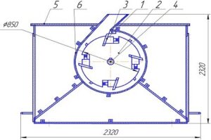
Fig. 1. General appearance of the MR-4 laboratory rotary cutting mill (1 – rotor cutters; 2 – pivot; 3 – stator cutter (cutting anvil); 4 – shaft; 5 – machine housing; and 6 – separator)
The stator cutter (3) that has two bevel angles is attached to the side covers of the housing with adjustable holding devices. The separator (6) is installed inside the housing along the cylinder generatrix to defibrate secondary wood fibres after grinding. The separator regulates the grinding time, i.e., the time the wood fibre is kept in the grinding area, between the rotor and the separator. The separator is a perforated metal mesh with different mesh sizes. It serves as a sorting device for the ground fibre by fractions.
To evaluate the efficiency of plant waste recycling using various types of grinding equipment, the authors estimated the qualitative characteristics of the resulting semi-finished woodfibre material and mathematically calculated the primary technological and design parameters of the grinders (Borovikov and Borovikov 1998; Pizhurin and Pizhurin 2005; Riegler et al. 2013). The calculations and evaluation of the primary technological and design parameters of the grinding tools were carried out using the Matlab software package (version 6.13) and the “Calculation of cutting steel process parameters” program by Nabieva et al. 2009).
RESULTS AND DISCUSSION
A study by Chistova (2010) revealed that due to the hydrodynamic processing of woodfibre wastes, all types of grinders generated a considerable number of tiny fibers and fines in the resulting mass, e.g., fine pulp, group A flour, and group B fibril plasma. The fines in the composite material primarily fill the space between the wood fibres of the primary fractions that form the structure of the finished products. However, the generation of the considerable number of fines complicates the dehydration of the woodfibre mat and negatively affects some of the strength properties of the finished composite materials (Ferritsius et al. 2018).
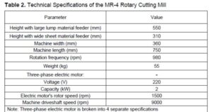
As an advantage of the proposed machine (in comparison with those described earlier), which prepares semi-finished woodfibre materials via the dry method, it can be noted that this grinder can produce secondary semi-finished woodfibre materials in the absence of high temperatures and pressure, without chemical additives, steam, and water. Processing the secondary mass in a rotary cutting mill enables the material to be defibrated into individual fibres without major damage. When processing secondary fibres in a conical mill, as well as in a disk crusher, the average fibre length decreases, due to repeated work of the steel. In addition, when compared with the indicators of the secondary mass processed in a rotary cutting mill, the amount of group A fibril plasma and group B flour drastically increases for the same reason. Table 3 shows the influence of various types of grinding equipment on the qualitative characteristics of the resulting secondary wood fibres in terms of fine fractions and fines.
The grinding quality fractional index was determined on a FVG-2 fractionator used for fractionation – fibre separation by size (sieves with hole diameters of 1.0; 0.63; 0.4; 0,315; 0.2; 0.16 mm). After fractionation, the fibre from each sieve was weighed separately. The weight of each fraction was expressed as a percentage of the total weighted sample. The fractional index was determined according to Eq. 1,
where mg is the group fibre mass (g), and mn is the total sample mass (g).
The fractional grinding index expressed in grams shows how much the initial mass would weigh if it consisted of the same quantity of fibres of the smallest fraction. That is, the higher the grinding index is, the higher the mass content of medium and fine fractions is in the fibreboard mass.
One of the most important indices characterising inter-fibre bonding is the specific fibre surface area S. To determine this surface area, the mean length and mean diameter of fibres from each sieve were estimated per fraction. To estimate them, a curvimeter and an LV–34 digital microscope with a dividing ruler and with 100 to 1500 times maximum magnification were used. The fibres were then determined and sorted according to their fractions.
Based on the calculated mean length and mean diameter, the specific fibre surface area S was determined according to Eq. 2,
where ρ is the specific fibre weight (g/cm3), La is the mean fibre length (μm), and Da is the mean fibre diameter (μm).
The secondary fibreboard appearance was assessed using an LV-18 electronic microscope with 2 to 4-times magnification and a ScopoTek DCM310 camera inserted into the microscope eyepiece. The mass under study (1 g of absolute dry matter) was evenly distributed on the microscope stage and photographed with the ScopoTek DCM310 camera.
By analysing Table 3, it can be noted that the secondary woodfibre material produced via the dry grinding method had the highest quality wood fibres in terms of dimensional and qualitative characteristics. In contrast to cellulose fibres, the quality of which is characterised by the inner-to-outer diameter ratio, the quality of wood fibres is characterised by their specific surface area, i.e. their fibre-length-to-diameter ratio. The higher this indicator is, the higher the fibre bonding rates are in finished products.
Figure 2 shows the secondary wood fibres produced from fibreboard wastes prepared via a classic technique in a hydrodynamic environment at high temperatures and pressure. Figure 3 shows the wood fibres prepared in an aerodynamic environment via a MR-4 rotary cutting machine.
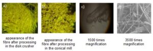
Fig. 2. Secondary wood fibres prepared via a classic technique in a hydrodynamic environment at high temperatures and pressure
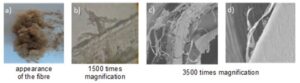
Fig. 3. Secondary wood fibres prepared in an aerodynamic environment via a MR-4 rotary cutting machine
As can be seen from Figs. 2 and 3, preparation of the semi-finished woodfibre materials, regardless of the grinding machine used, showed some signs of fibre hornification. However, when recycling woodfibre waste in a rotary cutting mill, along with the hornification, the “inactivated” fibre also showed signs of internal fibrillation. In the author’s opinion, this can be explained by the technological and design features of the rotary cutting mill, which has been confirmed via theoretical and experimental research (Chistova and Morozov 2015; Morozov 2016).
One of the primary design parameters of the grinding tools that characterises the efficiency of its performance is the number of simultaneously moving intersection points of the rotor cutters and the stator cutter (t), which forms the value of the second cutting length. Thus, in disk crushers, each intersection point of the rotor and stator cutter forms a grinding surface in the form of a rhombus (Nabieva et al. 2009).
In order to determine the number of intersection points of the cutting edges of the rotor cutters and the stator cutter using a rotary cutting mill when defibrating plant waste via dry grinding, a transparent graphic model of the rotor and stator was made in compliance with the real geometric dimensions (as shown in Fig. 4) using the KOMPAS-3DV12 software package (V12, Аscon, Saint-Petersburg, Russian Federation).
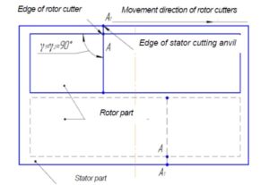
Fig. 4. Graphic model of the rotor and stator (flat drawing)
It can be seen from the diagram shown in Fig. 4 that the mill design allows the intersection of the cutting surfaces to form along the entire length of the stator. The angles of the cutting edges (γ1) in the profile of the rotor cutters are equal to the inclination angles of the edges of the rotor cutters (γ2), which is 90°. As a result, the intersection point of the cutting edges forms a line directed along the plane of the cutters.
The parameters were calculated with respect to the given rotor speed, the cutter width, the installation angles of the cutters to the generatrix of the singular tooling sector, the inner and outer radii of the working zone cylinder, the tool design, and the number of sectors on the grinding tool.
Additional primary design parameters of the grinding tool, which characterise the efficiency of its use, include the second cutting length (Ls) and the cyclic elementary length (Lω.el.).
The second cutting length
The second cutting length of the steel allows for the estimation of the total contact length of the intersection of the cutting edges of the rotor cutters with the stator cutter formed in one second in the gap between the stator and the rotor. In addition, the Ls characterises the number of simultaneously processed fibres, as calculated according to Eq. 3,
![]()
where is the number of stator cutters (1), is the number of rotor cutters (8), is the cutter length on the cylinder (0.25 m), and is the rotor speed (980 rpm).
As can be seen from Eq. 3, the second cutting length, which depends on the design features of the grinding elements of the machine, has a major effect on the dimensional, qualitative, and morphological characteristics of the secondary wood fibre. In a study by Smith (1922), a relationship between a fibre shortening effect and an increased second cutting length was established.
Cyclic elementary length
The cyclic elementary length characterises the average fibre length “cut off” by a pair of cutters (cutter and cutting anvil) after one revolution of the rotor relative to the stator (separator). This parameter evaluates the efficiency of the grinding process in terms of fibre shortening or obtaining a long-fiber fraction with the presence of fibrillation, as shown in Eq. 4,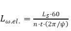
where t is the number of moving intersection points of the rotor cutters relative to the stator cutters within one sector, n is the rotor speed (rpm), and 2π/ψ is the number of sectors.
According to the results of the mathematical calculation of the primary technological and design parameters of the grinding tools for the rotary cutting mill under study, the second cutting length was 32.6 m/s, and the cyclic elementary length was 0.5 m (provided that the simultaneously moving intersection points of the rotor cutters with the stator cutter were equal to 1).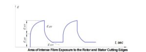
Fig. 5. Diagram of the secondary semi-finished woodfibre material defibration within a singular sector of the grinding compartment (εel is the elastic deformation and εres is the residual deformation)
In order to confirm the phenomena and processes of plant waste preparation that take place in the MR-4 grinding compartment, a diagram showing the defibrating process for secondary semi-finished woodfibre material within a single sector of the grinding compartment was generated. The calculation diagram of the distribution of the forces arising during the grinding process are presented in Fig. 5; a stress diagram arising from the interaction of the rotor and stator cutters as well as a diagram of the crossing angles when installed on the machine were generated.
In order to provide a better explanation of the woodfibre material destruction process as a result of dry grinding, Fig. 5 shows a diagram displaying the woodfibre grinding process within a single sector of the grinding compartment. A single sector represents the zone of the grinding compartment bound by the first pivot rotor cutter and the area up to the first edge of the second pivot rotor cutter. Figure 5 shows that wood fibre deformation occurs when the rotor cutter intersects with the stator cutter (when stress occurs at the initial time).
The total deformation of the secondary semi-finished wood material in a singular sector of the machine grinding compartment will include the following changes: elastic deformation due to changes in the bond angles and the distance between chemically bonded atomic centres; and residual deformation that reflects the irreversible movement of the centres of gravity of the molecules and supramolecular structures (in the fibre).
After the rotor cutter passes over the stator cutter (cutting anvil), the stress values sharply decrease, while residual deformation remains. After the stress between the stator and the rotor is relieved, some reversed elastic aftereffects appear in the fibre; a rapid decrease in deformation corresponds to the εel value. The irreversible part of the deformation (εres) does not decompress and remains unchanged. When the fibreboard material falls under the influence of the subsequent rotor cutter, the full stress-relieve cycle is repeated. After the wood fibre enters the area between the stator cutters, the mixing and trampling of the fibers, as well as being subjected to friction occurs, which is accompanied by aerodynamic phenomena with a high concentration of secondary wood fibre in the grinding zone.
When wood material enters the next singular sector of the grinding compartment, the exposure cycle of the grinding elements on the secondary woodfibre material is repeated. With the repeated passage of the wood material through the sectors of the grinding compartment, the fibre accumulates residual stresses, which leads to complete separation of the patches into secondary wood fibres. When ground in a mill, reversible mechanical deformations of relaxed nature ensure the complete separation of the fibre bundles into individual fibres, as well as ensuring their fibrillation.
In order to determine the primary factors that establish the common factors of grinding efficiency, a calculation diagram of the distribution of the forces arising from the woodfibre waste defibration process in the machine was generated (Fig. 6). As previously mentioned, the results of defibrating, cutting, trampling, compressing, and shear forces prevail, which determine various parameters, i.e., the magnitude of the shear stress of grinding, the specific load on the cutter edge, the maximum specific pressure acting in the grinding gap, and the second cutting and cyclic elementary length.
The magnitude of the tangential grinding stress (δ) will coincide with the tangential component of the support reaction and will be determined by Eq. 5,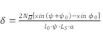

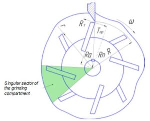
Fig. 6. Calculation diagram of the distribution of forces arising from grinding (Тfr is the force of friction on the plane of the stator cutter (N); Rn is the normal component of the support reaction (N); Rτ is the tangential component of the support reaction (N); RА is the reaction force of the support (N); and ω is the angular speed (s-1)
The useful grinding power is defined as the difference between the total power consumed by the mill at a given grinding mode and the idle power when the grinding machine operates with separated cutting disks (Goncharov 1990).
The second factor that determines the course of the grinding process, which is a measurement of the intensity of the impact on the fibre (Goncharov 1990; Leonovich 2003), is the specific load on the cutter edge (BS), which is determined by Eq. 6,
where LS is the second cutting length (m), and NU is the useful power (kW).
As can be seen from Eqs. 5 and 6, when compared to the specific load on the cutter edge, the tangential grinding stress more fully reflects the relationship between the geometric parameters of the grinding elements and the exposure intensity on the fibres, which was confirmed by the results of further experimental research.
The distribution analysis of the forces on the rotor cutter surface during the grinding process formed a basis for a variation diagram of the force that compresses the wood fibres in the grinding gap (Fig. 7). The diagram was drawn with respect to a singular sector under consideration, which, according to the authors, more thoroughly explains the nature of impact of the rotor cutters and the stator cutter on the woodfibre material.
As can be seen in Fig. 7, when the rotor cutter meets the stator cutter (area I), the impact on the fibre sharply increases within the maximum pressure zone. With further passage of the rotor cutter along the stator cutter, the impact of the grinding elements on the fibre sharply decreases (area II) within the zone of falling pressures. In the area of low pressures, i.e., in the mesh between the cutters (section III), there are practically no impact forces.
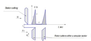
Fig. 7. Diagram of the stresses arising from the interaction of the rotor cutters and the stator cutter (Vr is the speed vector direction of rotor cutters, and z is the grinding gap (mm))
The maximum specific pressure in the gap between the rotor cutter and the stator cutter () was determined according to Eq. 7,
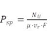
where NU is the useful grinding power (kW), μ is the grinding factor, vr is the peripheral rotor speed (m/s), and F is the contact area of the rotor cutters and the stator cutters (m2) (Goncharov 1990).
The peripheral rotor speed (vr) (m/s) is determined by Eq. 8,
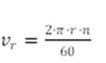
where n is the rotor revolution speed (rpm), and r is the rotor radius (m).
By substituting numerical values into the above formulas, the authors obtained the maximum pressure in the grinding gap for the grinding tooling used in this work (equal to 0.73 MPa).
Thus, by varying the calculated values of the specific load on the edges of the cutter and the tangential stress, it is possible to design various types of grinding tools for various types of woodfibre materials. Thus, with a decrease in the width of the rotor cutter at a value of а is greater than l0 when NU is constant, both factors (BS and δ) decrease. With a further decrease in the width of the rotor cutter (а is less than l0), the specific load on its edge will decrease, with the tangential grinding stress contrarily increasing when а is less than l0. With the same values of mill productivity and useful grinding power, equal specific loads on the rotor cutter edge can be obtained with the same values of the rotor cutter tooling pitch. In this case, the specific load on the edges of the rotor cutters and the specific consumption of useful energy will be identical, but the tangential stresses will be different. By changing the geometric characteristics of the rotor cutter, it is possible to achieve equal values of the specific load on the edge of the rotor cutter and different values of the tangential stress.
The theoretical evaluation of the MR-4 grinding machine technological and design parameters showed that the residual shear forces and tangential stresses that arise as a result of elastic and permanent deformation in the fibre have the greatest influence on the recycling of woodfibre waste.
CONCLUSIONS
- The research output shows that secondary woodfibre materials produced via the dry method has the best indicators for the dimensional and qualitative characteristics as well as the physical and mechanical properties in terms of the finished product. This study included a comparative efficiency analysis of the plant waste recycling methods using various types of grinding equipment: a high-speed disk crusher, a conical mill, a pulper, and a dry grinding machine. The technological and design parameters of the grinders were evaluated.
- The disadvantages of the grinding equipment operating in a hydrodynamic environment were found to include the following: the impossibility of producing fibrillated secondary fibres capable of forming bonds in the finished product; considerable energy consumption for the production of secondary wood fibres; production of a limited number of semi-finished woodfibre materials; and the need for the preliminary grinding, soaking, pumping into a mass pool, , of the waste material. An analysis of the dimensional and qualitative characteristics of woodfibre waste processed in a hydrodynamic environment showed that the fibre had signs of hornification and a substantial decrease in the fractional indicator of grinding quality, as well as the fibrillation of the fibres being almost entirely absent. Therefore, such fibres cannot form cohesive and adhesive bonds in the finished products.
- While it is completely justified to use the cutting grinders for the production of initial fibre material, according to the authors, they are inappropriate for the production of secondary semi-finished woodfibre materials. This is due to the fact that the previously processed wood fibres repeatedly undergo additional cutting in the working elements of the cutting machines, which does not allow full utilization of the secondary raw materials.
- During this study, it was found that it is preferable to prepare secondary semi-finished woodfibre materials via the dry method, and a MP-4 rotary cutting mill would be a suitable choice. Based on the results of the mathematical calculation of the primary technological and design parameters of the grinding tool for the rotary cutting mill, the number of intersection points were determined, and the second cutting length and the cyclic elementary length were calculated.
- The preparation of secondary semi-finished fibreboard materials in a grinding machine operating as per the dry grinding method can be nominally divided into two zones: I – mechanical effect on fibreboard wastes and their separation by cutting, crumpling, flattening between the rotor and stator cutters; II – defibration, crumpling, breaking and fibrillation of secondary wood fibres in the space between the rotor cutters and the separator surface, accompanied by aerodynamic processes. In the future, it is planned to study the physical phenomena, processes, and regularities of secondary fibreboard material preparation in an aerodynamic environment without using water, steam, high temperatures, or pressure.
ACKNOWLEDGEMENTS
The authors express their gratitude to the Centre for Collective Use of KSC SB RAS for supporting their research. This work was carried out under the State Assignment issued by the Ministry of Education and Science of Russia for the project: “Technology and Equipment for the Plant Biomass Chemical Processing” by the Plant Material Deep Conversion Laboratory (Subject No. FEFE-2020-0016).
REFERENCES CITED
Ackermann, K., Götsching L., and Pakarinen H. (2000). “The potential of recycled fiber in papermaking” in: Recycled Fiber and Deinking, L. Göttsching, and H. Pakarinen (ed.), Fapet Oy, Helsinki, Finland, pp. 358-438.
Benthien, J., Heldner S., and Ohlmeyer M. (2017). “Investigation of the interrelations between defibration conditions, fiber size and medium-density fiberboard (MDF) properties,” European Journal of Wood and Wood Products 75, 215-232. DOI: 10.1007/s00107-016-1094-2
Benthien, J. T., Bähnisch, C., Heldner, S., and Ohlmeyer, M. (2014). “Effect of fiber size distribution on medium-density fiberboard properties caused by varied steaming time and temperature of defibration process,” Wood and Fiber Science 46(2), 175-185.
Borovikov, V. P., and Borovikov, I. P. (1998). STATISTICA. Statistical Analysis and Data Processing in Windows, Filin Inf.-Publ. House, Moscow, Russia.
Chistova, N. G. (2009). “Fiberboard production by dry method,” Chemistry of Plant Materials 2009(2), 141-144.
Chistova, N. G. (2010). Recycling Wood Waste in Fiberboard Production, Ph.D. Dissertation, Siberian State Тechnological University, Krasnoyarsk, Russia.
Chistova, N. G., and Matygulina, V. N. (2007). “Influence of grinding modes on the quality of wood fiber for fiberboard production,” Bulletin of KrasSAU 2007(4), 139-143.
Chistova, N. G., and Morozov, I. M. (2015). “Influence of technological parameters of the grinding machine on the properties of wood pulp and finished fiberboard,” Chemistry of Plant Materials 2015(3), 185-191.
Chistova, N. G., Morozov, I. M., Yakimov, V. A., Alashkevich, Y. D., and Zyryanov, M. A. (2015a). “Fiberboard production by the dry method with the use of wood waste generated by panel sizing machines,” Chemistry of Plant Materials 2015(4), 119-124.
Chistova, N. G., Zyryanov, M. A., Rubinskaya, A. V., and Lyatt, M. S. (2014). “Grinding set of stator,” Utility Model Patent No. 143379.
Chistova, N. G., Vititnev, A. Y., Alashkevich, Y. D., Zyryanov, M. A., and Kozhevnikov A.K. (2015b). “Grinding set of a disk mill,” Utility Model Patent No. 160973.
Ferritsius, O., Ferritsius, R., and Rundlöf, M. (2018). “Average fiber length as a measure of the amount of long fibers in mechanical pulps – Ranking of pulps may shift,” Nordic Pulp & Paper Research Journal 33(3), 468-481. DOI: 10.1515/npprj-2018-3058
Goncharov, V. N. (1990). Theoretical Basics of Grinding Fibrous Materials in Cutting Machines, Ph.D. Dissertation, School, City, Country. Leningrad Technological Institute of Pulp and Paper Industry, Leningrad, Union of Soviet Socialist Republics.
Hubbe, M. A., Venditti, R. A., and Rojas, O. J. (2007). “What happens to cellulosic fibers during papermaking and recycling? A review,” BioResources 2(4), 739-788. DOI: 10.15376/biores.2.4.739-788
Ihnát, V., Lübke H., Russ A., and Borůvka, V. (2017). “Waste agglomerated wood materials as a secondary raw material for chipboards and fiberboards. Part I. Preparation and characterization of wood chips in terms of their reuse,” Wood Research 62(1), 45-56.
Laskeev, P. K. (1967). Wood Pulp Production, Lesnaya Promyshlennost, Moscow, Russia.
Leonovich, A. A. (2003). Physical and Chemical Bases of the Formation of Wood-Based Boards, Khimizdat, St. Petersburg, Russia.
Matygulina, V. N. (2007). Preparation of Wood Fiber for Fiberboard Production by Dry Method, Ph.D. Dissertation, Siberian State Тechnological University, Krasnoyarsk, Russia.
McDonald, D., Ouellet, D., Tchepel, M., Wild, P., Provan, J., and Jeffrey, D. (2014). “Wood mechanics: From chips to flocs to fibers – Part I,” Journal of Science & Techology for Forest Products and Processes 4(5), 23-30.
Moezzipour, B., Ahmadi, M., Abdolkhani, A., and Doosthoseini, K. (2017). “Chemical changes of wood fibers after hydrothermal recycling of MDF wastes,” Journal of the Indian Academy of Wood Science 14, 133-138. DOI: 10.1007/s13196-017-0198-6
Morozov, I. M. (2016). Preparation and Use of Fiberboard Waste in the Production of Fiberboard, Ph.D. Dissertation, Siberian State Тechnological University, Krasnoyarsk, Russia.
Nabieva, A. A, Nesterov, E. E., Alashkevich, Y. D., and Karpenko, D. S. (2009). Numerical Method for Determining the Second Cutting Length of a Sector Knife Set of Disk Mills with Parallel Rectilinear Blades of Constant Width (Certificate No. 2009613683 RF/. – No. 2009612514), Publisher, City, County. Siberian State Тechnological University, Krasnoyarsk, Russia.
Nicewicz, D., and Leszek, D. (2010). “Recycling of insulation boards by reuse,” Annals of Warsaw University of Life Sciences – SGGW Forest and Wood Technology 72, 57-61.
Pizhurin, A. A., and Pizhurin, A. A. (2005). Scientific Research Foundations, MGUL Moscow State University of Forestry, Moscow, Russia.
Przybysz, P., Dubowik, M., Małachowska, E., Kucner, M., Gajadhur, M., and Przybysz, K. (2020). “Effect of refining intensity on the progress of internal fibrillation and shortening of cellulose fibers,” BioResources 15(1), 1482-1499. DOI: 10.15376/biores.15.1.1482-1499
Riegler, M., Spangl, B., Weigl, M., Wimmer, R., and Muller, U. (2013). “Simulation of a real-time process adaptation in the manufacture of high-density fiberboards using multivariate regression analysis and feedforward control,” Wood Science and Technology 47, 1243-1259. DOI: 10.1007/s00226-013-0571-6
Smith, S. (1922). Die rationelle Theorie das Ganzzeughollandar. Otto Ernst Verlag. Teil I, Publisher, Berlin, Germany.
Wan, H., Wang, X.-M., Barry, A., and Shen, J. (2014). “Recycling wood composite panels: Characterizing recycled materials,” BioResources 9(4), 7554-7565. DOI: 10.15376/biores.9.4.7554-7565
Zhang, D., Zhang, A., and Xue, L. (2015). “A review of preparation of binderless fiberboards and its self-bonding mechanism,” Wood Science and Technology 49, 661-679. DOI: 10.1007/s00226-015-0728-6
Article submitted: November 26, 2020; Peer review completed: January 10, 2021; Revised version received: February 3, 2021; Accepted: February 4, 2021; Published: February 9, 2021.
DOI: 10.15376/biores.16.2.2433-2447