
Abstract
Unsatisfactory macroscopic strength is one of the important reasons that limit the application of cellulose composites. However, the mechanical properties of cellulose composites could be improved by the directional orientation of cellulose nanofibers. In this paper, a five-channel microfluidic chip was designed to fabricate core-sheath cellulose nanocrystal/ cationic polyacrylamide (CNC/CPAM) composite filament. The core spinning solution with high flow velocity promoted the extended arrangement of CPAM in sheath flow. CPAM with long chain structure could not only reduce the electrostatic repulsion between CNCs, but also ensures the fiber orientation by inhibiting the disorderly diffusion of CNCs, thus improving the toughness of the composite filament. The orientation of the composite fiber was studied by wide-angle X-ray scattering, showing an orientation index of 0.725. The mechanical properties of the composite fiber were tested by a universal material testing machine. The tensile strength was 510 ± 20 MPa, which was about 117% higher than that of pure CNC spun fiber, and the elongation at break was also increased by about 70%. The improvement in mechanical properties was attributed to the increase in the content of intramolecular and intermolecular hydrogen bonds. In addition, the demonstrated spinning technology provided a new way for preparing high-performance composite fibers.
Download PDF
Full Article
Aligned Cellulose Nanocrystal Composite Filament with High Tensile Strength Enhanced by Cationic Polyacrylamide via Flow Focusing Approach
Yuda Wang,a Pinle Zhang,a Jinge Guo,a Ziyi Zhong,a Wei Li,a,b and Xinliang Liu a,b,*
Unsatisfactory macroscopic strength is one of the important reasons that limit the application of cellulose composites. However, the mechanical properties of cellulose composites could be improved by the directional orientation of cellulose nanofibers. In this paper, a five-channel microfluidic chip was designed to fabricate core-sheath cellulose nanocrystal/ cationic polyacrylamide (CNC/CPAM) composite filament. The core spinning solution with high flow velocity promoted the extended arrangement of CPAM in sheath flow. CPAM with long chain structure could not only reduce the electrostatic repulsion between CNCs, but also ensures the fiber orientation by inhibiting the disorderly diffusion of CNCs, thus improving the toughness of the composite filament. The orientation of the composite fiber was studied by wide-angle X-ray scattering, showing an orientation index of 0.725. The mechanical properties of the composite fiber were tested by a universal material testing machine. The tensile strength was 510 ± 20 MPa, which was about 117% higher than that of pure CNC spun fiber, and the elongation at break was also increased by about 70%. The improvement in mechanical properties was attributed to the increase in the content of intramolecular and intermolecular hydrogen bonds. In addition, the demonstrated spinning technology provided a new way for preparing high-performance composite fibers.
DOI: 10.15376/biores.18.3.5813-5837
Keywords: Cellulose nanocrystals; Polyacrylamide; Orientation; Microfluidic spinning
Contact information: a: College of Light Industry and Food Engineering, Guangxi University, Nanning 530004, P. R. China; b: Guangxi Key Laboratory of Clean Pulp and Papermaking and Pollution Control, Guangxi University, Nanning 530004, P. R. China; *Corresponding author: xinliang.liu@hotmail.com
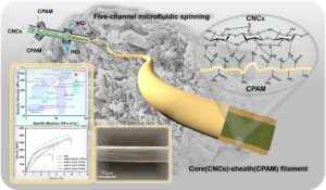
GRAPHICAL ABSTRACT
INTRODUCTION
Cellulose, the most abundant natural resource on the earth, has many advantages, including renewability, low cost, biocompatibility, and good mechanical properties (Xue et al. 2021; Tahir et al. 2022). Cellulose has been widely used, such as in gas separation (Mubashir et al. 2021), medicine (Jiang et al. 2019), reinforcing material (Aziz et al. 2023), etc., and such applications have led to further development of cellulose-based materials. However, in order to obtain better properties of cellulose-based materials, often it is necessary to remove hemicellulose and lignin or to get micro- and nanostructures of cellulose fiber from cellulosic biomass (Gundupalli et al. 2023). Most cellulosic materials typically exhibit anisotropic mechanical properties and are characterized by an ordered orientation of the cellulose fibers, which gives these cellulosic materials a high ultimate strength as well as stiffness (Wegst et al. 2015; Jakob et al. 2022). Cellulose nanocrystals (CNCs) are kinds of nano-scale long rod-shaped crystals. These are obtained by centrifugal screening of the particles left over after acid hydrolysis of the amorphous region of natural cellulose (Raza and Abu-Jdayil 2022). CNCs are usually prepared from cellulose fibers by acid hydrolysis (Tahir et al. 2022). CNCs offer many advantages such as high tensile strength (7.5 to 7.7 GPa), elastic modulus (110 to 220 and 10 to 50 GPa in axial and transverse directions, respectively) and low weight density (1.6 g/cm3) (Yang et al. 2013). The orderly arrangement of CNCs not only can bring about some anisotropic properties, but it also can enhance the mechanical properties of composites (Shrestha et al. 2018; Babaei-Ghazvini et al. 2020; Li et al. 2021a; Wang et al. 2022). But for the moment, CNCs are generally considered as enhancers for nanocomposites rather than main material for potent eco-friendly composites (Vatansever et al. 2020; Chen et al. 2021).
High-orientation CNCs fiber filaments have potential applications on protective textiles, special packaging or auxiliary materials for the aviation sector due to their low density and high mechanical strength. However, it is difficult to arrange and assemble CNCs in an orderly manner to form a macroscopic dense structure because the large electrostatic repulsion among them (Håkansson et al. 2014). Therefore, it is challenging to prepare cellulose long fibers with CNCs without sacrificing their high mechanical properties.
There are multiple methods to reassemble nanocellulose to prepare filaments with excellent mechanical properties (Rosen et al. 2021; Lundahl et al. 2016), such as dry spinning, wet spinning, interfacial complexing spinning, and electrospinning. For traditional dry/wet spinning, although the tensile strength and orientation of the filament can be improved by increasing the spinning rate and increasing the stretch ratio, the orientation only increases from 0.62 to 0.65 when the spinning rate is increased by a factor of 100, which is relatively ineffective (Ghasemi et al. 2018; Abe and Utsumi 2020). In addition, the interfacial complexation spinning is inefficient (Cai et al. 2020). The currently popular electrostatic spinning can enhance fiber orientation by an external electrostatic field, the low feed rate causes low production efficiency (Kerwald et al. 2021; Xu et al. 2022).
Hydrodynamic stress of tensile flow in microfluidic spinning can disrupt compact colloidal aggregates and promote the orderly arrangement of nanocellulose along the flow direction (Zaccone et al. 2009; Wang et al. 2022). Fall et al. (2011) have found that the surface charge of nanocellulose can be reduced by lowering the pH to induce the gelation of nanocellulose dispersions. Håkansson et al. (2014) added electrolytes between nanocellulose to reduce electrostatic repulsion and successfully prepared uniform and smooth filaments. Nechyporchuk et al. (2018) used sulfated CNC with a low surface charge as a spinning solution to prepare filaments, but the mechanical properties of the prepared filaments were only 160 MPa. In addition, twisting and winding multiple small fibers into larger fibers (Gao et al. 2020) or self-twisting fibers (Wang et al. 2022) can both result in improved orientation and mechanical properties of the filament. The two-stream focusing device can further improve the focusing process (Håkansson 2015; Mittal et al. 2018). The first sheath flow primarily separates the nanocellulose dispersion from the channel surface, while the second sheath flow creates the elongational flow-field and introduces the coagulation agent. This setting of adding multiple sheath flows in turn provides the possibility of preparing filaments with different core-sheath structures. In addition, the two-stream focusing device can also enhance the flexibility of the nanocellulose dispersion because the solidification process never occurs on the channel surface (Rosen et al. 2021). Wise et al. (2020) added an alternating current electric field to the two-stream focusing device to further improve the order of nanocellulose. Although oriented fibers can be obtained by microfluidic spinning with good strength, their continuous spinning properties (Wang et al. 2022) affect their orientation. Thus, improving the spinnability of CNCs and the orientation of fibers has become a research hot spot for spinning microfluidic CNCs.
As a versatile water-soluble polymer, polyacrylamide (PAM) has high chemical activity and is often used as a reinforcing agent in the paper industry (Li et al. 2022; Muterko 2022). The cationic polyacrylamide (CPAM) prepared by the Hoffmann reaction can have a relatively small molecular weight, such that it does not easily flocculate the CNCs dispersions. Moreover, the yield stress of cellulose suspension can be affected by changing the charge of CPAM, which is a common result including electrostatic force and non-classical interaction (Mosse et al. 2012). Among them, the CPAM adsorbed on the surface of the cellulose fiber can neutralize the surface charge, contributing to fiber gel forming (Leong 1999).
Thus, the objective of this work is to prepare a CNCs composite filament with high orientation and high strength by adding CPAM. In this work, CNCs were used as spinning fluid and attached CPAM to the CNC surface by flow focusing to form core (CNCs)-sheath (CPAM) filaments. The addition of CPAM reduces the electrostatic repulsion of CNCs dispersions and is expected to enhance the filament orientation in combination with the flow focusing effect of the flow field. This work explores the feasibility of spinning core-sheath filaments using a five-channel microfluidic chip, which provides a new method for the preparation of core-sheath composites. In addition, this study compared the composite filament with pure CNCs filament and considered the reasons for the improved mechanical properties of the composite filament.
EXPERIMENTAL
CNCs were prepared by enzymatic hydrolysis (Wang et al. 2022). The cork cellulose pulp was soaked thoroughly and prepared with a concentration of 2% and a beating degree of 65 °SR. The citrate-disodium hydrogen phosphate buffer and 10 FPU/g cellulose solution (Novozym476, Novozymes) was added to the pulp to adjust the pH to 4.8 in 50 ℃. The reaction was terminated in a water bath at 80 ℃ for 30 min. The purified pulp was obtained through a high-pressure homogenizer. The diluted slurry was concentrated to 1.0 to 1.5%. CNCs were obtained by repeated homogenization at a homogenization pressure of 80 MPa.
Preparation of Microfluidic Chip
A five-channel microfluidic chip was customized by Anhui Chixin Biotechnology Co., Ltd., which uses laser cutting machine to cut poly(dimethylsiloxane)(PDMS) sheets of different thicknesses. The sheath flow and core flow channels were engraved on the same PDMS plate. The injection port was carved on the upper PDMS plate. Two PDMS plates were hot pressed together with the bottom plate to form a microfluidic chip. The length and width of the chip channel were 1 mm, and the total length of the core flow was 7 cm. The first sheath flow channel was 3 cm from the injection port, and the second sheath flow channel was 4 cm from the injection port. The length of sheath flow channel was 3 cm.
Tests and Characterizations
Transmission electron microscope (TEM)
The morphology of CNCs was observed by transmission electron microscopy (TEM). The CNCs were prepared into a concentration of 10-3 wt%, with magnetic stirring and ultrasonic to disperse the CNC suspension. The dispersed CNC suspension was deposited on a copper mesh covered with a carbon-coated polymer and dried at room temperature. The 1% phosphotungstic acid dye was purchased from Aladdin-Chemical Agent. The acceleration voltage of 100 kV was selected for measurement.
Atomic force microscope (AFM)
The length of CNC was measured by atomic force microscope (AFM, HITACHI-5100 N). The AFM is equipped with a scanner (FS-150 N). The CNC suspension concentration was 10-3 wt%, and tap mode was selected during the test. The CNC suspension was dropped onto the silicon wafer and dried at room temperature.
Rheological test
The mixed spinning solution was analyzed with a HAAKE MARS4 rheometer from Seymour Flight Company. At room temperature, the sample was dropped onto the center of a 7 cm diameter circular plate (20 mm central diameter). The gap was adjusted to 1 mm and the shear rate was 0.1 to 300 s-1.
Scanning electron microscope (SEM)
The scanning electron microscope (Hitachi SU8220) was used for the observation of surface morphology of the filaments. Firstly, the fiber was stuck on the sample table through the conductive adhesive, and then it was sprayed with gold. Secondly, the sample was moved into the instrument for observation and EDS scanning. The similar experiment was used to observe the gel fibers after liquid nitrogen freezing and freeze-drying. The cross section of the filament was observed by liquid nitrogen embrittlement.
Polarizing microscope
The fiber filaments were characterized by a polarizing microscope (LEICA DM1000 LED). The birefringence properties of fibers with different orientation are different, and the degree of orientation of the filament is determined by observing the interference color of the oriented filament in the polarized light microscope (Fesenko et al. 2016). The dry fiber filament was placed on a slide, the cross polarizer was adjusted, and pictures were taken with the digital single-lens camera (LEICA MC 190 HD) after finding the sample.
X-ray wide-angle scattering (WAXS)
Brooke small-angle X-ray Scattering (NANOSTAR) was used to characterize the orientation of cellulose fibers. The cellulose fiber was located 7 cm below the detector. The voltage was 50 KV, and the current was 1 mA. The beam diameter was 500 X-rays. The cellulose fiber was placed on a small plastic label with a small hole in the middle. The oscillation strain was adjusted to a scanning range of 1% to 100%. The test was conducted with the normal temperature and pressure at a constant frequency of 1 Hz through the scattering mode.
Tensile test
The CNC-CPAM composite filaments were measured using the universal material testing machine (Instron 3367 A). The sensor of the universal material testing machine was 500 N. The gap between the upper and lower clamps was 10 mm, and the tensile rate was 0.2 mm/min. The fibers were clamped between the upper and lower clamps for testing. Each fiber was measured 3 to 5 times to calculate the average value.
The cellulose filaments were ground into fragments with a length of 2 mm in a mortar. Potassium bromide (Aladdin-Chemical Agent) was added in a ratio of 1:100 and mixed. FTIR was carried out in the spectral scanning range of 4000 to 450 cm-1. The deconvolution494 of the spectrum (3800 to 3000 cm-1) was performed by the Peakfit software (Systat Software, San Jose, USA) in combination with the Gaussian distribution function. After deconvolution, the bond energy (EH) and bond length (R) in different hydrogen bond models were calculated using Eqs. 1 and 2, respectively (Wan et al. 2015).
 (1)
(1)
 (2)
(2)


X-ray photoelectron spectrometer (XPS)
Composite fiber filament was characterized by X-ray photoelectron spectroscopy (XPS; K-Alpha, Thermo Scientific, Waltham, MA, USA). The fibers were cut to 1 mm length and closely aligned for analysis. The C1s and O1s spectra were collected at a pass energy of 20 eV with a scan step of 0.1 eV. The data were fitted using Avantage software.
The process of microfluidic spinning was simulated using fluent software. A computational domain was created and a mesh was built in gambit preprocessor. The fluid was selected as laminar flow. The core flow and the two sheath flows were treated as different fluids, and viscosity was determined to calculate the transient state of the fluid. The inlet velocity of the core, first sheath, and second sheath were set to 23.6, 8, and 27 mL/h, respectively. The outlet boundary pressure was zero and the backflow was suppressed. The flow of massless particles in the computational domain was visualized to obtain the streamline diagram. The vector direction and size in the two-dimensional space were calculated to obtain the vector diagram. The pressure diagram (total pressure) was obtained using the Bernoulli equation. In order to analyze the flow characteristics of the spinning fluid in the channel, the Reynolds number was estimated for the core flow, the first sheath flow, and the intersection of the two spinning fluids according to the equation.
 (3)
(3)

RESULTS AND DISCUSSION
Figure 1 shows a schematic diagram of the microfluidic flow focusing device. The spinning solution containing CNCs first contacted with the CPAM solution, then the acid in the second sheath flow diffused into the solution system after a brief stabilization. In this process, the outer CPAM gradually encapsulated the CNCs. When the ion concentration gradually increased to the gel threshold, the gel transition was caused, and CPAM eventually adhered to the CNC surface by hydrogen bonding.

Fig. 1. Spinning process principle and chip schematic. The CNCs in the core layer are rod-like (the length of the fibrils is exaggerated by about 1600 times relative to the channel width), the CPAM in the sheath layer is spiral-like, the CNCs and CPAM are bonded by hydrogen bonds. A small amount of positive charge in the first sheath current comes from CPAM, and a larger amount of positive charge in the second sheath current comes from HCl.
In previous experiments (Mittal et al. 2018; Nechyporchuk et al. 2018; Wise et al. 2020), the velocity of sheath flow was usually higher than that of core flow, thus attracting the nanocellulose or other organic molecules in the core flow to spontaneously arrange at the laminar flow interface. In this study, since CPAM has a long chain structure, when it comes into contact with the core flow at lower flow rates, the long CPAM chains are easily pulled by the core flow, causing the long chains to curl and clog the pipe. In addition, the long chain entanglement of CPAM also means that it cannot be uniformly dispersed on the surface of CNCs, and it is difficult to form uniform and orderly long fibers, resulting in the decrease of CNC-CPAM filaments performance. Therefore, the core flow velocity was designed to be higher than the sheath flow velocity, allowing the long CPAM chain to stretch in the direction of the core flow and avoiding twisting or tangling.
Changes in the sheath flow channel angle can significantly affect the impingement on the core flow (Rosen et al. 2021). The distance between the first sheath flow and the second sheath flow in the chip was shortened to 1 cm, and the angle between the first sheath flow and the core flow was changed to 60° to increase its flow rate in the horizontal direction, which can minimize the disorder and turnover of CNCs caused by velocity changes, and to avoid backflow from the core flow to the lateral sheath flow pipe. Wrapping long chains of CPAM around the periphery of CNCs can itself also promote the close alignment of CNCs, reduce their electrostatic repulsion and inhibit Brownian motion. Moreover, the change of sheath flow angle can also reduce the impinges on the core flow, which was conducive to the orderly arrangement of CNCs.
Spinnability
In microfluidic spinning, the effects of spinning solution concentration and flow rate ratio on spinnability and fiber mechanical strength cannot be ignored (Håkansson et al. 2014; Håkansson 2015; Mittal et al. 2018; Nechyporchuk et al. 2018). The CNCs used in the work have been reported to be used for flow-focusing fiber spinning (Wang et al. 2022). As shown in Fig. 2a, b, CNCs are short and fine rod-like particles with an average length of 350 nm. In order to obtain the CNC-CPAM filament with the best mechanical properties, this work discussed the different concentration and flow rate ratio in the spinning process under the premise of replacing the first sheath flow CPAM with deionized water (Fig. S1, S2). The flow rate of the second sheath flow where the deionized water located was set at 8 mL/h. The spinnability study during the spinning process is shown in Table 1.
Table 1. Spinning Parameters

When the CNC concentration was lower than 0.6 wt%, it was difficult to form continuous filaments. This was attributed to the lower concentration of CNCs, which resulted in a lower density of CNCs in the channel, which made it difficult for CNCs to interact with each other to form gels and to be easily dispersed by the sheath flow fluid. With the increase of CNC concentration, the fibers become more tightly bound. This approach worked until the concentration reached 1.1 wt%, beyond which the spinning solution could not spontaneously flow out of the channel. This was due to the increased viscosity of the suspension, which led to blockage in the channel. Among the different CNC concentrations that can be spun into filaments, the best concentration of the tensile strength of the spun fiber filaments was measured to be 0.9 wt%. Too fast or too slow flow rate all cannot lead to orderly and uniform gel filaments.
The addition of CPAM significantly affected the viscosity in the channel, so the rheological properties of the spinning solution were also considered. As shown in Fig. 2c, the viscosity of the solution increased with the increase of CPAM concentration. The solution was a typical non-Newtonian fluid, showing shear thinning behavior, that is, the viscosity at lower shear rate (0.1s-1) was greater than that at higher shear rate (50 s-1) (Mirabedini et al. 2016). Because CPAM is a sheath solution, its viscosity will determine whether the gel wire can smoothly pass through the chip channel. During the actual spinning process, a gradual increase in viscosity in the channel could lead to sticking of the spinning fluid, and 0.4 wt% CPAM could lead to channel blockage due to high viscosity. When the concentration of CPAM solution was 0.05 to 0.3 wt%, the viscosity change was small, and the filament could be successfully spun. In addition, the spinnability of spinning with the five-channel microfluidic chip was greatly enhanced by the addition of CPAM, and the gel filament could flow continuously and stably into the solidification bath.

Fig. 2. Structure and preventability of spinning solution. a. AFM image, b. TEM image, c. variation of viscosity of spinning solution with CPAM concentration, d. Schematic diagram of storage modulus Gʹ and loss modulus Gʺ of spinning solution changing with CPAM concentration
The change of storage modulus Gʹ and loss modulus Gʺ in rheological measurements can be used to characterize the stability of the spinning solution during sol-gel transition (Nechyporchuk et al. 2018). The elastic modulus of CNC suspension after adding different concentrations of CPAM is shown in Fig. 2d. Regardless of the concentration of CPAM, it showed a clear gel transition (Gʹ = Gʺ), and the yield stress increased with the increase of CPAM concentration. When the concentration increased from 0.05 wt% to 0.4 wt%, the gel point frequency increased from 0.299 to 0.623, indicating that high CPAM concentration can lead to more obvious gel state. However, when the concentration of CPAM was 0.4 wt%, Gʹ increased faster with higher frequency, which was easy to block the chip and reduce the spinnability. The suspensions based on the tangent of the phase angle (tanδ), the ratio between Gʺ and Gʹ are compared in Fig. S3. The phase angle can reflect the viscosity characteristics of the solution (Nechyporchuk and Köhnke 2018). This indicates that the suspension had a liquid-like behavior (viscous fluid) when tanδ > 1 (Nechyporchuk et al. 2018; Zeng et al. 2021). The tanδ value increased with the increase of CPAM concentration, which indicates that high CPAM concentration led to more obvious viscous characteristics than elastic characteristics. CNC-CPAM spinning solution with viscous characteristics was more conducive to the formation of fibers.
Flow Field Simulation
Flow field simulation was used to analyze the influence of five-channel microfluidic chip on spinning. The Reynolds number of CNCs spinning fluid in the core flow was about 3.5, the Reynolds number of CPAM spinning fluid in the first sheath flow was about 0.2, and the Reynolds number of mixed spinning fluid in the post-intersection channel was about 2.5. Although the addition of CPAM substantially increases the viscosity of the spinning fluid in the channel, all spinning fluid flow was still laminar. The core flow Reynolds number decreased after the intersection with the first sheath flow, which indicates that the spinning fluid flow becomes more stable and beneficial to the smooth advancement of the spinning process.
The horizontal direction of the core flow spinning solution was the X-axis, the vertical direction of the sheath flow was the Y-axis, and the chip height was the Z-axis. The flow trajectory and density change of the spinning solution in the chip can be seen from the velocity streamline diagram and the velocity vector diagram (Fig. 3a, b). At the intersection of the first sheath flow and the core flow, the sheath flow density near the end was greater than that at the front-end. Due to the sheath flow, spinning fluid was influenced by the core flow spinning fluid flow as it flowed into the core channel. The situation leads to the intermixing of most CPAM with CNCs between section 1 and section 2. The flow velocity of the first sheath flow was low and the angle between the first sheath flow and the core flow was 60°. Therefore, there was no messy flow such as a second sheath flow when the first sheath flow and the core flow intersected. That reduced the twisting and entanglement when the CPAM long chain contacted the core flow. CPAM was dragged by the core flow spinning solution with higher flow rate, gradually stretched, and eventually wrapping the core flow spinning solution. When the sheath flow velocity is higher than the core flow, the centerline velocity decreases before it increases after the core flow passes through the sheath (Gowda et al. 2021). In the present experiments, however, a lower sheath flow rate than core flow resulted in a smooth increase in centerline velocity, which prevented the CNCs in the core flow from changing rapidly and causing disorderly motion.

Fig. 3. a. Streamline diagram of velocity field. b. Velocity field vector diagram. c. Velocity change of channel centerline. d. Section velocity diagram of 1-6 in streamline diagram. e. Section pressure diagram of 1-6 in streamline diagram. f. Change of sectional velocity. g. Change of sectional pressure.
Due to the stamping of sheath flow, the velocity of Y-axis at the intersection of sheath flow and core flow was larger than that of sheath flow and core flow (Fig. 3d, f). Therefore, the Y-axis velocity at section 2 showed a trend of decreasing first, then increasing and then decreasing from the center line of the channel to both sides (y∈ (0-0.5)). The second sheath flow with an angle of 90° had a stronger impingement on the core flow, so this phenomenon was more obvious at section 5. Because of the resistance of the channel wall and the viscosity difference between the core flow CNC spinning fluid and the first sheath flow CPAM spinning fluid, the y-axis flow velocity gradually decreased from the laminar flow cross-section to the channel wall. The flow rate of CPAM spinning solution with higher viscosity was significantly lower than that on the center line of the channel. However, as the spinning process progressed, the velocity difference between the core flow and the sheath flow narrowed, and the shear force was reduced. Therefore, the Y-axis velocity at the cross section 3 only showed a gradual weakening trend. At around x = 15 mm, this change almost disappeared. At this time, CPAM had been uniformly covered on the surface of CNCs. After collecting the first sheath flow, the velocity of the core flow was also higher than that of the second sheath flow. Since the second sheath flow with a 90° degree angle did not have a horizontal flow velocity along the x-axis, the vector loss of the second sheath flow at section 4 was greater than the vector loss of the first sheath flow at section 1. Which also led to the increase of the high-pressure range of the core flow (Fig. 3e, g). Similarly, the flow rate in the channel was stable at about x = 25 mm.
Surface Structure and Orientation of Filament
Dry and uniform filaments were obtained by fully soaking in deionized water (2 hours) and drying. When the concentration of CPAM was 0.05 wt%, CPAM concentration was too low to cover the surface of the CNC core, resulting in more gaps on the surface of the filaments (Fig. 4a, S4). The less combination of CPAM and CNCs, resulted in more depressions on the surface of the composite fiber. With the increase of CPAM concentration, the surfaces of the CNC-CPAN filaments gradually became smooth, with fewer gaps. When the concentration of CPAM reached 0.3 wt%, the flatness of both sides of the composite fiber corresponding to the first sheath flow decreased for the extrusion collision between CPAM and CNCs (Cai et al. 2020). These observations indicate that the fiber surface morphology was most uniform when the CPAM concentration was 0.2 wt%. In the POM diagram (Fig. 4b), several sets of fiber filaments had clear and rich colors, indicating that the fiber filaments were oriented. It can be seen that CNC-CPAM filaments had a richer color than the pure CNC spun fiber. When CPAM and CNC were combined for spinning, the difference in thickness and depth at different locations of the fiber was more pronounced. This difference in thickness caused the filament to reflect light at different wavelengths with different intensity. The filament will undergo selective reflection when using a mixture of light sources of different wavelengths for observation, making the observed colors more complex (Meng et al. 2018; Wang et al. 2022). When the first sheath flow rate was changed (Fig. S5), the composite fibers did not appear smooth. This was when the sheath flow rate was low, as mentioned above, because some of the CNCs flow into the sheath flow channel. Increasing the sheath flow velocity led to greater shock on the core flow, resulting in compromised CNCs alignment. In addition, the relative decrease of velocity difference between sheath flow and core flow also affected the alignment of CPAM long chains along the core flow direction, which eventually led to some defects on the surface of CNC-CPAM filaments.

Fig. 4. The structure and orientation diagram of pure CNC filament and 0.2 wt% CPAM composite filament. a. SEM images. b. POM images. c. 2D-WAXD images. d. SEM-EDS images. e. azimuthal spectrum of filament. f, g. Raman three-dimensional image of composite fiber filament surface
The orientation of the composite fibers was evaluated using WAXD. The filaments shown isomorphic arcs corresponding to (110) and (200), and the anisotropic strength is shown on the (200) plane in Fig. 4c. The orientation index (α) of CNC-CPAM filaments can be calculated by orientation width analysis (Tanaka et al. 2006; Wang et al. 2022). The composite filament orientation index of other concentrations of CPAM are shown in Fig. S6. Because the low concentration CPAM may not have completely covered the surface of CNCs, the orientation-guiding effected of CPAM long chains on CNCs might have been reduced. Therefore, according to the data measured by azimuthal spectrum of filament (Fig. 4e), the fiber orientation of the composite fiber at 0.05 wt% CPAM (0.623) was lower than that of the pure CNC filaments in the blank group (0.683). The fiber orientation reached 0.725 when the CPAM concentration was 0.2 wt%. An increase in CPAM concentration might reduce the traction stretching effect of the core flow on it, so when the concentration of CPAM continued to increase, the orientation decreased instead. For the flow rate of CPAM (Fig. S7), although the fiber orientation can be improved with the increase of flow rate, it was lower than the core flow rate, so the influence was little. The flow rate of CPAM was enhanced one time, but the fiber orientation only increased by 0.022.
The side and cross section of CNC-CPAM filaments were scanned by scanning electron microscope-energy dispersive spectroscopy (SEM-EDS). As shown in Fig. 4d, the O/N elements on the fiber side surface were evenly distributed. On the cross section, N element showed a decreasing trend from outside to inside attribute to the high flow rate of the core flow prevents the CPAM long chain penetrating the internal region of the fluid. The internal arrangement of CNC-CPAM filaments was tight and uniform (Fig. 4f, g). The core CNCs were tightly bound to sheath CPAM (Fig. S8).
Performance and Structure of Filaments
In the thermogravimetric experiment (Fig. 5a), the mass loss was related to evaporation and removal of water in the material when the temperature was less than 100 °C. The degradation of CNC filaments was divided into two steps. When the low temperature phase was 225 °C, the degradation occurs mainly in the amorphous region, which is due to the fact that the amorphous region of the CNCs was more easily sulfated and accessible. Meanwhile, at 315 °C the weight change was related to the degradation of non-sulfated CNCs (Merlini et al. 2020). The degradation of CPAM was also divided into two stages. The first stage was at 283 °C, which was mainly the condensation of adjacent amide groups on the carbon chain to form imides, accompanied by ammonia generation; the second stage occurred at 401 °C, which was mainly the pyrolysis of imide, producing chain-breaking free radicals, and finally generating carbon dioxide and water (Zhang et al. 2022). The degradation of CNC-CPAM filaments at 200 to 250 °C was significantly slower than that of CNC filaments because hydrogen bonds formed between CNCs and CPAM hindered the degradation of CNCs (Hong et al. 2014). In addition, the imide formed during the degradation of CPAM was attached to the surface of CNC-CPAM filaments, and the O atoms in the imide can still be combined with the active cellulose produced by the degradation of CNCs through hydrogen bonds. The weight change of pure CNC filaments was about 40.7% between 200 °C and 300 °C. Whether it is the degree of weight change or the starting temperature, the pure CNC filaments were inferior to the CNC-CPAM filaments. The fiber weight of pure CNC filaments decreased by 78.0% between 100 and 600 °C, while that of CNC-CPAM filaments was only 67.5%. Compared to room temperature, the weight of CNC-CPAM filaments was reduced by 74.2%, which was also higher than that of pure CNC spun fiber by 80.6%, indicating that the thermal stability of CNC-CPAM filaments was better than that of pure CNC filaments.
Due to the fact that the surface of unmodified CNCs was only connected to CPAM through hydrogen bonds, the content of hydrogen bonds was an important factor affecting the mechanical strength of CNC-CPAM filament. In the FTIR spectrogram (Fig. 5b), the C-O stretching vibration and C-C skeleton stretching vibration within the cellulose molecule were 1112 and 1165 cm-1, respectively (Li et al. 2021b, 2023). The wavenumber 3413 cm-1 corresponds to the characteristic absorbance peak of -NH2, whereas 1695 cm-1 corresponds to the characteristic absorbance peak of amide I, which is more common in CPAM. The wavenumbers 2958 cm-1 and 2852 cm-1 correspond to methylene anti-symmetric and symmetric stretching vibration absorption peaks in CPAM, respectively. When in the filaments, the bands were observed at 2958 cm-1 and 2855 cm-1. Shifting of the latter wavelength suggests that some new bonds may have formed, affecting the stretching vibration of methylene in sample of CNC-CPAM filament. The wavenumber 1459 cm-1 corresponds to the characteristic absorbance peak of methylene deformation, which is shifted to 1435 cm-1 in CNC-CPAM filaments. The 1194 cm-1 peak in CPAM and CNC-CPAM filaments was ascribed to the C-N stretching vibration absorption peak of primary ammonia. The CNC-CPAM filaments shifted at 3433 cm-1, which may be due to the intermolecular hydrogen bond formed by the interaction between CPAM and CNCs. The increase in peak width was attributed to the superposition effect caused by the stretching vibration of -OH/-NH bond.

Fig. 5. a. Thermogravimetric curve. b. The FTIR spectrogram deconvolution spectra of CNC c. and CNC-CPAM d, e XPS total spectrum. f. C spectrum of CNC. g. O spectrum of CNC filament. h. C spectrum of CNC-CPAM. i. O spectrum of CNC-CPAM
Table 2. Hydrogen Bond Parameter

The interference between water molecules, organic solvents, and components can be eliminated through the second derivative of FTIR spectra, which is helpful for the analysis of hydrogen bonds (Hishikawa et al. 2017; Li et al. 2021b,c). The intramolecular hydrogen bonds O(3)-H…O(5) and O(2)-H…O(6) in standard nanocellulose were located at 3455 to 3410 cm-1 and 3375 to 3340 cm-1 (Wan et al. 2015). The intermolecular hydrogen bond O(6)-H…O(1) in standard nanocellulose was located in the range 3310 to 3230 cm-1. In this study (Fig. S9), FTIR-fitted peaks at 3421 to 3443 cm-1 and 3330 to 3343 cm-1 represent intramolecular hydrogen bonds O(2)-H…O(6) and O(3)-H…O(5), respectively. The intermolecular hydrogen bonds O(6)-H…O(1) was located in the range 3262 to 3278 cm-1. The data located at 3800 at 3000 cm-1 wave numbers were deconvoluted, and the various hydrogen bonding parameters obtained were shown in Table 2 and Fig. 5c, d. The hydrogen bond content of CNC-CPAM filaments was significantly higher than that of pure CNC filaments. Among them, the content of intermolecular hydrogen bond O(6)-H…O(1) was increased by 10.4%. This indicates that a tight hydrogen bond network was formed between CNCs and CPAM. For intramolecular hydrogen bonds O(2)-H…O(6) and O(3)-H…O(5), the hydrogen bond content of CNC-CPAM filaments was 9.9% and 12.1% higher than that of pure CNC filaments, respectively. This demonstrates that CPAM from the first sheath flow can indeed hinder the inversion of CNCs in the core flow and improve their orientation. Furthermore, compared to two intramolecular hydrogen bonds, the intermolecular hydrogen bond O(6)-H…O(1) has the maximum bond energy and the shortest bond length. This indicates that the intermolecular hydrogen bonds of CNC-CPAM filaments were difficult to break and the fibers were tough. In conclusion, the content of both intramolecular and intermolecular hydrogen bonds of the composite filament was increased by the addition of CPAM.
The XPS results showed that C, O, and N elements were present simultaneously in the composite filaments, while only the C and O peaks were present in the pure CNCs filaments (Fig. 5e). The high-resolution carbon C1s signal of pure CNCs filaments shows all four peaks (Fig. 5f). The peak at C1 is connected to the carbon atom without oxygen bond (in C-C or C-H environment). C2 corresponds to carbon with single bond oxygen (i.e. C=O, C-O-C). C3 peak is assigned to the O-C-O (C with two O bonds) from ether or acetal groups, and the C4 with three bonds to oxygen represent the esters groups (i.e. O-C=O) (Dassanayake et al. 2021; Dhali et al. 2021). The composite fiber had a set of C-N peaks (286.18eV) due to the presence of CPAM (Fig. 5g) (Kaur et al. 2018). Compared with pure CNC filaments, the C-C bond content of the composite filaments increased, indicating that there were more carbon chains on the surface of the composite filaments. CPAM was polymerized by C-C long chains, and covering on the surface of fiber filaments would naturally increase the number of carbon chains. In addition, compared with pure CNC filaments, the binding energy of composite filaments increased, and the position of each peak shifted to the left. In the O spectrum (Fig. 5h, i), the peaks were divided into hydroxyl oxygen (C-OH) and hydrogen bonds and oxygen atoms (C-OH…O) (Lv et al. 2021). The proportion of C-OH peak of CNC-CPAM filament decreased, indicating that the proportion of free hydroxyl groups without hydrogen bonds decreased. Overall, the experimental results were consistent with the expectation that the O and N atoms contained in the long chains of CPAM interacted with the hydroxyl groups on the surface of CNCs, resulting in more intermolecular hydrogen bonds.
Mechanical Properties of Filaments
The tensile strength of pure CNC filaments without CPAM was only 235 ± 20 MPa (Fig. 6a). With the increase of CPAM concentration, the mechanical strength of composite fiber increased. Similar to the SEM and WAXS results, CPAM with concentration of 0.05 wt% was difficult to completely cover the surface of CNCs. This might lead to a decrease in the hydrogen bonding content and eventually to a decrease in tensile strength. When the concentration reached 0.2 wt%, the mechanical strength of the composite fiber reached the highest value of 510 ± 20 MPa. When the concentration of CPAM was further increased, the coiled chains were difficult to stretch completely. The polymer chains were bonded to the surface of CNC-CPAM filament in a way with a small relative hydrogen bond density, which led to a decrease in strength. Different CPAM flow rates could affect the arrangement between CNCs and CPAM (Fig. 6b), but regardless of the flow rate, it was still small for the core flow rate. An increase in sheath flow rate also means an increase in CPAM concentration in the channel. So, although different CPAM flow rates can affect the mechanical strength of the composite fiber filament, the change was not significant. The prepared composite filaments were re-soaked and the tensile stress hardly changed significantly when the soaking time was within 24 h (Fig. S10). This also shows that the composite filament prepared in this work can be applied in the field of washed textile.

Fig. 6. Tensile-tensile curve of composite fiber filament under different CPAM concentrations a and flow velocity b. Tensile mechanical properties of bio-based and select synthetic fibrous materials. The fiber fabricated in this work is displayed as a golden pentagram c
Although the tensile strength of CNC-CPAM filaments increased, the toughness did not decrease. Due to the inherent viscosity and ductility of CPAM, the elongation at break of CNC-CPAM filaments was significantly higher than that of pure CNC filaments. The elongation at break of CNC-CPAM filaments enlarged with the increased of CPAM concentration. When the concentration of CPAM increased to 0.3 wt%, the elongation at break was promoted by about 70%. It is apparent that the strength and stiffness of CNC-CPAM composite filaments exceeded most natural bio-based materials (Fig. 6c), such as cotton, sisal, steel, bamboo, etc. (Bledzki and Gassan 1999; Kalia et al. 2009; Zakikhani et al. 2014; Mittal et al. 2018; Wang et al. 2022) and were not inferior to commercial bio-based materials in recent years (Sathishkumar et al. 2016; Saikia et al. 2017; Wang et al. 2020).
CONCLUSIONS
- In this work, a five-channel microfluidic chip was used to prepare a core cellulose nanocrystal-sheath-cationic polyacrylamide ((CNCs)-sheath (CPAM)) filament and has excellent mechanical properties. Among them, the tensile strength was 510 ± 20 MPa, Young’s modulus was 87 ± 3 GPa.
- Besides the flow focusing effect of the flow field, the addition of CPAM could also significantly improve the orientation of the composite fibers. The highest orientation of about 0.725 was achieved when CPAM was added at 0.2 wt%.
- The introduction of CPAM enhanced the spinnability and increases the content of intramolecular and intermolecular hydrogen bonds, which ultimately enhanced the mechanical properties of CNC-CPAM filaments. Fourier transform infrared (FTIR) results showed that the content of intermolecular hydrogen bond O(6)-H…O(1) was increased by 10.4%, and the intramolecular hydrogen bonds O(2)-H…O(6) and O(3)-H…O(5) were increased by 9.9% and 12.1%, respectively.
- Flow field simulation showed that reduced the sheath angle and sheath flow velocity could avoid the appearance of cluttered water flow and facilitated the orientation arrangement of CNCs in the core flow.
ACKNOWLEDGMENTS
This study was financially supported by the National Natural Science Foundation of China (32060328), the Guangxi Natural Science Foundation (2018GXNSFAA294074).
REFERENCES CITED
Abe, K., and Utsumi, M. (2020). “Wet spinning of cellulose nanofibers via gelation by alkaline treatment,” Cellulose 27(17), 10441-10446. DOI: 10.1007/s10570-020-03462-6
Aziz, T., Haq, F., Farid, A., Kiran, M., Faisal, S., Ullah, A., Ullah, N., Bokhari, A., Mubashir, M., Chuah, L. F., and Shou, P. L. (2023). “Challenges associated with cellulose composite material: Facet engineering and prospective,” Environmental Research 223(15), article 115429. DOI: 10.1016/j.envres.2023.115429
Babaei-Ghazvini, A., Cudmore, B., Dunlop, M. J., Acharya, B., Bissessur, R., Ahmed, M., and Whelan, W. M. (2020). “Effect of magnetic field alignment of cellulose nanocrystals in starch nanocomposites: Physicochemical and mechanical properties,” Carbohydr Polym 247, article 116688. DOI: 10.1016/j.carbpol.2020.116688
Bledzki, A. K., and Gassan, J. (1999). “Composites reinforced with cellulose based fibres,” Progress in Polymer Science 24(2), 221-274. DOI: 10.1016/S0079-6700(98)00018-5
Cai, Y., Geng, L., Chen, S., Shi, S., Hsiao, B. S., and Peng, X. (2020). “Hierarchical assembly of nanocellulose into filaments by flow-assisted alignment and interfacial complexation: Conquering the conflicts between strength and toughness,” ACS Appl. Mater. Interfaces 12(28), 32090-32098. DOI: 10.1021/acsami.0c04504
Chen, P. Y., Hsu, C., Venkatesan, M., Tseng, Y. L., Cho, C.J., Han, S. T., Zhou, Y., Chiang, W. H., and Kuo, C. C. (2021). “Enhanced electrical and thermal properties of semi-conductive PANI-CNCs with surface modified CNCs,” RSC Adv 11(19), 11444-11456. DOI: 10.1039/D0RA10663A
Dassanayake, R. S., Dissanayake, N., Fierro, J. S., Abidi, N., Quitevis, E. L., Boggavarappu, K., and Thalangamaarachchige, V. D. (2021). “Characterization of cellulose nanocrystals by current spectroscopic techniques,” Applied Spectroscopy Reviews 1-26. DOI: 10.1080/05704928.2021.1951283
Dhali, K., Daver, F., Cass, P., and Adhikari, B. (2021). “Isolation and characterization of cellulose nanomaterials from jute bast fibers,” Journal of Environmental Chemical Engineering 9(6). DOI: 10.1016/j.jece.2021.106447
Fall, A. B., Lindström, S. B., Sundman, O., Ödberg, L., and Wågberg, L. (2011). “Colloidal stability of aqueous nanofibrillated cellulose dispersions,” Langmuir 27(18), 11332-11338. DOI: 10.1021/la201947x
Fesenko, P., Rolin, C., Janneck, R., Bommanaboyena, S. P., Gaethje, H., Heremans, G., and Genoe, J. (2016). “Determination of crystal orientation in organic thin films using optical microscopy,” Organic Electronics 37, 100-107. DOI: 10.1016/j.orgel.2016.06.011
Gao, H. L., Zhao, R., Cui, C., Zhu, Y. B., Chen, S. M., Pan, Z., Meng, Y. F., Wen, S. M., Liu, C., Wu, H. A., and Yu, S. H. (2020). “Bioinspired hierarchical helical nanocomposite macrofibers based on bacterial cellulose nanofibers,” Natl. Sci. Rev. 7(1), 73-83. DOI: 10.1093/nsr/nwz077
Ghasemi, S., Tajvidi, M., Gardner, D. J., Bousfield, D. W., and Shaler, S. M. (2018). “Effect of wettability and surface free energy of collection substrates on the structure and morphology of dry-spun cellulose nanofibril filaments,” Cellulose 25(11), 6305-6317. DOI: 10.1007/s10570-018-2029-3
Gowda, V. K., Rydefalk, C., Söderberg, L. D., and Lundell, F. (2021). “Formation of colloidal threads in geometrically varying flow-focusing channels,” Physical Review Fluids 6(11). DOI: 10.1103/PhysRevFluids.6.114001
Gundupalli, M. P., Cheemkachorn, K., Chuetor, S., Kirdponpattara, S., Gundupalli, S. P., Shou, P. L., and Sriariyanun, M. (2023). “Assessment of pure, mixed and diluted deep eutectic solvents on Napier grass (Cenchrus purpureus): Compositional and characterization studies of cellulose, hemicellulose and lignin,” Carbohydrate Polymers 306(15), article 120599. DOI: 10.1016/j.carbpol.2023.120599
Håkansson, K. M., Fall, A. B., Lundell, F., Yu, S., Krywka, C., Roth, S. V., Santoro, G., Kvick, M., Prahl Wittberg, L., Wågberg, L., and Söderberg, L. D. (2014). “Hydrodynamic alignment and assembly of nanofibrils resulting in strong cellulose filaments,” Nat. Commun. 5, article 4018. DOI: 10.1038/ncomms5018
Håkansson, K. M. O. (2015). “Online determination of anisotropy during cellulose nanofibril assembly in a flow focusing device,” RSC Advances 5(24), 18601-18608. DOI: 10.1039/C4RA12285B
Hishikawa, Y., Togawa, E., and Kondo, T. (2017). “Characterization of individual hydrogen bonds in crystalline regenerated cellulose using resolved polarized FTIR spectra,” ACS Omega 2(4), 1469-1476. DOI: 10.1021/acsomega.6b00364
Hong, J. L., Zhang, X. H., Wei, R. J., Wang, Q., Fan, Z. Q., and Qi, G. R. (2014). “Inhibitory effect of hydrogen bonding on thermal decomposition of the nanocrystalline cellulose/poly(propylene carbonate) nanocomposite,” Journal of Applied Polymer Science 131(3). DOI: 10.1002/app.39847
Jakob, M., Mahendran, A. R., Gindl-Altmutter, W., Bliem, P., Konnerth, J., Müller, U., and Veigel, S. (2022). “The strength and stiffness of oriented wood and cellulose-fibre materials: A review,” Progress in Materials Science 125. DOI: 10.1016/j.pmatsci.2021.100916
Jiang, Z., Tang, L., Gao, X., Zhang, W., Ma, J., and Zhang, L. (2019). “Solvent regulation approach for preparing cellulose-nanocrystal-reinforced regenerated cellulose fibers and their properties,” ACS Omega 4(1), 2001-2008. DOI: 10.1021/acsomega.8b03601
Kalia, S., Kaith, B. S., and Kaur, I. (2009). “Pretreatments of natural fibers and their application as reinforcing material in polymer composites – A review,” Polymer Engineering and Science 49(7), 1253-1272. DOI: 10.1002/pen.21328
Kaur, M., Arshad, M., and Ullah, A. (2018). “In-situ nanoreinforced green bionanomaterials from natural keratin and montmorillonite (MMT)/cellulose nanocrystals (CNC),” ACS Sustainable Chemistry and Engineering 6(2), 1977-1987. DOI: 10.1021/acssuschemeng.7b03380
Kerwald, J., de Moura Junior, C. F., Freitas, E. D., de Moraes Segundo, J. d. D. P., Vieira, R.S., and Beppu, M. M. (2021). “Cellulose-based electrospun nanofibers: A review,” Cellulose 29(1), 25-54. DOI: 10.1007/s10570-021-04303-w
Leong, Y. K. (1999). “Interparticle forces arising from an adsorbed strong polyelectrolyte in colloidal dispersions: Charged patch attraction,” Colloid and Polymer Science 277(4), 299-305. DOI: 10.1007/s003960050385
Li, E., Zheng, L., Li, Y., Fan, L., Zhao, S., and Liu, S. (2022). “Investigation of the drag reduction of hydrolyzed polyacrylamide–xanthan gum composite solution in turbulent flow,” Asia-Pacific Journal of Chemical Engineering. DOI: 10.1002/apj.2791
Li, H., Zhu, H., Quan, Z., Chen, Z., Wang, L., and He, H. (2023). “Tailoring of a bionic bifunctional cellulose nanocrystal-based gold nanocluster probe for the detection of intracellular pathological biomarkers,” Int. J. Biol. Macromol. 224, 1079-1090. DOI: 10.1016/j.ijbiomac.2022.10.192
Li, K., Clarkson, C. M., Wang, L., Liu, Y., Lamm, M., Pang, Z., Zhou, Y., Qian, J., Tajvidi, M., Gardner, D. J., Tekinalp, H., Hu, L., Li, T., Ragauskas, A. J., Youngblood, J. P., and Ozcan, S. (2021a). “Alignment of cellulose nanofibers: Harnessing nanoscale properties to macroscale benefits,” ACS Nano 15(3), 3646-3673. DOI: 10.1021/acsnano.0c07613
Li, M., He, B., Chen, Y., and Zhao, L. (2021b). “Physicochemical properties of nanocellulose isolated from cotton stalk waste,” ACS Omega 6(39), 25162-25169. DOI: 10.1021/acsomega.1c02568
Li, Z., Chen, C., Xie, H., Yao, Y., Zhang, X., Brozena, A., Li, J., Ding, Y., Zhao, X., Hong, M., Qiao, H., Smith, L.M., Pan, X., Briber, R., Shi, S.Q., and Hu, L. (2021c). “Sustainable high-strength macrofibres extracted from natural bamboo,” Nature Sustainability 5(3), 235-244. DOI: 10.1038/s41893-021-00831-2
Lundahl, M. J., Klar, V., Wang, L., Ago, M., and Rojas, O. J. (2016). “Spinning of cellulose nanofibrils into filaments: A review,” Industrial and Engineering Chemistry Research 56(1), 8-19. DOI: 10.1021/acs.iecr.6b04010
Lv, Y., Liang, Z., Li, Y., Chen, Y., Liu, K., Yang, G., Liu, Y., Lin, C., Ye, X., Shi, Y., and Liu, M. (2021). “Efficient adsorption of diclofenac sodium in water by a novel functionalized cellulose aerogel,” Environ. Res. 194, article 110652. DOI: 10.1016/j.envres.2020.110652
Meng, X., Pan, H., Lu, T., Chen, Z., Chen, Y., Zhang, D., and Zhu, S. (2018). “Photonic-structured fibers assembled from cellulose nanocrystals with tunable polarized selective reflection,” Nanotechnology 29(32), article 325604. DOI: 10.1088/1361-6528/aac44b
Merlini, A., Claumann, C., Zibetti, A. W., Coirolo, A., Rieg, T., and Machado, R. A. F. (2020). “Kinetic study of the thermal decomposition of cellulose nanocrystals with different crystal structures and morphologies,” Industrial and Engineering Chemistry Research 59(30), 13428-13439. DOI: 10.1021/acs.iecr.0c01444
Mirabedini, A., Foroughi, J., Thompson, B., and Wallace, G. G. (2016). “Fabrication of coaxial wet-spun graphene-chitosan biofibers,” Advanced Engineering Materials 18(2), 284-293. DOI: 10.1002/adem.201500201
Mittal, N., Ansari, F., Gowda, V. K., Brouzet, C., Chen, P., Larsson, P. T., Roth, S. V., Lundell, F., Wågberg, L., Kotov, N. A., and Söderberg, L. D. (2018). “Multiscale control of nanocellulose assembly: Transferring remarkable nanoscale fibril mechanics to macroscale fibers,” ACS Nano 12(7), 6378-6388. DOI: 10.1021/acsnano.8b01084
Mosse, W. K., Boger, D. V., Simon, G. P., and Garnier, G. (2012). “Effect of cationic polyacrylamides on the interactions between cellulose fibers,” Langmuir 28(7), 3641-9. DOI: 10.1021/la2049579
Mubashir, M., Dumee, L. F., Fong, Y. Y., Jusoh, N., Lukose, J., Chai, W. S., and Show, P. L. (2021). “Cellulose acetate-based membranes by interfacial engineering and integration of ZIF-62 glass nanoparticles for CO2 separation,” Journal of Hazardous Materials 415(5), article 125639. DOI: 10.1016/j.jhazmat.2021.125639
Muterko, A. (2022). “Selective precipitation of RNA with linear polyacrylamide,” Nucleosides, Nucleotides and Nucleic Acids 41(1), 61-76. DOI: 10.1080/15257770.2021.2007397
Nechyporchuk, O., Håkansson, K. M. O., Gowda, V. K., Lundell, F., Hagström, B., and Köhnke, T. (2018). “Continuous assembly of cellulose nanofibrils and nanocrystals into strong macrofibers through microfluidic spinning,” Advanced Materials Technologies. DOI: 10.1002/admt.201800557
Nechyporchuk, O., and Köhnke, T. (2018). “Regenerated casein–nanocellulose composite fibers via wet spinning,” ACS Sustainable Chemistry and Engineering 7(1), 1419-1426. DOI: 10.1021/acssuschemeng.8b05136
Raza, M., and Abu-Jdayil, B. (2022). “Cellulose nanocrystals from lignocellulosic feedstock: a review of production technology and surface chemistry modification,” Cellulose 29(2), 685-722. DOI: 10.1007/s10570-021-04371-y
Rosen, T., Hsiao, B. S., and Söderberg, L. D. (2021). “Elucidating the opportunities and challenges for nanocellulose spinning,” Adv Mater 33(28), article e2001238. DOI: 10.1002/adma.202001238
Saikia, P., Goswami, T., Dutta, D., Dutta, N. K., Sengupta, P., and Neog, D. (2017). “Development of a flexible composite from leather industry waste and evaluation of their physico-chemical properties,” Clean Technologies and Environmental Policy 19(8), 2171-2178. DOI: 10.1007/s10098-017-1396-z
Sathishkumar, T. P., Naveen, J., Navaneethakrishnan, P., Satheeshkumar, S., and Rajini, N. (2016). “Characterization of sisal/cotton fibre woven mat reinforced polymer hybrid composites,” Journal of Industrial Textiles 47(4), 429-452. DOI: 10.1177/1528083716648764
Shrestha, S., Montes, F., Schueneman, G.T., Snyder, J. F., and Youngblood, J. P. (2018). “Effects of aspect ratio and crystal orientation of cellulose nanocrystals on properties of poly(vinyl alcohol) composite fibers,” Composites Science and Technology 167, 482-488. DOI: 10.1016/j.compscitech.2018.08.032
Tahir, D., Karim, M. R. A., Hu, H., Naseem, S., Rehan, M., Ahmad, M., and Zhang, M. (2022). “Sources, chemical functionalization, and commercial applications of nanocellulose and nanocellulose-based composites: A review,” Polymers 14(21), article 4468. DOI: 10.3390/polym14214468
Tanaka, T., Fujita, M., Takeuchi, A., Suzuki, Y., Uesugi, K., Ito, K., Fujisawa, T., Doi, Y., and Iwata, T. (2006). “Formation of highly ordered structure in poly[(R)-3-hydroxybutyrate-co-(R)-3-hydroxyvalerate] high-strength fibers,” Macromolecules 39(8), 2940-2946. DOI: 10.1021/ma0527505
Vatansever, E., Arslan, D., Sarul, D. S., Kahraman, Y., Gunes, G., Durmus, A., and Nofar, M. (2020). “Development of CNC-reinforced PBAT nanocomposites with reduced percolation threshold: A comparative study on the preparation method,” Journal of Materials Science 55(32), 15523-15537. DOI: 10.1007/s10853-020-05105-4
Wan, J., Lian, J., Wang, Y., and Ma, Y. (2015). “Investigation of cellulose supramolecular structure changes during conversion of waste paper in near-critical water on producing 5-hydroxymethyl furfural,” Renewable Energy 80, 132-139. DOI: 10.1016/j.renene.2015.01.071
Wang, J., Gao, Q., Wang, Y., Liu, X., and Nie, S. (2022). “Strong fibrous filaments nanocellulose crystals prepared by self-twisting microfluidic spinning,” Industrial Crops and Products 178. DOI: 10.1016/j.indcrop.2022.114599
Wang, Z., Lu, W., Zhao, H., Liebscher, C. H., He, J., Ponge, D., Raabe, D., and Li, Z. (2020). “Ultrastrong lightweight compositionally complex steels via dual-nanoprecipitation,” Science Advances 6(46), article eaba9543. DOI: 10.1126/sciadv.aba9543
Wegst, U.G., Bai, H., Saiz, E., Tomsia, A. P., and Ritchie, R. O. (2015). “Bioinspired structural materials,” Nat Mater 14(1), 23-36. DOI: 10.1038/nmat4089
Wise, H. G., Takana, H., Ohuchi, F., and Dichiara, A. B. (2020). “Field-assisted alignment of cellulose nanofibrils in a continuous flow-focusing system,” ACS Appl Mater Interfaces 12(25), 28568-28575. DOI:10.1021/acsami.0c07272
Xu, H., Yagi, S., Ashour, S., Du, L., Hoque, M. E., and Tan, L. (2022). “A review on current nanofiber technologies: Electrospinning, centrifugal spinning, and electro-centrifugal spinning,” Macromolecular Materials and Engineering. DOI: 10.1002/mame.202200502
Xue, F., He, H., Zhou, H., Quan, Z., Chen, Z., Wu, Q., Zhu, H., and Wang, S. (2021). “Structural design of a cellulose-based hyperbranched adsorbent for the rapid and complete removal of Cr(VI) from water,” Chemical Engineering Journal 417. DOI: 10.1016/j.cej.2020.128037
Yang, J., Han, C. R., Duan, J. F., Ma, M. G., Zhang, X. M., Xu, F., and Sun, R. C. (2013). “Synthesis and characterization of mechanically flexible and tough cellulose nanocrystals–polyacrylamide nanocomposite hydrogels,” Cellulose 20(1), 227-237. DOI: 10.1007/s10570-012-9841-y
Zaccone, A., Soos, M., Lattuada, M., Wu, H., Babler, M. U., and Morbidelli, M. (2009). “Breakup of dense colloidal aggregates under hydrodynamic stresses,” Phys Rev E Stat Nonlin Soft Matter Phys 79(6 Pt 1), article 061401. DOI: 10.1103/PhysRevE.79.061401
Zakikhani, P., Zahari, R., Sultan, M. T. H., and Majid, D. L. (2014). “Extraction and preparation of bamboo fibre-reinforced composites,” Materials and Design 63, 820-828. DOI: 10.1016/j.matdes.2014.06.058
Zeng, J., Hu, F., Cheng, Z., Wang, B., and Chen, K. (2021). “Isolation and rheological characterization of cellulose nanofibrils (CNFs) produced by microfluidic homogenization, ball-milling, grinding and refining,” Cellulose 28(6), 3389-3408. DOI: 10.1007/s10570-021-03702-3
Zhang, X., Han, M., Xu, L., and AlSofi, A. M. (2022). “Long-term stability prediction of polyacrylamide-type polymers at harsh conditions via thermogravimetric analysis,” Chemical Physics Letters 795. DOI: 10.1016/j.cplett.2022.139538
Article submitted: April 17, 2023; Peer review completed: June 17, 2023; Revised version received and accepted: July 4, 2023; Published: July 12, 2023.
DOI: 10.15376/biores.18.3.5813-5837
APPENDIX

Fig. S1. SEM and tensile-tensile test diagram of pure CNC filament varying with different concentrations

Fig. S2. SEM and tensile-tensile test diagram of pure CNC filament varying with different flow rate ratios

Fig. S3. Diagram of phase angle tangent value of spinning solution changing with CPAM concentration

Fig. S4. The SEM and polarized light spectra of composite filaments at different CPAM concentrations. a-c, SEM images. d-f, POM images.

Fig. S5. The SEM and polarized light spectra of composite filaments at different CPAM flow rates a-d SEM images. e-h, POM images.

Fig. S6. The 2D-WAXD diagrams at different CPAM concentrations

Fig. S7. The 2D-WAXD diagrams at different CPAM flow rates

Fig. S8. CNC-CPAM gel filament freeze-dried diagram

Fig. S9. The FTIR second derivative of pure CNCs filament, CPAM and composite filament

Fig. S10. Schematic diagram of the variation of tensile stress of composite filaments versus soaking time