
Abstract
The article examines deformation of wood veneer and internal forces resulting from bending. Wood is modelled as an orthotropic material. A thin circular wooden plate hemispherically supported at its free edge is bent by axial hubbing of the punch with a hemispherical end. The analysis of the models is carried out by the ANSYS software. Geometric boundary conditions are calculated and set by a macro formed by the APDL (ANSYS Parametric Design Language) scenario language. For the reason of comparison the models were solved for a given plate with simplified boundary conditions.
Download PDF
Full Article
Influence of Boundary Conditions on the Solution to a Mathematical Model for a Given Wooden Plate
Ferdinand Bodnár,a Pavel Beňo,a,* Stanislav Kotšmíd,a and Jana Luptáková b
The article examines deformation of wood veneer and internal forces resulting from bending. Wood is modelled as an orthotropic material. A thin circular wooden plate hemispherically supported at its free edge is bent by axial hubbing of the punch with a hemispherical end. The analysis of the models is carried out by the ANSYS software. Geometric boundary conditions are calculated and set by a macro formed by the APDL (ANSYS Parametric Design Language) scenario language. For the reason of comparison the models were solved for a given plate with simplified boundary conditions.
Keywords: Wooden circular plate; Ritz method; Boundary conditions; Finite element method; ANSYS
Contact information: a: Department of Mechanics, Mechanical Engineering and Design, Faculty of Environmental and Manufacturing Technology, Technical University in Zvolen, Študentská 26, Zvolen, 96053 Slovak Republic; b: The Institute of Foreign Languages Technical University in Zvolen, T.G. Masaryka 24, Zvolen, 96053 Slovak Republic; *Corresponding author: pavel.beno@tuzvo.sk
INTRODUCTION
The basic equation in the bending theory of anisotropic plates is the equation of an anisotropic plate,
 (1)
(1)
which expresses dependence of the deflection w of the plate´s middle plane (x, y) on the plate´s bending resistance Dij and on the distribution of the transverse loading q in the Cartesian coordinate system x, y, z. The deflection w is calculated by solving the partial differential equation (1) while satisfying concrete boundary conditions of the solved problem.
After a suitable function for the deflection is found, all required physical quantities such as displacement (u, v) in the plane x – y, bending moments (Mx, My, Mz), shearing forces (Qx, Qy), and stresses (sx, sy, txy) can be expressed by appropriate relations dependent on the deflection w.
Though finding the deflection, i.e. the general solution of Eq. 1, does not seem to be complicated at first sight, in fact it is not simple to find a solution that would satisfy the given boundary conditions of the bent plate. Finding the function of deflection w is problematic mainly for more complicated boundary conditions.
In contrast with the analytic solution of anisotropic walls, the analytic solution of anisotropic plates is not so frequently dealt with in the literature. The mentioned solution procedure has been used in the research works of Lang and Langová (1998) and Ukadgaonker and Rao (2000).
Concerning the circular orthotropic plate, the following analytic solutions are known from the literature. Lechnickij (1957) considered a peripherally fixed plate bent by the distributed load q acting on the whole circular surface of the plate, as well as a peripherally fixed plate, centrically as well as eccentrically loaded by the force perpendicular to the plate plane. Finding a solution for the circular plate with a peripheral hinged support has been problematic for a relatively long period. Analysis of this problem was carried out by Sobotka (1989). His solution is based on the solution of polygonal plates and it makes possible the solution of circular plates with the overhanging ends.
The advantage of the analytic solutions is that their results are functions of searched quantities that can be analysed.
Very frequent are cases in which it is necessary to use an approximate solution to solve the given problem. Nowadays the solution of elasticity problems is carried out by the finite element method (FEM). In the FEM, the solved domain is divided into a finite number of subdomains, i.e. elements, where each subdomain has its own substitute function for each approximate quantity.
Experimental research into 3-D forming of wood veneer is discussed in the following papers: Langová and Joščák (2014); Zemiar and Fekiač (2014); Zemiar et al. (2014); Fekiač et al. (2015).
EXPERIMENTAL
Solved problem
An orthotropic circular plate with the diameter D and thickness h is hinge supported symmetrically around the circumference of the inner circle of the annulus with the diameter d1. Perpendicular to the plate plane in its axis is a rigid punch with the oval point with the diameter d2 indented in the plate. The punch displacement that causes a plate deflection is p. It is necessary to find the distribution of tensions and deformation of the given plate.
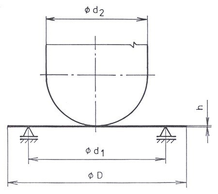
Fig. 1. A plate with the punch
Calculation model
A calculation model needs to be chosen in all FEM calculations. The choice of the calculation model depends on many factors, such as:
- required accuracy of the solution,
- available software,
- level of knowledge (regarding possibilities of solving the given problem),
- the time within which it is necessary to carry out the solution, etc.
If it is necessary, a new calculation with a more accurate calculation model can be carried out. In the given situation, the wood was modelled as a linear elastic material. The so-called second problem of elasticity with given kinematic boundary conditions without respect to the influence of contact of the plate with a punch is solved.
Solving the problem was carried out by the FEM, by means of the software ANSYS. The 8-node orthotropic shell element SHELL 93 was used. The axes of both the local and global coordinate systems x, y, z were identical with the axes of elastic symmetry of the orthotropic material. By acting the rigid punch with its spherical shape on a plate, the displacements, i.e. geometric boundary conditions, are determined by means of a point of the plate on the contact spot with the punch.
The FEM procedure is not difficult, but it is demanding. With such a large number of nodes and elements it is not thinkable to manually input all the data needed for calculation such as the coordinates of individual nodes or assigning individual nodes to relevant elements in the set order. The computer carries out these activities within the preparation of input data by means of the used software. However, when solving a given problem, the finite element software ANSYS is not able to assign new coordinates to the given nodes of a plate, within the contact area of the plate with the punch. It contains, however, APDL (“ANSYS Parametric Design Language“), the scenario language that was designed already in the era of inputting data in punch-cards to make for easier input. Nevertheless, it is applicable nowadays as it supports forming models with variable parameters; this then supports changing the model form very simply.
For calculation and setting kinematic boundary conditions, the language APDL creating a macro, i.e. the corresponding sequence of ANSYS commands saved in a certain file for repeated use, was used. The input variables of the macro are the displacement p of the punch and the number of the plate node for which components of displacement caused by the punch are calculated. On the basis of geometric dependences resulting from the punch displacement, first it is determined whether the given point is in the contact area with the punch. If it is not from the interval of the contact area, the node displacement is not calculated. The coordinates of the examined node are taken over by the macro from the input file ANSYS on the basis of its number. If the given node is from the contact area, the coordinates of the displaced point A1 [r1, z1] in the median plane are calculated in the median plane r – z (Fig. 2) on the basis of the equality of the coordinate r0, in the middle plane of the plate, with a length of twisting a point guide round the punch. By transforming the coordinates of the point from median plane to the global coordinate system, the coordinates of the respective point A1 [x1, y1, z1] are calculated. The components of the displacement of all nodes that are found in the contact area with the punch are calculated from the differences of coordinates of the displaced and the original nodes. The calculated components of node displacement are entered in a file and serve as kinematic boundary conditions of the solved problem.
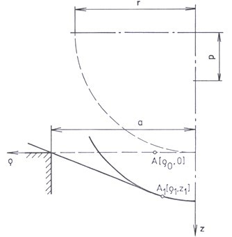
Fig. 2. Position of the point before and after deformation in the median plane
RESULTS AND DISCUSSION
Results
For the reason of a symmetric task, only half of the circular plate was solved. The plane of symmetry is the plane x – z. Numerical results of the solved problem are presented in Figs. 3 through 6. Input numerical values in the calculation were:
- D = 60 mm, h = 0.55 mm, d1 = 50 mm, d2 = 40 mm, p = 3 mm
- Ex = 16, 670 MPa, Ey = 1, 130 MPa, Ez = 630 MPa
- Gxy = 1, 200 MPa, Gxz = 930 MPa, Gyz = 190 MPa
- myx = 0.37, mzx = 0.50, mxy = 0.044, mzy = 0.67, mxz = 0.027, myz = 0.33
Figure 3 illustrates the deflection w of the plate´s middle plane x – y, and Fig. 4 shows the plate deflection in the plane y – z. Figure 5a presents the normal stress sx in the lower plate´s plane and Fig. 5b in the upper one. Figure 6 illustrates the normal stress sy in the plate cutting portion in the plane y – z.
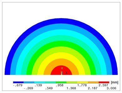
Fig. 3. Deflection w of the middle plane of a plate
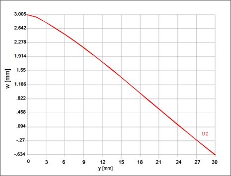
Fig. 4. Deflection w of a plate in the cutting plane y – z
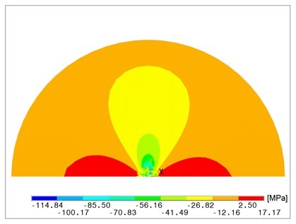
Fig. 5a. Normal stress sx in the lower surface area of the plate
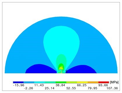
Fig. 5b. Normal stress sx in the upper surface area of the plate
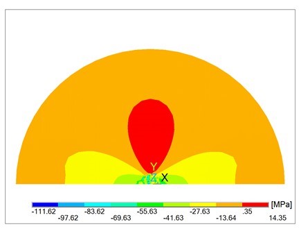
Fig. 6. Normal stress sy in the lower surface of the plate
Discussion
The used numerical solution of the circular orthotropic plate provides the results corresponding to given geometric boundary conditions determined by means of engaging the punch with the oval point onto the plate at a given setting. For the given displacement p of the punch by means of using the “language“ ANSYS Parametric Design Language, the corresponding kinematic boundary conditions prepared to be solved by the software ANSYS were calculated. Manual inputting these kinematic boundary conditions is not feasible as it is considerably demanding.
With simplified boundary conditions, when engaging the punch is simulated only by the displacement of the middle point of the circular plane of the plate, the results are distorted. Comparing Fig. 3 and 4 with Fig. 8 and 10, there is a visible difference in the deflection w of the plate. Figures 5a and 9 point out the differences of the calculated stress sx. Different distribution of normal stress sy is evident of comparison between Fig. 6 and Fig. 11.
With regard to a one-sided relation between the plate and the punch, reactions between the plate and the punch cannot be tensile ones. Therefore, when checking the results, reactions in nodes of the plate and punch contact area were examined first. The nodes with calculated tensile reactions were loosened (without a possibility of the displacement) and repeated calculations were carried out with such corrected boundary conditions. The given graphs are a result of the corrected calculation.
There is also a one-sided connection between the plate and a support. The repeated calculations with loosened connections exhibited tensile reactions with movement of the plate away from the support appearing in these places. Figure 7 shows deflections w in the plate in the places of its support. It is seen that near the x coordinate axis, the bent plate is uplifted over the circular support. Higher values of the punch displacement is shown when wrinkling the plate, which is also confirmed by past studies (Wagenführ and Buchelt 2005; Wagenführ et al. 2006). Higher values of displacement p, however, should be solved as a non-linear problem with large displacements and rotations.
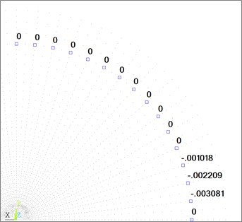
Fig. 7. Deflection w [mm] of the plate in the part of shoring
The mentioned results show that simplification in giving boundary conditions can lead to distorted results of the simulated task that a plate with given numerical values cannot be solved with sufficient accuracy with the used simplified boundary conditions.
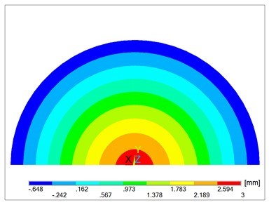
Fig. 8. Deflection w of a plate with simplified boundary conditions
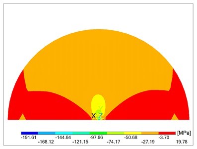
Fig. 9. Normal stress sx in the lower plane with simplified boundary conditions
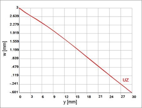
Fig. 10. Deflection w of a plate in the cutting plane y – z with simplified boundary conditions
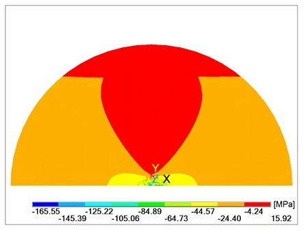
Fig. 11. Normal stress sy in the lower surface area of the plate with simplified boundary conditions
CONCLUSIONS
- The reported results show that simplification in giving boundary conditions can lead to distorted results. Thus, the simulated model for a plate with given numerical values cannot be solved accurately with the used simplified boundary conditions.
- When solving problems of mechanics in ANSYS without using APDL, the setting of more complicated geometric boundary conditions is difficult to accomplish. Therefore the solution in ANSYS requires APDL application.
- With the formed macro it is possible to repeatedly solve plate tensity and deformation caused by a spherical shape of the punch for different numerical values of material as well as geometric input data.
ACKNOWLEDGMENTS
The article has been written on the basis of research intention and solution of the research grant project: VEGA no. 1/0422/12 “Modifying of wood properties for the purposes of its 3-D forming.”
REFERENCES CITED
Fekiač, J., Zemiar, J., Gaff, M., Gáborík, J., and Gašparík, M. (2015). “3D-Moldability of veneers plasticized with water and ammonia,” BioResources 10(1), 866-876. DOI: 10.15376/biores.10.1.866-876
Lang, M., and Langová, N. (1998). “Štúdium vplyvu anizotropie materiálu na koncentráciu napätia okolo otvorov,” Acta Mechanica Slovaca 2(2), 91-94. ISSN (Print) 1335-2393
Langová, N., and Joščák, P. (2014). “Effect of mechanical modification of wood veneers on their planar formability,” Annals of Warsaw University of Life Sciences 87, 142-147.
Lechnickij, S. G. (1957). “Anizotropnyje plastinki,” [Anisotropic plates], 2nd Edition revised and completed. Moskva: Gostechizdat.
Sobotka, Z. (1989). “Theory of plasticity and limit design of plates,” Studies in Applied Mechanics, Elsevier Science Ltd. DOI: 10.1016/B978-0-444-98907-9.50004-4
Ukadgaonker, V. G., and Rao, D. K. N. (2000). “A general solution for moments around holes in symmetric laminates,” Composite Structures 49(1), 41-54. DOI: 10.1016/S0263-8223(99)00124-5
Wagenführ, A., and Buchelt, B. (2005). “Untersuchungen zum Materialverhalten beim dreidimensionalen Formen von Furnier,” Holztechnologie 46(1), 13-19.
Wagenführ, A., Buchelt, B., and Pfriem, A. (2006). “Material behavior of veneer during multidimensional moulding,” Holz als Roh- und Werkstoff 64(2), 83-89. DOI: 10.1007/s00107-005-0008-5
Zemiar, J., and Fekiač, J. (2014). “Skúšanie a hodnotenie 3D – tvárnosti dýh. 2014. Skúšanie a hodnotenie 3D – tvárnosti dýh,” Acta Facultatis Xylologiae Zvolen: The Scientific Journal of the Faculty of Wood Sciences and Technology 56(1), 31-38. ISSN 1336-3824
Zemiar, J., Fekiač, J., and Gáborík, J. (2014). “Strengthening of veneers for 3D-forming,” Annals of Warsaw University of Life Sciences 88(2014), 297-303.
Article submitted: June 10, 2015; Peer review completed: Sept. 19, 2015; Revised version received and accepted: November 12, 2015; Published: December 4, 2015.
DOI: 10.15376/biores.11.1.1061-1070