
Abstract
Humidity and temperature conditions have a substantial influence on the stresses and total deformation of timber-concrete composite panels, especially in terms of the high rigidity of the shear connection. In the present research, the normal stresses that resulted from the hygrothermal load of timber-concrete composite panels with an adhesive shear connection were analyzed. Three timber-concrete composite panel specimens were placed in controlled climate conditions. Strains in two orthogonal directions were measured. The stress distribution resulted from an approximate analytical calculation model. The results show that the highest stresses occurred near the shear connection. An increase in timber moisture content by 2.1% was predicted to result in exceeding the flexural tensile strength in the concrete perpendicular to the timber grain direction. At an outdoor temperature range, stresses influenced only by the temperature alone will possibly not cause a failure of timber or concrete. Under winter environmental conditions, the stress in timber can possibly reach 12% of the bending strength of the timber used.
Download PDF
Full Article
Normal Stress Distribution of Timber-Concrete Composite Panels with an Adhesive Shear Connection under Thermal and Humidity Loadings
Viktória Bajzecerová,a,* Ján Kanócz,b Eva Kormaníková,a Viktor Karľa,a Peter Orolin,a and František Vranay a
Humidity and temperature conditions have a substantial influence on the stresses and total deformation of timber-concrete composite panels, especially in terms of the high rigidity of the shear connection. In the present research, the normal stresses that resulted from the hygrothermal load of timber-concrete composite panels with an adhesive shear connection were analyzed. Three timber-concrete composite panel specimens were placed in controlled climate conditions. Strains in two orthogonal directions were measured. The stress distribution resulted from an approximate analytical calculation model. The results show that the highest stresses occurred near the shear connection. An increase in timber moisture content by 2.1% was predicted to result in exceeding the flexural tensile strength in the concrete perpendicular to the timber grain direction. At an outdoor temperature range, stresses influenced only by the temperature alone will possibly not cause a failure of timber or concrete. Under winter environmental conditions, the stress in timber can possibly reach 12% of the bending strength of the timber used.
Keywords: Timber-concrete composite; Adhesive shear connection; TCC slab; Temperature; Moisture; Hygrothermal behavior; Hygrothermal stress
Contact information: a: Faculty of Civil Engineering, Technical University of Košice, Vysokoškolská 4, Košice 042 00 Slovakia; b: Faculty of Arts, Technical University of Košice, Letná 9, Košice 042 00 Slovakia; *Corresponding author: viktoria.bajzecerova@tuke.sk
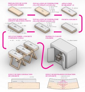
GRAPHICAL ABSTRACT
INTRODUCTION
Timber-concrete composite (TCC) systems with mechanical fasteners are commonly used and are relatively extensively studied (Dias et al. 2018). However, mechanical fasteners are unable to ensure a rigid connection and result in a relative slip between the timber and concrete. An almost perfectly rigid connection can be provided using adhesives to bond a concrete layer to timber (Brunner et al. 2007; Negrão et al. 2010; Kanócz and Bajzecerová 2015; Schmid et al. 2016; Fu et al. 2020). Although multiple studies on TCC with an adhesive connection have been performed, the bonding of wood and concrete using adhesive is not yet common in practice. Thus, it requires further investigation in multiple fields of research, e.g., low ductility of the connection, long term behavior, impact of humidity and thermal changes, or its performance during a fire.
The elimination of brittle failure was the aim of the research by Tannert et al. (2020), where hybrid TCC floors combined with self-tapping screws with an adhesive layer were presented. Their long-term behavior was investigated by Eisenhut et al. (2016), Tannert et al. (2017), and Bajzecerová and Kanócz (2019), and the results showed that the adhesive was not the weak link in the long-term performance and durability of TCC. The composite action was unaffected by long-term loading. However, the results showed that due to the high rigidity of the connection, there is a substantial influence from the humidity and temperature conditions on the stress and deflection of the TCC over time.
Timber, concrete, and adhesive have different hygrothermal properties; in addition, timber has different mechanical and hygrothermal properties in various directions, being an orthotropic material (Rindler et al. 2017; Chiniforush et al. 2019). The changing temperature and moisture cause internal stresses when components are bonded together (Bagoňa et al. 2011; Ginz and Seim 2018; Fortino et al. 2019; Fojtík et al. 2020). The uneven thermal and humidity deformations of each layer of the TCC can lead to the local failure of the timber or concrete part or the delamination of the composite panel (Song et al. 2021). The calculation of the hygrothermal stresses and strains of a layered beam can be based on classical layer beam theory (Zabulionis 2006). The effect of hygrothermal load on TCC is explained in Fig. 1.

Fig. 1. Influence of temperature decrease on TCC cross-section as an example of the hygrothermal load effect
In previous long-term bending tests, TCC beams were placed in practically uncontrolled hygrothermal conditions and the creep of the material and drying shrinkage of the concrete were the main phenomena that influenced the measured values of strains and deflection (Eisenhut et al. 2016; Bajzecerová and Kanócz 2019; Tannert et al. 2020). The influence of the changes in temperature and humidity on the behavior of TCC with the adhesive shear connection was not yet studied independently, nor under controlled hygrothermal conditions.
The aim of the research, presented herein, was to analyze the normal stresses of TCC panels with an adhesive shear connection that resulted only from the hygrothermal load without other effects, e.g., creep due to gravity load and shrinkage of concrete. Three TCC panel specimens with the adhesive shear connection were subjected to temperature and humidity loadings in a climate chamber. Within the test, the temperature, moisture content, and strain in two orthogonal directions were measured. To evaluate the measured data, an approximate analytical calculation model was used.
EXPERIMENTAL
Materials
Three TCC specimens, all of them 300 mm wide and 750 mm long, were prepared (Fig. 2). The timber part was made up of an 80 mm thick glued laminated timber panel (Picea abies). Sikadur®-32 (a bonding agent) was spread on the upper surface of the timber panels, and within the following 30 min, 50 mm thick concrete layers were cast. Two other specimens with dimensions of 300 mm × 450 mm were prepared, one timber slab and one concrete slab of the same material as the TCC specimens. All specimens were kept stored in a laboratory for two years before testing. The drying shrinkage of the concrete was only expected to have a negligible effect on the test results (Kušnirová and Priganc 2019).
The modulus of elasticity, cylinder compressive strength, and flexural tensile strength of the concrete were defined according to EN standard 12390 (2013), with mean values of 26 GPa, 55 MPa, and 8.1 MPa, respectively, at the concrete age of 371 days. Poisson’s ratio of concrete was assumed at a value of 0.18 according to EN standard 1992-1-1 (2015). The density of concrete was 2295 kg/m3.
The modulus of elasticity and bending strength of the timber parallel to the grain were determined according to EN standard 408 (2013), with mean values of 13.9 GPa and 50 MPa, respectively. The modulus of elasticity of the timber perpendicular to the grain was 0.463 GPa, as determined according to EN standard 338 (2010). The value of the Poisson’s ratio of timber was assumed at a value of 0.5. The density of the timber was 425 kg/m3.
According to the manufacturer data of Sikadur®-32 (Sika 2017), the modulus of elasticity, coefficient of thermal expansion, and Poisson’s ratio of the adhesive are 4.0 GPa, 8.210-5 1/°C, and 0.3, respectively.
Within the concrete part of specimens, no structural reinforcement was used. According to Dias et al. (2018), the purpose of the reinforcement in TCC is to control cracking in order to maintain the integrity of the mechanical shear connection. The adhesive ensures the integrity of the connection in the whole contact surface. In addition, the concrete layer is intended to act in compression due to external load. Therefore, no reinforcement has been designed.

Fig. 2. Preparation and dimensions (mm) of the TCC panels (TC1, TC2, and TC3), timber (T), and concrete (C) specimens; (1) – fresh bonding agent Sikadur®-32, (2) – strain gauge
Methods
The specimens were placed in an air-conditioned chamber and exposed to an environment with varying relative humidity (ranging from 45% to 85%) and temperature (ranging from 10 °C to 35 °C). The Thermotron WP-2(527)-2(THCM1-5) (Thermotron Industries, Holland, MI) chamber enables full-scale testing of specimens up to 2.5 m x 2.0 m at the interface of two different environments under a wide range of precisely controlled boundary conditions, including temperature and relative humidity (Fig. 3a). The data detailing the ambient temperature, ambient relative humidity, and temperature gauges at various depths of the specimens (Fig. 3b) were stored using the data acquisition system ALMEMO 5690-2 (Ahlborn, Holzkirchen, Germany) at 15 min intervals.

Fig. 3. (a) Air-conditioned chamber and measurement device; (b) position of the temperature gauges (TG) placed in the pre-drilled holes with a specific depth (in parentheses) from the timber (-T) and concrete (-C) surface; and (c) the temperature gauges
Strains were measured via the strain gauges with a length of 100 mm placed on top of the concrete and the bottom of the timber part in both the x-direction and the y-direction (Fig. 4). Another strain gauge with a length of 50 mm was fixed on the top timber surface before concreting in the x-direction (Fig. 2). The data from the strain gauges (SG) were acquired using the Quantum MX 840 (HBM, Darmstadt, Germany) universal measurement amplifier module at 50 s intervals.

Fig. 4. (a) Test set-up; and (b) position of strain gauges (SG) on the bottom timber (-T), top timber (-M), and top concrete (-C) surface of TCC specimens

Fig. 5. (a) Measurement of the timber moisture content; and (b) position of the measuring points
The moisture content was measured at 6 measuring points on the timber (HG in Fig. 5b) after stabilizing the strain values in time at the end of each test phase with constant environmental conditions. A two pins moisture content resistance meter WHT 770 (ELBEZ, Velké Meziříčí, Czech Republic) was used (Fig. 5a).
Calculation Model
For the evaluation of the measured strains, as well as the preliminary theoretical analysis, an approximate analytical model was used. The calculation model considered the linear behavior of the bonded materials as well as the linear strain and stress distribution (Bajzecerová et al. 2020). It was assumed that all relevant mechanical properties were uniform throughout each layer and independent of any temperature and moisture content.
The measured strain during the test corresponded to the total strain i (m/m), which is the sum of the thermal strain, humidity strain, and elastic strain due to the constrained deformation of all bonded layers, as calculated according to Eq. 1,
 (1)
(1)
where is the thermal strain (m/m), is the humidity strain (m/m), and is the elastic strain (m/m) of the ith-layer of the TCC panel. These variables were calculated according to Eq. 2, Eq. 3, and Eq. 4,
 (2)
(2)
 (3)
(3)
 (4)
(4)
where αi,u and αi,Θ are coefficients of the moisture expansion (m/m) and thermal expansion (1/°C), respectively (which were obtained from the test measurements of timber and concrete specimens), ∆ui is the change in moisture content (-), ∆Θi is the change in temperature (°C) of the ith-layer, (m/m) and (m/m) are the elastic strain components of the ith-layer. These variables were calculated by Eq. 5 and Eq. 6, respectively,
 (5)
(5)
 (6)
(6)
where Ei is the modulus of elasticity (MPa), Ii is the moment of inertia (m4), Ai is the cross-section area (m2), ai is the distance of gravity from the center of gravity of the composite cross-section (m), and hi is the depth of the ith-layer (m).
The orthotropic material property for timber can be reduced to a transversely isotropic material in two orthogonal directions, i.e., the x– and y-axis. In this context, the stress-strain relationship of the ith-layer of TCC panels can be expressed by Eq. 7,
 (7)
(7)
where ix and iy are the stresses (MPa) of the ith-layer in the x-direction and y-direction, respectively, and ixy and iyx are the Poisson’s ratios (-) calculated using Eq. 8,
 (8)
(8)
The moisture content varies in time and over the cross-section according to the diffusion laws (Toratti 1992; Fortino et al. 2019) and the process depends on the diffusion coefficient, surface emissivity of timber, and moisture content flux through the boundary of the timber cross-section. The temperature and humidity distribution in the TCC cross-section is not uniform after a change in temperature and relative humidity of the environment. For relatively small TCC cross-sectional depths, a simplification of the uniform temperature and humidity of each layer may be used (Dias et al. 2018). For simplicity, the calculation model does not consider the uneven temperature and humidity profiles in the cross-section.
RESULTS AND DISCUSSION
Thermal and Humidity Load
The climate chamber was initially set at a temperature of 20 °C and a relative humidity (RH) of 65% for 12 d. According to the temperature and humidity gauges placed in the chamber, the initial conditions of the environment were 20.3 °C and a RH of 69.4%. The timber moisture content was stabilized at 14%.
The measured relative humidity of the environment was higher than the set values during the whole test (Fig. 6a). The relative humidity of the climate chamber was set at 65%, 85%, and 45%. The respective average relative humidity levels measured via the gauges in the chamber were 69.4% to 72.0%, 86.8% to 88.5%, and 52.0%.

Fig. 6. (a) Temperature (Θ) and relative humidity of the environment; (b) adapting of specimens to ambient temperature – average data from temperature gauges (TG) at various depths from the surface of timber (-T) and concrete (-C)
In the case of the temperature, the measured values in the climate chamber were equal to the set values with a relatively small difference. The temperature of the climate chamber was set at 10 °C, 20 °C, and 35 °C; the respective measured values in the chamber were 10.9 °C, 20.3 °C, and 34.5 °C.
The concrete and timber portions of the specimens adapted differently to temperature changes. Figure 6b shows the time-temperature relationship measured via the temperature gauges in different depths of timber and concrete after the increase in ambient temperature by 14.3 °C. Concrete has a higher thermal conductivity than timber. The concrete portion of the specimens adapted to the higher temperature approximately after 18 h. The temperature gauge at a depth of 70 mm from the timber surface was influenced by the close contact with concrete. The temperature measured at a depth of 40 mm was lower than the measurements at 70 mm in the whole temperature level duration with a difference of 0.3 °C. A similar effect was observed at other temperature levels. Nevertheless, the uniform temperature in the whole depth of the specimens was considered in the calculation.
Five different environments were set (Fig. 7). The moisture content of the timber was measured at the end of the respective test phases, in which the settings of the environment were constant. When the relative humidity of the chamber was set at 65%, the timber moisture content reached 14%, regardless of the temperature. At a relative humidity level of 85% and 45%, the timber moisture contents were 15.9% and 11.5%, respectively. Each relative humidity level in the environment lasted for at least 12 d.

Fig. 7. Measured timber moisture content depending on the setting of the climate chamber; Θ – temperature and RH – relative humidity; the box and whiskers plots show the median (horizontal line in the box), the 50% interquartile range (box), the 5% and 95% quartile (whiskers) and extreme values (+).
Thermal and Humidity Expansion Coefficients
The coefficients of the thermal and humidity expansion of concrete and timber resulted from the strain measurements of the specimens (as shown in Fig. 4a) of concrete C (εC) and timber T in both the x and y direction (εTx and εTy, respectively). The values of the coefficients are listed in Table 1 and were calculated as a ratio of the differences of measured strains (∆ε) and differences of temperature (∆Θ (°C)) or moisture content of the timber (∆u (-)) between two test phases, according to Eqs. 9 to 13,
 (9)
(9)
 (10)
(10)
 (11)
(11)
 (12)
(12)
 (13)
(13)
where αi,Θ and αi,u are the coefficients of thermal expansion (1/°C) and moisture expansion (m/m), respectively, and subscript i = 1 denotes the concrete and i = 2 the timber layer.
In the case of the concrete specimen, the strain changes dependent on changes in the relative humidity of the environment were observed. Therefore, the coefficient of moisture expansion of concrete relative to the change in relative humidity of the environment ∆RH (-) was set according to Eq. 14,
 (14)
(14)
The humidity strain of the concrete layer (m/m) defined in the calculation model by Eq. 3 was replaced by Eq. 15,
 (15)
(15)

To calculate the thermal expansion coefficients, only the strain differences between the two test phases in which the relative humidity of the environment was the same, e.g., the strain difference between phase 20 °C / 65% and phase 35 °C / 65%, etc., were used. Similarly, to calculate the moisture expansion coefficients, only the strain differences between the two test phases in which the temperature was the same, e.g., the strain difference between phase 20 °C / 65% and phase 20 °C / 85%, etc., were used.
Comparison of the Measured and Calculated Strains
In Fig. 8, the strains over the cross-section of the TCC panels parallel to the timber grain (x) and perpendicular to the timber grain (y) are presented. The plotted values correspond to the strain differences between each of the four test phases and the initial phase, which was characterized by a temperature of 20.3 °C, a relative humidity of 69.4%, and a timber moisture content of 14%. The test values of specimens TC1, TC2, and TC3 are given in comparison with the calculated values. The strain gauge SG-Mx on the top timber surface of the TC1 panel malfunctioned.

Fig. 8. Measured and calculated strains over the cross-section of TCC panels in parallel (x) and perpendicular to the grain (y) caused by hygrothermal changes relative to the initial conditions; Θ – temperature, u – timber moisture content, RH – relative humidity, SG – strain gauge
Although the calculation model was simplified and did not consider the uneven temperature and humidity profiles in the cross-section, it predicted the measured strains relatively well. The ratios of the measured and calculated values had a coefficient of variation (CoV) of 1.45, which was primarily caused by the poor match of the measured and calculated values on the bottom surface of the timber parallel to the grain (x). The CoV of these ratios in the y-direction ranged from 0.24 to 0.59. Based on the comparison, the model was considered suitable for the estimation of the stresses in the TCC specimens due to the thermal and humidity load.
Normal Stress Distribution in the TCC Cross-Section
Using the calculation model, the stress values in four different environmental conditions over the TCC cross-sections were evaluated. The stress arose from the restrained thermal and humidity deformation of both the timber and concrete parts of the panels due to the rigid shear connection. The stress values in both the x and y directions are plotted in Fig. 9 and correspond to the increments of the stresses relative to the initial conditions. The largest increase in stress was near the shear connection.

Fig. 9. Calculated stresses over the cross-section of TCC panels in parallel (x) and perpendicular to the grain (y) caused by hygrothermal changes relative to the initial conditions; Θ – temperature, u – timber moisture content, RH – relative humidity, SG – strain gauge
Influence of the temperature changes
In the x-direction, the temperature change caused greater deformations in the concrete layer since concrete has a higher coefficient of thermal expansion than timber parallel to the grain (x). A decrease in temperature by 9.3 °C (as shown in Fig. 9: Θ = 11 °C and u = 14%) was predicted to cause tensile stresses on the bottom surface of the concrete (+1.29 MPa) and compressive stresses on the top surface of the timber (-1.12 MPa). However, an increase in temperature by 14.3 °C (as shown in Fig. 9: Θ = 34.6 °C and u = 14%) was predicted to cause an increase in compressive stress on the bottom surface of the concrete (-2.06 MPa) and tensile stress on the top surfaces of the timber (+1.78 MPa). Theoretically, when the temperature decreases by 58.5 °C (to a temperature of -38.2 °C), the normal stress (x) could reach the flexural tensile strength of concrete used (+8.1 MPa).
Perpendicular to the timber grain (y), the effect of the temperature change was opposite to the x-direction. The reason was that the thermal expansion coefficient of timber perpendicular to grain was higher compared to the thermal expansion coefficient of concrete. Theoretically, with a temperature increase of 67 °C (to a temperature of 87.3 °C), the normal stress (y) could reach the flexural tensile strength of the concrete used (+8.1 MPa).
It can be stated that under real conditions using TCC specimens, the influence of temperature alone should not lead to the failure of the concrete or timber.
Influence of the humidity changes
The change in relative humidity of the environment had a more substantial effect on the normal stresses than the temperature changes. As can be observed from the measurements, the concrete also reacted to changes in the relative humidity of the environment, but at a lower ratio compared to the timber. In the case of an increase in the relative humidity of the environment by 19.1%, the timber moisture content increased by 2.1% (as shown in Fig. 9: Θ = 20.3 °C and u = 16.1%), which caused an increase in the timber strain, especially perpendicular to the grain (x). The increase in the timber strain caused tensile stresses on the bottom surface of the concrete layer perpendicular to the grain (y) with a predicted value of +8.35 MPa, which is greater than the flexural tensile strength of concrete. The decrease in timber moisture content causes the opposite effect; the tensile stresses arise on the top surface of the concrete.
Influence of the seasonal temperature and humidity changes
In the last phase of the testing, summer environmental conditions were set (as shown in Fig. 9: Θ = 34.3 °C and u = 11.4%). The relative humidity of the environment decreased by 17.6%, the timber moisture content decreased by 2.6%, and the temperature of the environment was 14 °C higher than the initial conditions. For the normal stresses in the x-direction, the increase in temperature and the decrease in timber moisture caused similar stress profiles, so the influence of both effects increased the normal stresses (x). However, in the y-direction, the increase in temperature had the opposite stress profile and reduced the values of stress (y) influenced by a decrease of humidity. In this phase, the highest tensile stress was predicted on the top surface of the concrete and reached a theoretical value of +6.43 MPa, which is 78% of the flexural tensile strength of the concrete used. A compressive stress of -8.7 MPa was calculated on the bottom surface of the concrete, which is 16% of the cylinder compressive strength of the concrete used.
The applied thermal and humidity load did not cause a failure of the specimen, which was also confirmed by the calculated normal stress values. The limit value was theoretically reached on the bottom surface of the concrete layer, but the strains on this surface were not measured, nor were any vertical cracks observed.
Theoretically, winter environmental conditions, i.e., an increase in the timber moisture content by 3% (at a relative humidity of approximately 90%) in combination with a decrease in the temperature by 35.3 °C (to a temperature of -15 °C), could lead to exceeding the flexural tensile strength of concrete in the bottom concrete surface and the stress in the top timber surface with a predicted value of -5.8 MPa, which is 12% of the bending strength of the timber used.
The relatively high values of inelastic hygrothermal stresses together with stresses due to external static load can cause the failure of TCC panels. According to the calculation, the timber resistance would be reduced by up to 5.8 MPa due to inelastic stress in winter temperature and humidity conditions, while the design value of the timber can reach about 17 MPa. This indicates an important effect of hygrothermal load and confirms that the inelastic strains need to be considered when designing the TCC with the adhesive connection, especially when used outdoors. In addition, the hygrothermal strains cause a curvature of the panels and might cause a relatively high value of deflection, which affects the serviceability of the TCC panels. However, hygrothermal deformations are reversible in accordance with the yearly variations of the environment (Bajzecerová and Kanócz 2019), in contrast to failures caused by the high stresses due to external and hygrothermal load.
Constraints and perspectives
The temperature and the moisture content in the layers of relatively small depth, such as in the case of the analyzed specimens with a concrete depth of 50 mm and a timber depth of 80 mm, can be assumed as constant throughout the whole depth. In a larger TCC member, the variation of the temperature and moisture content in the composite cross-section should be considered. Other effects, such as the hysteresis on the timber moisture content, the cracking in the tension of timber and concrete, or the moisture-induced stresses perpendicular to the grain could contribute to a better understanding of the issue.
The applied thermal and humidity load in the presented experimental analysis did not cause an apparent shear failure. No evidence of shear failure was detected in the behavior of specimens measured by the strains. Shear stresses in the adhesive connection caused by the thermal and humidity loading will be analyzed in future works. Further research is still needed to fully address the complex topic of the adhesive connection of TCC.
CONCLUSIONS
- The highest stress values in the TCC panels due to thermal and humidity load arise near the glue line, i.e., on the top surface of the timber or the bottom surface of the concrete. The weakest point is the tensile stress in the concrete layer, which has a relatively low tensile strength.
- Under common outdoor conditions, using TCC panels at a temperature range of -20 °C to 40 °C, the stresses caused by temperature alone will possibly not cause a failure in the timber or the concrete.
- According to the calculation model, due to a 2.1% increase in timber moisture content, the flexural tensile strength of concrete on the bottom surface was exceeded perpendicular to the timber grain. Neither the compressive strength of the concrete or the compressive strength of the timber was reached.
- In the test phase under summer environmental conditions, i.e., a decrease in timber moisture content by 2.6% and an increase of ambient temperature by 14 °C, the compressive stress on the bottom surface of the concrete was calculated with a value of 16% of the cylinder compressive strength and the tensile stress on the top surface of the concrete had a value of 78% of the flexural tensile strength of the concrete used.
- In the case of the winter environmental conditions, i.e., the timber moisture content could increase by 3% and the temperature could decrease to -15 °C, the stress on the bottom surface of the concrete would probably exceed the flexural tensile strength of concrete and the stress on the top surface of the timber would reach a value of -5.8 MPa, accounting for 12% of the bending strength of the timber used.
ACKNOWLEDGMENTS
This scientific paper resulted from the implementation of the project: University Science Park TECHNICOM for Innovation Applications Supported by Knowledge Technology (ITMS: 26220220182) and was supported by the Research & Development Operational Programme, which was funded by the ERDF.
This work was supported by the Scientific Grant Agency of the Ministry of Education of the Slovak Republic and the Slovak Academy of Sciences under VEGA Projects 1/0374/19 and KEGA 046TUKE-4/2019.
REFERENCES CITED
Bagoňa, M., Lopušniak, M., and Vertaľ, M. (2011). “Numerical analysis of the hygrothermal performance of selected building structures in Slovak climatic conditions,” in: Proceedings of the Building Simulation 2011: 12th Conf. of Internat. Building Performance Simulation Association, Sydney, Australia, pp. 2263-2268.
Bajzecerová, V., and Kanócz, J. (2019). “Long-term bending test of adhesively bonded timber-concrete composite slabs,” in: Advances and Trends in Engineering Sciences and Technologies III, M. A. Ali, and P. Platko (ed.), CRC Press, London.
Bajzecerová, V., Kormaníková, E., and Kanócz, J. (2020). “Hygrothermal performance of timber-concrete composite panels – Theoretical investigation,” in: Proceedings of the 4th International Scientific Conference Structural and Physical Aspects of Construction Engineering (SPACE 2019), Štrbské Pleso, Slovakia, pp. 38-44.
Brunner, M., Romer, M., and Schnüriger, M. (2007). “Timber-concrete composite with an adhesive connector (wet-on-wet process),” Materials and Structures 40(1), 119-26. DOI: 10.1617/s11527-006-9154-4
Chiniforush, A. A., Akbarnezhad, A., Valipour, H., and Malekmohammadi, S. (2019). “Moisture and temperature induced swelling/shrinkage of softwood and hardwood glulam and LVL: An experimental study,” Construction and Building Materials 207, 70-83. DOI: 10.1016/j.conbuildmat.2019.02.114
Dias, A., Schänzlin, J., and Dietsch, P. (2018). Design of Timber-Concrete Composite Structures (FP1402/WG 4), European Cooperation in Science and Technology, Brussels, Belgium.
Eisenhut, L., Seim, W., and Kühlborn, S. (2016). “Adhesive-bonded timber-concrete composites – Experimental and numerical investigation of hygrothermal effects,” Engineering Structures 125, 167-178. DOI: 10.1016/j.engstruct.2016.05.056
EN 12390 (2013). “Testing hardened concrete,” European Committee for Standardization, Brussels, Belgium.
EN 1992-1-1 (2015). “Eurocode 2: Design of concrete structures – Part 1-1: General rules and rules for buildings,” European Committee for Standardization, Brussels, Belgium.
EN 338 (2010). “Structural timber – Strength classes,” European Committee for Standardization, Brussels, Belgium.
EN 408 (2013). “Timber structures. Structural timber and glued laminated timber. Determination of some physical and mechanical properties,” European Committee for Standardization, Brussels, Belgium.
Fojtík, R., Kubíncová, L., Dubovský, V., and Kozlová, K. (2020). “Moisture at contacts of timber-concrete element,” Wood Research 65(6), 917-924. DOI: 10.37763/wr.1336-4561/65.6.917924
Fortino, S., Hradil, P., and Metelli, G. (2019). “Moisture-induced stress in large glulam beams. Case study: Vihantasalmi Bridge,” Wood Material Science and Engineering 14(3), 366-380. DOI: 10.1080/17480272.2019.1638828
Fu, Q., Yan, L., Ning, T., Wang, B., and Kasal, B. (2020). “Behavior of adhesively bonded engineered wood – Wood chip concrete composite decks: Experimental and analytical studies,” Construction and Building Materials 247, Article ID 118578. DOI: 10.1016/j.conbuildmat.2020.118578
Ginz, A., and Seim, W. (2018). “Moisture-induced internal stress within adhesive-bonded timber-concrete composites,” in: Proceedings of the World Conference on Timber Engineering, Seoul, South Korea, pp. 1-6.
Kanócz, J., and Bajzecerová, V. (2015). “Timber – Concrete composite elements with various composite connections. Part 3: Adhesive connection,” Wood Research 60(6), 939-952.
Kušnirová, D., and Priganc, S. (2019). “Slab deformations caused by shrinkage – Experiment vs. numerical calculation,” in: IOP Conference Series: Materials Science and Engineering 566, 1-5. DOI: 10.1088/1757-899X/566/1/012020
Negrão, J. H. J. d. O., de Oliveira, F. M. M., de Oliveira, C. A. L., and Cachim, P. B. (2010). “Glued composite timber-concrete beams. II: Analysis and tests of beam specimens,” Journal of Structural Engineering 136(10), 1246-54. DOI: 10.1061/(ASCE)ST.1943-541X.0000251
Rindler, A., Vay, O., Hansmann, C., and Müller, U. (2017). “Dimensional stability of multi-layered wood-based panels: A review,” Wood Science and Technology 51, 969-996. DOI: 10.1007/s00226-017-0940-7
Schmid, V., Zauft, D., and Polak, M. (2016). “Bonded timber-concrete composite floors with light-weight concrete,” in: Proceedings of the World Conference on Timber Engineering, Vienna, Austria, pp. 4360-4367.
Sika, A. G (2017). Product Data Sheet Sikadur®-32 Normal, Sika AG, Baar, Switzerland.
Song, Y.-J., Baek, S.-Y., Lee, I.-H., and Hong, S.-I. (2021). “Variations of moisture content in manufacturing CLT-concrete composite slab using wet construction method,” BioResources 16(1), 372-386. DOI: 10.15376/biores.16.1.372-386
Tannert, T., Endacott, B., Brunner, M., and Vallée, T. (2017). “Long-term performance of adhesively bonded timber-concrete composites,” International Journal of Adhesion and Adhesives 72, 51-61. DOI: 10.1016/j.ijadhadh.2016.10.005
Tannert, T., Gerber, A., and Vallee, T. (2020). “Hybrid adhesively bonded timber-concrete-composite floors,” International Journal of Adhesion and Adhesives 97, Article ID 102490. DOI: 10.1016/j.ijadhadh.2019.102490
Toratti, T. (1992). Creep of Timber Beams in Variable Environment, PhD thesis, Helsinki University of Technology, Laboratory of Structural Engineering and Building Physics.
Zabulionis, D. (2006). “Stress and strain analysis of layered beams under hygrothermal and mechanical loads,” Mechanika 59(3), 28-33.
Article submitted: March 1, 2021; Peer review completed: April 25, 2021; Revised version received and accepted: May 10, 2021; Published: May 13, 2021.
DOI: 10.15376/biores.16.3.4862-4875