
Abstract
To analyze the influence of the milling parameters, including the spindle speed, feed rate, axial cutting depth, and radial cutting depth, on the milling force during high-speed milling of wood-plastic composites, an orthogonal test was performed with carbide cutting tools. The results showed that the tangential (Fx) and radial forces (Fy) decreased with an increase in the spindle speed, increased with an increase in the feed rate, and increased with an increase in the axial milling depth. Also, both were influenced by a relatively small amount of change in the axial milling depth. Mathematical models of Fx and Fy during the high-speed milling of wood-plastic composites were established with a multiple linear regression method. The variance analysis showed that the two mathematical models of the milling forces were significant overall.
Download PDF
Full Article
Research on Milling Forces During High-speed Milling of Wood-plastic Composites
Weihua Wei,a,b,* Yuantong Li,b Tongming Xue,b Xiao Liu,a Long Chen,a Jian Wang,a Tongyue Wang,a and Yaning Cai c
To analyze the influence of the milling parameters, including the spindle speed, feed rate, axial cutting depth, and radial cutting depth, on the milling force during high-speed milling of wood-plastic composites, an orthogonal test was performed with carbide cutting tools. The results showed that the tangential (Fx) and radial forces (Fy) decreased with an increase in the spindle speed, increased with an increase in the feed rate, and increased with an increase in the axial milling depth. Also, both were influenced by a relatively small amount of change in the axial milling depth. Mathematical models of Fx and Fy during the high-speed milling of wood-plastic composites were established with a multiple linear regression method. The variance analysis showed that the two mathematical models of the milling forces were significant overall.
Keywords: Wood-plastic composites; High-speed milling; Milling force; Mathematical model
Contact information: a: Jiangsu Province Key Laboratory of Advanced Manufacturing Technology, Huaiyin Institute of Technology, Huai’an, 223003, China; b: College of Mechanical and Electrical Engineering, Nanjing Forestry University, Nanjing, 210037, China; c: Jiangsu Hengyuan International Engineering Co. Ltd., Yangzhou, 225266, China; *Corresponding author: whwei@njfu.edu.cn
INTRODUCTION
Presently, there are many methods to cut wood, wood composite boards, wood-plastic composites (WPCs), and other wood materials. These methods mainly include sawing, milling, drilling, grinding, turning, and others. Among them, milling is the most important shaping process for forming the surface and obtaining complex geometries, and it is widely used in the second forming process. High-speed milling technology is particularly important in industries where mass production models are used, such as in the automobile, furniture, and building material industries. High-speed milling technology has many advantages, such as increasing the production efficiency, reducing the cutting force, improving the machining precision and surface quality, reducing the costs, etc., and it has been widely used in the aviation, aerospace, and automotive sectors, as well as other manufacturing sectors (Byrne et al. 2003; Wei et al. 2012, 2018). In these sectors, aluminum alloy, cast iron, alloy steel, titanium alloy, high temperature alloy, quenched steel, and other metal materials are widely used. Compared with these metal materials, WPCs are anisotropic and heterogeneous, which leads to a large amount of milling vibration and noise during high-speed milling, increased difficulty of chip removal, and the production of a large amount of chip dust at a high removal rate. It also leads to difficulty in guaranteeing the machining accuracy and surface quality, and deterioration of the processing environment (Kılıç et al. 2009). In the study of cutting forces, Đurković, et al. (2018) analyzed the influence of cutting regime elements and tool geometry on cutting force and established a cutting force prediction model. Darmawan and associates pointed out that the coated carbide tools are more advantageous in reducing the progression of tool wear and retaining lower normal force and noise level (Darmawan et al. 2001a,b; Darmawan and Tanaka 2004). However, these studies were based on wood and wood-based materials, and did not involve substantial research on WPCs.
A typical WPC was used as the test object and an orthogonal experiment design was applied as an experimental design in this study to study the effects of the cutting parameters, including the spindle speed, feed rate, axial cutting depth, and radial cutting depth, on the milling force. Additionally, a multiple linear regression analysis was used to establish mathematical models of the tangential (Fx) and radial forces (Fy). A variance analysis was used to analyze the overall significance level of the models. The results have important academic theoretical value and engineering application value that can enrich the processing technology of polymer materials and can also provide a scientific basis for the optimization of high-speed milling of WPCs.
EXPERIMENTAL
Test Material and Cutting Tools
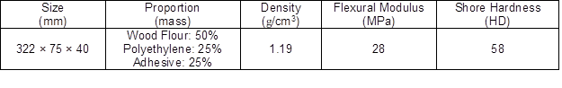
In this research, several pieces of a WPC produced by Nanjing Dayuan Plastic Wood New Material Co. Ltd. (Nanjing, China) were used. The general properties of the material are shown in Table 1.
Table 1. Properties of the WPC
Translatable carbide cutting tools manufactured by Zhuzhou Diamond Cutting Tool Co. Ltd. (Zhuzhou, China) were used to perform the test. The arbor model used was EMP01-020-G20-AP11-02. The blades used in the test were an ordinary carbide blade with a grade of YD201 and model APKT11T304-LH .The specifications of cutting tool is presented in Table 2.
Table 2. Specifications of Cutting Tool

Test Instrument
As shown in Fig. 1, cutting forces were tested by up-milling with the UCP 800 Duro five-axis machining centre manufactured by Mikron (Agno, Switzerland). The machine was equipped with an ITNC530 CNC system (Heidenhain, Berlin, Germany), laser tool (9602, BLUM, Willich, Germany), and a TC52 workpiece probe (BLUM), which can achieve tool dynamic detection and greatly improve the detection accuracy. This kind of machine not only can process and measure a workpiece synchronously, but it can also improve the repositioning accuracy of the workpiece. The maximum spindle speed and feed rate of the machine were 20000 rpm and 20 m/min, respectively, and the longitudinal travel of the X, Y, and Z axes were 850 mm, 650 mm, and 500 mm, respectively.
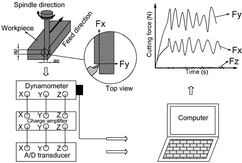
Fig. 1. The schematic diagram of cutting force measuring system
The Swiss Kistler 9257B three-way dynamometer (Winterthur, Switzerland) was used during testing, which is shown in Fig. 2. The collected electrical signal was converted to a force signal by a Kistler 5070 charge amplifier for simultaneous display in the software. The Kistler 9257B three-way dynamometer is convenient for recording the triaxial force and torque values, and automatically generates the Excel spreadsheets. The basic parameters of the Kistler 9257B three-way dynamometer are as follows: the Fx, Fy, and Fz all range from 5 kN, and the sensitivity of the Fx, Fy, and Fz was -7.5 pC/N, -7.5 pC/N, and -3.7 pC/N, respectively.
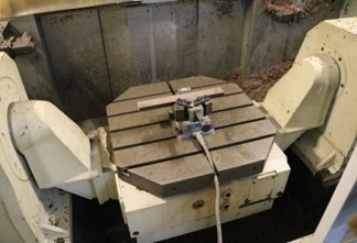
Fig. 2. Kistler 9257B three-way dynamometer installed on the machine
Testing of the Milling Force
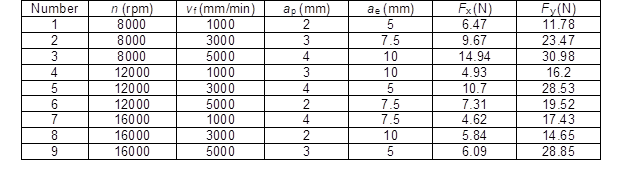
The purpose of the milling force test was to determine the influence of the milling parameters on the milling force during high-speed milling of WPCs. If the single factor method was used for testing, then the workload would be complicated, the test operation would be difficult, there would be too much test data, and the data analysis and processing would be prone to error. To achieve the same effect with fewer problems, the orthogonal test method was used in this study. The L9 (34) was used as the three-level and four-factor table with the spindle speed (n), feed rate (vf), axial milling depth (ap), and radial milling depth (ae), as is shown in Table 3. The L9 (34) orthogonal test table of the milling force is shown as Table 4.
Table 3. Orthogonal Test Factor Table of the Milling Force

Table 4. L9 (34) Orthogonal Test Table of the Milling Force
Because milling is the process of edge cutting into and out of a workpiece, the tool has an intermittent reciprocating motion. The milling edge cuts into the workpiece and away from the workpiece in the opposite direction, so that the resulting milling force is reversed. The Fx is the tangential cutting force, which is parallel to the cutting direction, and Fy is the radial cutting force, which is perpendicular to the cutting direction. Both are in the cutting plane.
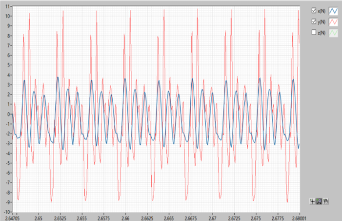
Fig. 3. Periodic variation in the milling force
In theory, their absolute values in the positive and negative directions are equal, but it was found from the measured results that their absolute value in the positive and negative directions had a certain difference and the impact was small, which may have been caused by machine vibration and other objective factors. The cyclical trends of the Fx and Fy are shown in Fig. 3. A uniform waveform was formed by median filtering. The results of this test were the final maximum values of the Fx and Fy after being filtered. Additionally, the Fz is the force parallel to the direction of the arbor. Because the tool used in this test was an indexable carbide tool, the milling edge was parallel to the axis after the blade was mounted. Therefore, there is theoretically not a cutting force in this direction, except for a weak signal caused by vibration, and thus a more in-depth study was not performed on this force.
RESULTS AND DISCUSSION
Influence of the Milling Parameters on the Milling Forces
Influence of the spindle speed on the milling forces
The results of the orthogonal test were analyzed. The average values of the Fx and Fy at different spindle speeds were calculated and the results are shown in Fig. 4.
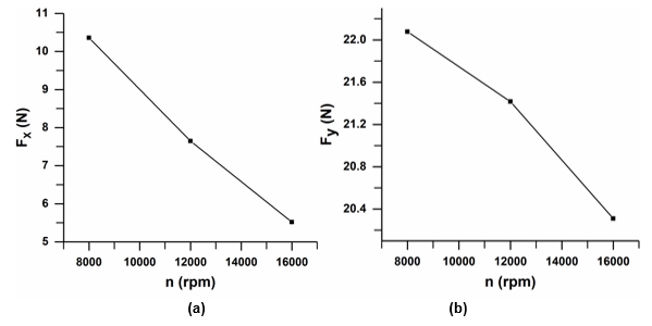
Fig. 4. Influence of the spindle speed on the (a) Fx and (b) Fy
When the spindle speed was 8000 rpm, the Fx and Fy were both the highest, and when the spindle speed increased to 16,000 rpm, the Fx and Fy both achieved minimum values. The results showed that the Fx and Fy gradually decreased with an increase in the spindle speed and the changing trend was close to a straight line, which indicated a slight relationship between the milling force and spindle speed. The increase in the spindle speed resulted in a decrease in the feed per revolution under the same conditions, which caused a decrease in the average milling thickness per unit time. The cutting deformation caused by the workpiece material and the power required in the single cutting time were reduced; therefore, the total milling force was reduced. It was also found from Fig. 4 that the Fx was smaller than the Fy, but the change trend of the Fx was more obvious than that of the Fy.
Influence of feed rate on milling forces
The average values of the tangential force Fx and the radial force Fy at different feed rates were also calculated. The results are shown in Fig. 5. It was found that when the feed rate was increased from 1000 mm/min to 3000 mm/min and to 5000 mm/min, both Fx and Fy were gradually increased. This shows that the impact of feed rate on the milling forces was relatively large, and the changing trends of Fx and Fy increased rapidly and then increased slowly, but the trend for Fx was more obvious. This is mainly because when feed rate increases from 1000 mm/min to 5000mm/min, feed peer revolution increases from 0.09 mm/rev to 0.45 mm/rev, which means more materials being cut per unit time. In other words, the required load that the material produces plastic and elastic deformation was larger when the average thickness of the milling was higher, which results in the need for more energy to disengage the chips from the workpiece.
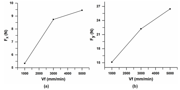
Fig. 5. Influence of the feed rate on the (a) Fx and (b) Fy
Influence of the axial depth on the milling forces
It was mentioned above that the change in the spindle speed and feed speed had a certain effect on the Fx and Fy. The reason was that the change in the spindle speed and feed rate resulted in a change in the average cutting thickness during milling. The axial cutting depth represents the cutting thickness. Figure 6 shows that the Fx and Fy tended to increase gradually when the axial depth increased from 2 mm to 3 mm and then to 4 mm. The Fx first slowly increased and then rapidly increased, while the Fy behaved in the opposite manner and rapidly increased at first and then slowly increased. This showed that the axial depth had a major impact on the milling force. The main reason was that the cutting zone area increased with an increase in the cutting thickness, which increased the deformation resistance of the workpiece material. Because of the increase in the deformation resistance of the workpiece material, a greater deformation force was needed when the chip is away from the material matrix. Additionally, the internal friction between the cutting edge and workpiece surface to be machined increased, which increased the total milling force.
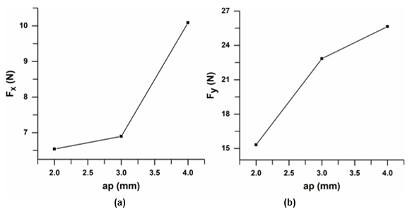
Fig. 6. Influence of the axial depth on the (a) Fx and (b) Fy
Influence of the radial cutting depth on the milling forces
Figure 7 shows that the Fx and Fy first decreased and then increased when the radial milling depth increased from 5 mm to 7.5 mm and then further increased to 10 mm, but the magnitude of the change was relatively small. The maximum and minimum values differed by only 2 N to 3 N for both the Fx and Fy. The influence of the radial milling depth on the milling forces was not obvious compared with the other factors (spindle speed, feed rate, and axial cutting depth). Thus, it was concluded that the radial milling depth had little effect on the milling forces.
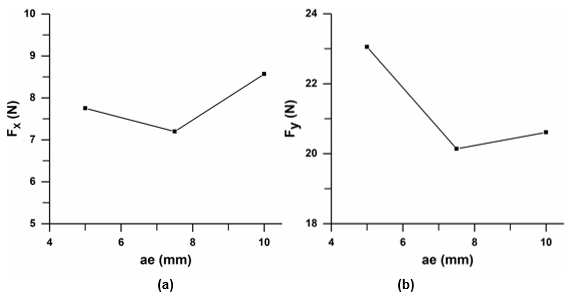
Fig. 7. Influence of the radial cutting depth on the milling forces: (a) Fx and (b) Fy
Analysis of the Milling Forces and Mathematical Models
One-dimensional linear regression has one major influencing factor as an independent variable to explain the variation in the dependent variable. One factor is changed to study the changes in the results, while keeping the other factors unchanged. This is a single factor test method and it studies the basic principles of practical problems (Kakosyan 1979; de Carvalho et al. 2004). However, for practical problems, a change in the dependent variable will be affected by more than one important factor. Multiple regression allows for more influential factors to be independent variables to explain the variation in the dependent variable (Lorenzo-Seva and Ferrando 2011; Schinazi 2011). The purpose of this test was to use the orthogonal test method to study the influence of the four important parameters (n, vf, ap, and ae) on the milling forces (Fx and Fy). The analysis of the previous test results showed that three of the four factors (n, vf, and ap) had a remarkable effect on the Fx and Fy, and the results showed that the dependent variables Fx and Fy were substantially and linearly related to them. Multiple linear regression analysis was required to study the relationship between the variables. This analysis obtained a mathematical model function between the dependent variable and independent variables. The SPSS Statistics software was used to perform the regression analysis in this research (23th version , IBM, Northampton, United States).
Significance analysis and mathematical model of the Fx
According to the principle of multiple linear regression analysis used in this test, formulas for the Fx and Fy were obtained and are expressed by Eqs. 1 and 2, respectively.
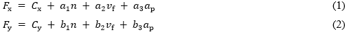
where Fx is the tangential milling force (N), Fy is the radial milling force (N), Cx and Cy are the correction coefficients of the tangential and radial forces, respectively, n is the spindle speed (rpm), vf is the feed rate (mm/min), and ap is the axial milling depth (mm).
By using the SPSS Statistics software to conduct a multiple linear regression analysis on the orthogonal test results of the milling forces, valuable results were obtained. As shown in Table 5, Adjusted R2 of Fx model was 0.811, which indicated that the independent variables of the model can explain the dependent variable well and the fitting degree is very good.
Table 5. Model Summary of the Fx Model

Table 6 shows the variance analysis of the Fx model. It was found that the sum of squares of the regression accounted for most of the total and the residual square sum was only a small portion. The significance was 0.009, which showed that the Fx model is significant and credible.
Table 6. ANOVA Analysis of the Fx Model

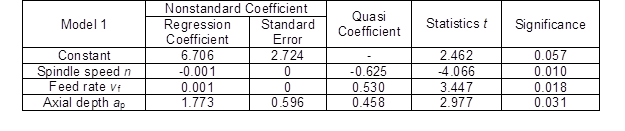
Table 7 gives the regression coefficients for the Fx model. The constant was 6.706, the spindle speed coefficient was -0.001, the feed rate coefficient was 0.001, and the coefficient of the axial cutting depth was 1.773. The multiple linear regression equation of the Fx is shown as Eq. 3
![]()
Table 7. Regression Coefficients for the Fx Model
Significance analysis and mathematical model of the Fy
Adjusted R2 of Fy model was 0.876 (Table 8), which indicated that the independent variables of the model can explain the dependent variable well and the fitting degree is very good.
Table 8. Model Summary of the Fy Model

Table 9 shows the variance analysis of the Fy model. The sum of squares of the regression accounted for most of the total and the residual square sum was only a small portion. The significance was 0.003, which indicated that the Fy model is also significant and credible.
Table 9. ANOVA Analysis of the Fy Model

Table 10. Regression Coefficients for the Fy Model
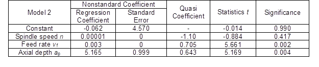
Table 10 gives the regression coefficients of the Fy model. The constant was -0.062, the spindle speed coefficient was 0.00001, the feed rate coefficient was 0.003, and the coefficient of the axial cutting depth was 5.165. The multiple linear regression equation of the Fy is shown as Eq. 4.
![]()
CONCLUSIONS
When a wood-plastic composite (WPC) is milled at high speeds, the forces Fx and Fy are affected by the milling parameters, but the Fz is mostly unaffected.
In high-speed milling, high speed and low feed can be selected to reduce the feed per revolution to reduce the cutting force. In addition, the small axial milling depth and the large radial milling depth reduce the milling force while maintaining the same average milling area.
Based on the multivariate linear regression analysis of the orthogonal test results, multivariate linear regression equations of the Fx and Fy in the high-speed milling of WPCs were established (Eqs. 3 and 4).
The variance analysis results showed that the two models were significant. The two equations can be used to accurately predict the Fx and Fy under different milling parameters, which can provide a reliable theoretical basis for actual milling.
ACKNOWLEDGMENTS
The authors are grateful for the financial support from the Open Fund for Jiangsu Key Laboratory of Advanced Manufacturing Technology (HGAMTL-1605), the Joint Training Demonstration Base Construction Project for Professional Degree Graduate in Nanjing Forestry University (2017JD01), the Course Case Library Construction Project for Professional Degree Graduate in Nanjing Forestry University (2017AL08), Jiangsu “Six Talent Peak” Project (JXQC-022), and Jiangsu Overseas Research & Training Program for University Prominent Young & Middle-aged Teachers and Presidents.
REFERENCES CITED
Byrne, G., Dornfeld, D., and Denkena, B. (2003). “Advancing cutting technology,” CIRP Ann.-Manuf. Techn. 52(2), 483-507. DOI: 10.1016/S0007-8506(07)60200-5
Darmawan, W., Tanaka, C., Usuki, H., and Ohtani, T. (2001a). “Performance of coated carbide tools when grooving wood-based materials: effect of work materials and coating materials on the wear resistance of coated carbide tools,” Journal of Wood Science 47(2), 94-101. DOI: 10.1007/BF00780556
Darmawan, W., Tanaka, C., Usuki, H., and Ohtani, T. (2001b). “Performance of coated carbide tools in turning wood-based materials: Effect of cutting speeds and coating materials on the wear characteristics of coated carbide tools in turning wood-chip cement board,” Journal of Wood Science 47(5), 342-349. DOI: 10.1007/BF00766783
Darmawan, W., and Tanaka, C. (2004). “Discrimination of coated carbide tools wear by the features extracted from parallel force and noise level,” Annals of Forest Science 61(7), 731-736. DOI: 10.1051/forest:2004070
de Carvalho, F. d. A. T., Neto, E. d. A. L., and Tenorio, C. P. (2004). “A new method to fit a linear regression model for interval-valued data,” in: KI 2004: Advances in Artificial Intelligence, S. Biundo, T. Frühwirth, and G. Palm (eds.), Springer Berlin Heidelberg, Berlin, Germany, pp. 295-306.
Đurković, M., Mladenović, G., Tanović, L., and Danon, G. (2018). “Impact of feed rate, milling depth and tool rake angle in peripheral milling of oak wood on the cutting force (AOP Paper),” Maderas. Ciencia y Tecnologia 20(1), 25-34. DOI: 10.4067/S0718-221X2018005000003
Kakosyan, A. V. (1979). “Theory of estimation of parameters in a linear regression scheme,” Journal of Soviet Mathematics 12(2), 227-237. DOI: 10.1007/BF01262721
Kılıç, M., Burdurlu E., Aslan S., Altun S., and Tümerdem, Ö. (2009). “The effect of surface roughness on tensile strength of the medium density fiberboard (MDF) overlaid with polyvinyl chloride (PVC),” Materials and Design 30, 4580-4583. DOI: 10.1016/j.matdes.2009.03.029
Lorenzo-Seva, U., and Ferrando, P. J. (2011). “ FIRE: An SPSS program for variable selection in multiple linear regression analysis via the relative importance of predictors,” Behaior Research Methods 43(1), 1-7. DOI: 10.3758/s13428-010-0043-y
Schinazi, R. B. (2011). Probability with Statistical Applications, Birkhäuser, Boston, MA.
Wei, W., Xu, J., Fu, Y., and Yang, S. (2012). “Tool wear in turning of titanium alloy after thermohydrogen treatment,” Chinese Journal of Mechanical Engineering 25(4), 776-780. DOI: 10.3901/CJME.2012.04.776
Wei, W., Li, Y., Xue, T., Tao, S., Mei, C., Zhou, W., Wang, J., and Wang, T. (2018). “The research progress of machining mechanisms in milling wood-based materials,” BioResources 13(1), 2139-2149. DOI: 10.15376/biores.13.1.2139-2149
Article submitted: June 27, 2018; Peer review completed: August 10, 2018; Revised version received and accepted: November 25, 2018; Published: December 6, 2018.
DOI: 10.15376/biores.14.1.769-779