
Abstract
In various engineering applications, self-tapping screws are used to connect timber members. To describe their load-deformation relationship, a better understanding of the strain along the mechanical interface (i.e., timber-screw interface) is required. With a focus on the axial loading of self-tapping screws, only a few studies have dealt with the determination of the strain based on optical measurement techniques. Therefore, in the present study, the strain distribution at the timber-screw interface was monitored during pull-out tests using an optical measurement technique, called electronic speckle pattern interferometry (ESPI). Strains obtained from the ESPI measurements were compared with the results obtained from structural simulations conducted with finite element modelling (FEM). Three different types of solid spruce wood (Picea abies (L.) Karst.) specimens with different grain orientations connected with self-tapping screws (thread length lg = 130 mm, outer thread diameter d = 12 mm) were tested in withdrawal. There was a good agreement between the ESPI and FEM results, confirming that ESPI was a suitable measurement technique. The study also provided insights and results regarding the region of strain concentrations across the length of self-tapping screws.
Download PDF
Full Article
Timber Screw Connection: Study of the Strain along the Interface Using Optical Measurement Techniques and Simulations
Cedou Kumpenza,a,* Andreas Ringhofer,b Thomas Krenke,c Adeayo Sotayo,d Maximilian Pramreiter,a and Ulrich Müller a
In various engineering applications, self-tapping screws are used to connect timber members. To describe their load-deformation relationship, a better understanding of the strain along the mechanical interface (i.e., timber-screw interface) is required. With a focus on the axial loading of self-tapping screws, only a few studies have dealt with the determination of the strain based on optical measurement techniques. Therefore, in the present study, the strain distribution at the timber-screw interface was monitored during pull-out tests using an optical measurement technique, called electronic speckle pattern interferometry (ESPI). Strains obtained from the ESPI measurements were compared with the results obtained from structural simulations conducted with finite element modelling (FEM). Three different types of solid spruce wood (Picea abies (L.) Karst.) specimens with different grain orientations connected with self-tapping screws (thread length lg = 130 mm, outer thread diameter d = 12 mm) were tested in withdrawal. There was a good agreement between the ESPI and FEM results, confirming that ESPI was a suitable measurement technique. The study also provided insights and results regarding the region of strain concentrations across the length of self-tapping screws.
Keywords: Electronic speckle pattern interferometry; Finite-element modelling; Norway spruce; Optical measurement technique; Pull-out test; Self-tapping screw; Solid timber; Strain measurement
Contact information: a: Institute of Wood Technology and Renewable Materials, Department of Material Science and Process Engineering, University of Natural Resources and Life Sciences Vienna (BOKU), Konrad-Lorenz-Strasse 24, A-3430 Tulln an der Donau, Austria; b: Institute of Timber Engineering and Wood Technology, Graz University of Technology, Inffeldgasse 24, A-8010 Graz, Austria; c: Innovationszentrum W.E.I.Z., Franz-Pichler-Straße 30, A-8160 Weiz, Austria; d: College of Engineering, Design and Physical Sciences, Department of Design, Brunel University London, Michael Sterling Building MCST156, Kingston Lane, Uxbridge, UB8 3PH, London, England;
* Corresponding author: cedou.kumpenza@boku.ac.at
INTRODUCTION
At the beginning of the automotive industry, timber was commonly used as load-bearing components in vehicles (Braess and Seiffert 2013). In the following decades, timber was replaced by metals, due to the growth of the steel industry. However, ongoing research projects like “Wood C. A. R.”, “For(s)tschritt”, and the “NCV – Project” focus on the reintroduction of timber and timber composites as structural elements in vehicles again (Kohl et al. 2016; Müller et al. 2019). One of the reasons for these initiatives is that the use of novel multi-layer materials (e.g., sandwich structures) that contain timber has the potential to significantly reduce weight and therefore decrease the energy consumption of vehicles. To connect timber elements with the surrounding vehicle parts, the use of self-tapping screws is an economical and reliable mechanical fastening solution. The main advantages of self-tapping screws compared to pins, threaded rods, and bolts, are the ease of installation (no pre-drilling is needed) and the possibility to use them in other applications such as tensile joints, butt joints, etc. (Trautz and Koj 2009; Dietsch and Brandner 2015; Ringhofer 2017). Still, mechanically stable and durable bonds of self-tapping screws joined with timber are needed to guarantee the safety requirements for their applications. Especially for predominantly axially loaded screws, the stress-strain distribution around the timber-screw joint area is related to the withdrawal behavior of the screw. Therefore, it is important to investigate the strain distribution of such embedded screws, which are loaded axially by applying non-contact measurement techniques. In particular, the observed deformations and strains are essential features for developing a better understanding of the axial withdrawal failure mode of the timber-screw connection. Currently, the estimation of the withdrawal capacity, Fax, α, Rk is obtained from simple, empirical regression models, as recommended in Eurocode 5 of EN 1995-1-1 (2015) for the design of screwed connections in timber structures. The fitting parameters in these models are continuously adjusted and determined due to stochastic-empirical investigations (Wilkinson and Laatsch 1970; Eckelman 1975; Gustafsson et al. 2001; Frese et al. 2010; Jensen et al. 2011; Ringhofer et al. 2015; Perçin 2016; Brandner et al. 2019; Du et al. 2019). This is expensive and time-consuming. Moreover, these investigations did not provide a sufficient structural understanding of the mechanics happening at the timber-screw interface.
The estimation of the withdrawal capacity using computer-based numerical investigations, such as finite element modelling (FEM), is another approach, which is scarcely described in the literature. On the one hand, applying FEM for the estimation of the withdrawal capacity of timber-screw connections is highly complex, because of the morphological changes in the wood (densified and damaged wood cell) around the vicinity of the screw, which is difficult to predict and to describe properly. In contrast, FEM also demands experimental results to verify the numerical simulations (Fueyo et al. 2009; Steilner 2014; Hochreiner et al. 2016; Füssl et al. 2017). Electronic speckle pattern interferometry (ESPI), for instance, provides full-field optical strain data with a high-measurement resolution that can be used to capture close-up strain maps along the mechanical timber-screw interface. Results from these types of experiments are essential for analyses and validation purposes when FEM is performed.
Ellingsbø and Malo (2012), Ayoubi and Trautz (2013), Ayoubi (2014), and Trautz (2017) established strain distribution around self-tapping screws joined with timber using a full-field optical gauging technique, namely digital image correlation (DIC) during screw pull-out tests. The DIC can provide full-field visualized strain data that considers a high accurate field of view (FoV) as required to monitor the timber-screw interface. Ayoubi and Trautz (2013) found good correlation of the DIC results compared to the measurements conducted with surface-bonded resistive strain gauges, and the experiments measured with local linear variable differential transformers (LVDT). Nevertheless, in all these research studies, the strain distribution of the outer timber-specimen surface was observed, whereas the screw was embedded in the core of the timber. That means that the screws were surrounded completely by the timber element, which meant that the timber-screw interface could not be closely monitored with the consequence that the strains at the interface were assumed without having direct measurements results. Therefore, the aim of this study was to capture the strains along and close to the timber-screw interface, subject to axial loading. A pull-out experiment was designed to allow direct strain measurements along the interface using the full-field optical gauging technique, ESPI. Previous studies have shown that ESPI is suitable to measure strain distribution of highly heterogeneous and anisotropic materials like wood in the micro- or nano-scale (Eberhardsteiner 1995; Valla et al. 2011; Kumpenza et al. 2018).
The hypothesis of this study was that high resolution full-field optical gauging techniques can give insights into the strain distribution along the mechanical timber-screw interface. It was believed that the experimental results of this research study can be used for future screw developments and for validation purposes of computer-based numerical simulations. For that reason, the ESPI measurements were analyzed and compared with established and validated simulation results.
EXPERIMENTAL
Materials
Test-samples
The material used for the specimens was Norway spruce (Picea abies (L.) Karst.) (sourced from J. u. A. Frischeis GmbH, Stockerau, Austria). Randomly selected timber logs were processed by means of a circular saw and a planning machine. After finishing the timber elements to the desired dimensions of 200 mm × 240 mm × 200 mm (width × height × length), the samples were conditioned at a temperature of 20 ± 2 ℃ and a relative humidity of 65 ± 5% to an average moisture content of ≈ 12%. The average sample density m was 362 ± 14 kg/m3. For the purpose of image capturing, the samples were cut into two halves, clamped together with screw clamps, and the self-tapping screws were inserted in the center of the samples without drilling pilot holes. Before performing the pull-out experiments, one half was removed carefully so that the screw was exposed, as shown in Fig. 1.

Fig. 1. (a) Illustration of the specimen RL including the investigated field of views (FoV-1= 40 mm × 70 mm and FoV-2 = 100 mm × 125 mm) and (b) finite-element model of the specimen
In total, three different configurations were tested, i.e., screw insertion in wood grain direction and perpendicular to the wood grain direction with a field of view (FoV-1 and FoV-2) on the specimen surface planes longitudinal-radial (LR), radial-longitudinal (RL), and tangential-radial (TR), as illustrated in Fig. 1a. In order to improve the measurement capability, the surface of the screw of the specimen LR was carefully sanded (heat development was avoided) so that it had the same level as the timber element. With this additional procedure it was assumed that more accurate measurements could be performed because the surface of the specimen was flat. Due to the complexity of this procedure and no further improved measurement results, this procedure was not applied on the other specimens. For the numerical simulation, a finite element model was designed (Fig. 1b) and evaluated with different material properties (cf. section: “Description of the simulation model”).
Self-tapping screws
The partially threaded self-tapping screw: “ASSY (Adolf Würth GmbH and Co. KG, Künzelsau, Germany)” with a (nominal) outer thread diameter of d = 12 mm and a (nominal) inner thread diameter of d1 = 7.2 mm was used for the experiments. The complete thread length of lg = 130 mm was inserted into the timber, so that it was feasible to investigate a large timber-screw interface. According to the technical approval ETA-11/0190 (ETA-11/0190 2013), the screw has a characteristic tensile capacity of ftens,k = 45 kN, a yield moment of My,k = 58 Nm, and a modulus of elasticity of Es = 210 GPa.
Methods
Experimental set-up
The pull-out experiments (Fig. 2) were performed on the universal testing machine Zwick/Roell Z100 (Zwick GmbH & Co. KG, Ulm, Germany), equipped with a 100 kN load cell and the control software Zwick/Roell testXpert Ⅱ V3.5 (Zwick GmbH & Co. KG, Ulm, Germany).

Fig. 2. Test set-up of the screw pull-out experiments
The specimens were clamped between a steel beam and the testing machine, so that pulling the screw occurred without any movement of the timber member. Due to the appearing tensile forces, the timber member was pressed against the steel beam and the screw was pulled-out. To ensure that the test occurred in the elastic phase, the maximum applied load was 20% of the theoretical characteristic withdrawal capacity Fax, α, Rkexp. The withdrawal capacity was calculated using Eurocode 5 of EN 1995-1-1 (2015), which is shown below,
Fax, α, RKexp = Fax, α, Rk / 2 (1)
Fax, α, Rk = (nef × fax,k × d × lef × kd) / (1.2 × cos2(α) + sin2(α)) (2)
fax,k = 0.52 × d-0.5 × lef-0.1 × ρk0.8 (3)
kd = min (4)
where nef is the effective number of used screws. The fax, k is the characteristic value of the withdrawal strength, which depends on the outer thread diameter d (mm), the penetration length of threaded part lef (in this case lef = lg), and the characteristic density k = 347 kg/m3, which is the 5% percentile of m of the timber. The kd describes a reduction factor that must be applied for screws with an outer thread diameter of d ≤ 8 mm. The angle of the screw axis to grain direction is also needed and defined by the parameter which were either 0° or 90°. The experimental tests were conducted at a crosshead speed of 5 mm/min. Further, applying low forces indicated that the out-of-plane motion was expected to be low enough to be negligible. Pre-tests and simulations also confirmed that assumption.
Table 1. Experimental Parameters

ESPI technique
The ESPI (Q300 ESPI System; Dantec-Ettemeyer, Ulm, Germany) is a non-contact full-field optical gauging technique, which was used to capture the planar strain distribution around the timber-screw interface. The ESPI provides high-resolution deformations so that the deformation of heterogeneous and anisotropic materials such as wood can be detected (Valla et al. 2011; Kumpenza et al. 2018). Detailed descriptions with the basic principle of the ESPI technique are given by several authors (Eberhardsteiner 1995, Jones and Wykes 1989; Gingerl 1998; Schmidt et al. 2003; Martinez et al. 2004; Müller et al. 2005; Hagara et al. 2016). In short, for in-plane measurements (movements in x- and z-axis) the sample surface is illuminated from two different planar directions with a laser beam, and the superposition of both reflected light waves forms a speckle pattern (resulting interference distribution), which is registered by a CCD camera as illustrated in Fig. 3.
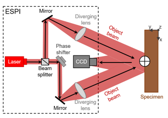
Fig. 3. ESPI set-up for in-plane measurements (schematic drawing based on Müller et al. 2005)
The intensity distribution of the speckle pattern image can be described with the following equation,
I(u,v) = I0(u,v) × [1 + ![]() (u,v) × cos(
(u,v) × cos(![]() (u,v))] (5)
(u,v))] (5)
where (u,v) were the coordinates on the CCD chip, I0 is the intensity of the laser beam, ![]() described the contrast function and
described the contrast function and ![]() the phase of the laser beam front. Surface movements caused by mechanical loading led to new phase differences between the reflected light waves and thus to new speckle pattern images, which were stored by a computer. Subtracting the upcoming speckle pattern image from the initially captured image gives rise to an image with typical fringe pattern, in which points along the fringes correspond to lines of constant displacement in the direction of the defined sensitivity vector (Müller et al. 2005). This image with a typical fringe pattern was transformed into a map of displacement after applying a temporary phase-shift method (An and Carlsson 2003). Finally, through post-processing, a map of strain distribution was derived. One to ten fringes had been proved to be appropriate for ESPI measurements, which means that for higher loads the experiment has to be divided into several load steps (Müller et al. 2015).
the phase of the laser beam front. Surface movements caused by mechanical loading led to new phase differences between the reflected light waves and thus to new speckle pattern images, which were stored by a computer. Subtracting the upcoming speckle pattern image from the initially captured image gives rise to an image with typical fringe pattern, in which points along the fringes correspond to lines of constant displacement in the direction of the defined sensitivity vector (Müller et al. 2005). This image with a typical fringe pattern was transformed into a map of displacement after applying a temporary phase-shift method (An and Carlsson 2003). Finally, through post-processing, a map of strain distribution was derived. One to ten fringes had been proved to be appropriate for ESPI measurements, which means that for higher loads the experiment has to be divided into several load steps (Müller et al. 2015).
Strain measurement using ESPI
To improve the signal to noise ratio of ESPI measurements, the investigated specimen surface was colored with a matt white spray paint (Werkstoffprüfung HÖDL GmbH, Wels, Austria) before the screw pull-out tests were conducted. The ESPI focus was adjusted on the screw axis. Depending on the specimen, different maximal load forces (Fmax) were calculated using Eqs. (1 to 4). The maximum load (Fmax) was applied step-by-step in each pull-out test, so that image capturing could be performed correctly. In addition, special care had to be taken to guarantee that the timber elements had no movements at all during image capturing. This was because additional movements in the specimens can affect ESPI measurements. In this case, the crosshead movement of the universal testing machine was stopped for 5 s at every load step, while the image was captured. The load steps were chosen based on a preliminary study that showed that the induced fringes would give exploitable deformation images, which is needed to calculate consistent strain maps. The total specimen deformation within the field of view (FoV-1 and FoV-2) was established by adding up the images of each load step using the ESPI software ISTRA 2001 (Dantec-Ettemeyer, Ulm, Germany). Afterwards, the in-plane strains, i.e., axial strain (εy), transverse strain (εx), and shear strain (γxy), were calculated by differentiating the deformation images in the horizontal and vertical directions as described in Müller et al. (2015). Due to the high sensitivity of ESPI devices, it was necessary to mount the device with an additional supporting frame on the universal testing machine in a way that no lateral movements or vibrations of the device were possible. In addition, a preload (Fv) was always applied before starting the pull-out experiments to stabilize the specimens. The device Q300 (Dantec-Ettemeyer, Ulm, Germany) provided a maximal measurement resolution of 0.03 µm (Dantec Dynamics A/S 2017), which was necessary to capture precise close-up images within the chosen field of view of FoV-1 = 40 mm × 70 mm and FoV-2 = 100 mm × 125 mm (width × height)
Description of the simulation model
A three-dimensional finite element model (3D-FE) of the test samples (Fig. 1b) was designed and developed with Nastran In-CAD V.2019.2 (Autodesk, Mill Valley, CA, USA). Timber was modelled as a solid orthotropic material (MAT12) with linear-elastic material parameters, whilst the screw was assumed as an isotropic material (MAT1). A linear- static analysis was chosen for simulation, which meant that only elastic deformations were considered. Based on the designed experimental set-up, no plastic deformations could occur, and therefore this assumption was made. Various literature (Kollmann 1968; Neuhaus 1981; Keunecke et al. 2008; Dahl and Malo 2009; Müller et al. 2015; Ringhofer 2017; Niemz and Sonderegger 2017) were considered to find suitable material parameters for the stiffness matrix [C], which includes Young’s moduli (x, y, and z), Poisson’s ratios (xy, zx, and zy), and shear moduli (Gxy, Gzx, and Gzy). The simulation model parameters are summarized in Table 2.
Table 2. Simulation Model Parameters

Depending on the investigated test configuration (LR, RL, or TR), the coordinate system of the specimen was rearranged to simulate the corresponding timber orientation. The contact condition between timber and screw was set to “separation”, so that sliding as well as the opening was possible. Analogous to the experiments (Fig. 2), the upper surface of the specimen was constrained in all six directions for translation (Tx, Ty, and Tz) and rotation (Rx, Ry, and Rz). For the simulations, the preload (Fv) and the maximal load (Fmax) were applied in a single step. The forces were applied at the borderline between the screw head and shaft in the global z-direction. The mesh was generated using the automatic mesh generator included in Nastran In-CAD V.2019.2 software (Autodesk, Mill Valley, CA, USA). General mesh size for the specimen was 8 mm and 4 mm for the screw. The maximum element growth rate was set to 1.25 mm and element shape was set to tetrahedron. Additionally, three different mesh controls were applied. The first mesh control (1-mm element size) was applied on the surface of the specimen, covering the area from the screw shaft 11.4 mm outwards and over the whole screw length downwards. The second mesh control (0.3 mm) was used to approximate the mesh size at the threads between the screw and the specimen. The third mesh control (1.5 mm) was applied to the specimen at the interphase between the screw shaft and specimen borehole. The general aim of the model was to replicate the deformations obtained through laboratory tests. This should provide further insights into the plausibility of the laboratory results.
RESULTS AND DISCUSSIONS
Figure 4 shows an overview of all established in-plane strains, i.e., axial strain (εy), transverse strain (εx), and shear strain (γxy), within the chosen field of view of FoV-1 = 40 mm × 70 mm across the timber-screw interface. For each test configuration (cf. Tables 1 and 2) the ESPI and FEM results are presented in false colors (colors that differ from the natural color impression). The displayed false colors describe the full-field strain distribution, whereby the red color represents a positive strain value and dark blue a negative strain value. Due to the use of false colors, fine deviations are clearly distinguishable. Independent of the specimen, a characteristic strain distribution was obtained for all three strain maps, which also reflected the specific geometry of the timber-screw interface. As expected, at the interface, strain concentrations were detected for all three strain components. The relatively low stiffness of spruce wood, i.e., modulus of elasticity of EL = 10 to 14 GPa, ER = 0.6 to 1 GPa, and ET = 0.4 to 0.5 GPa in the longitudinal, radial, and tangential directions, respectively, compared to the stiffness of the screw of ES = 210 GPa, leads to compression and expansion of the wood material in the range of -5‰ to +5 ‰. In the axial direction, the strain concentrations (εy) around the screw thread were alternating from negative to positive values over the complete screw length (Fig. 4a, 4b, and 4c). Moreover, the axial strains (εy) have an “arch-shaped” form that was influenced by the thread geometry of the inserted screws. Compression and expansion of the wood material appeared mainly above and beneath the thread flanks, which led directly to the pronounced local axial strain concentrations around the screw-thread. Applying ESPI for the strain measurement has enabled the visualization and measurement of this phenomenon.
Even though the applied forces differed between the configurations, a higher intensity of the axial strain (εy) for the specimen with screw insertion perpendicular to the wood grain direction (Fig. 4b and 4c) compared to the specimen with screw insertion in the wood grain direction (Fig. 4a) can be observed. High material stiffness (EL > ER and EL > ET) means low capacity of material deformation, but at the same time high capability of stress transmission, which could also explain the relatively high stresses that can be transmitted in the axial direction for the specimen LR (Ez = EL) and in transverse direction for the specimen RL (Ex = EL). Regarding the transverse strain (εx), a high concentration at the screw insertion point was observed that decreased dramatically until the screw tip was reached (Fig. 4d, 4e, and 4f). Compared to that, the shear strains (Fig. 4g, 4h, and 4i) were nearly evenly distributed over the screw penetration length.
The FEM results illustrated that on a qualitative level, the simulation depicted the results of the pull-out experiments quite well (Fig. 4), which also confirmed that ESPI was suitable to capture the micro mechanical deformations. However, the quantitative validation of the experiments with the simulations showed that they were partly deviations in the simulated results, in comparison with the experimental observations. Several reasons might lead to these deviations. For example, the simulation model did not consider material densification and damages that were caused due to inserting the screw into the timber. Especially in the vicinity of the screw, these changes in the timber material would have an influence on the strain behavior during the pull-out tests. Furthermore, compared to the simulations, the strains derived from the experiments did not follow the same calculation principle. On the one hand the strains were derived from highly accurate and sensitive deformation measurements, and in the other hand, there were numerical calculations that were dependent on the applied material model and properties (based on Hooke’s law). Small continuation errors occurred in the calculation because the literature values were used for the material models (MAT1, MAT12) that could have led to these deviations. Another influencing factor could be the element-size of the simulation model, which exceeded the occurring deformations at the mechanical timber-screw interface. Using smaller elements would lead to high computing time.

Fig. 4. ESPI and FEM strain maps (![]() y,
y, ![]() x, and
x, and ![]() xy) within the observed field of view of FoV-1 = 40 mm × 70 mm of the specimens LR, RL, and TR
xy) within the observed field of view of FoV-1 = 40 mm × 70 mm of the specimens LR, RL, and TR
To better understand the mechanics along the interface section, minimal and maximal strains (![]() ymin(LR),
ymin(LR), ![]() ymax(LR),
ymax(LR), ![]() xmin(LR),
xmin(LR), ![]() xmax(LR),
xmax(LR), ![]() xymin(LR), and
xymin(LR), and ![]() xymax(LR)) of the specimen LR were plotted over the penetration length (lp) of the inserted screw (Fig. 5). All strains showed a curve progression that had at the screw insertion point the highest amplitudes that decreased over the penetration length. Ellingsbø and Malo (2012) and Trautz (2017) also reported an inhomogeneous stress-strain distribution over the screw length with a maximum at the screw insertion point, even though the timber-screw interface was not investigated. Moreover, it must be taken into account that applying full-field optical gauging techniques like DIC and ESPI always means that the object surface is described as a speckle pattern image that is subsequently used to create a map of deformation of the investigated surface (Jones and Wykes 1989; Zink et al. 1995). Consequently, investigating a surface that was far away from the stressed volume led to a noticeable underestimation of the true expected deformations and strains. Thus, regarding the results established in Ellingsbø and Malo (2012), Ayoubi and Trautz (2015), Ayoubi (2014), and Trautz (2017), this effect has to be considered, especially when there is a need to make a statement about the upcoming strain-stress distributions at the mechanical timber-screw interface.
xymax(LR)) of the specimen LR were plotted over the penetration length (lp) of the inserted screw (Fig. 5). All strains showed a curve progression that had at the screw insertion point the highest amplitudes that decreased over the penetration length. Ellingsbø and Malo (2012) and Trautz (2017) also reported an inhomogeneous stress-strain distribution over the screw length with a maximum at the screw insertion point, even though the timber-screw interface was not investigated. Moreover, it must be taken into account that applying full-field optical gauging techniques like DIC and ESPI always means that the object surface is described as a speckle pattern image that is subsequently used to create a map of deformation of the investigated surface (Jones and Wykes 1989; Zink et al. 1995). Consequently, investigating a surface that was far away from the stressed volume led to a noticeable underestimation of the true expected deformations and strains. Thus, regarding the results established in Ellingsbø and Malo (2012), Ayoubi and Trautz (2015), Ayoubi (2014), and Trautz (2017), this effect has to be considered, especially when there is a need to make a statement about the upcoming strain-stress distributions at the mechanical timber-screw interface.

Fig. 5. Progression of the minimal and maximal strains (εy, εx, and ![]() xy) over the penetration length of the specimen LR within the field of view of FoV-2 = 100 mm × 125 mm
xy) over the penetration length of the specimen LR within the field of view of FoV-2 = 100 mm × 125 mm
Looking at the transverse strain (εx) and shear strain (γxy) it is also important to identify the affected region in the wood, because the interaction of transverse and shear stresses is the major reason for failure in the timber-screw connection. For example, the timber material edge or a second screw axis is placed close to the screw, stresses cannot subside into the surrounding material completely, and the calculated load-carrying capacity might not be achieved. The specimen LR showed a high strained region with a total width of w (LR) = 22 mm, RL a region with a total width of w (RL) = 19 mm, and for TR a region with a total width of w (TR) = 18 mm. The captured regions were far below the design recommendations of Eurocode 5, which said that from the screw axis to the timber edge, there should be a minimum distance of a1, CG = 10 × d (= 120 mm) for screws inserted in the wood grain direction or rather a2,CG = 4 × d (= 48 mm) for screws inserted perpendicular to the wood grain direction. The minimum distance from screw axis to screw axis is defined in Eurocode 5 with a1 = 7 × d (= 84 mm) and a2 = 5 × d (= 60 mm) in the wood grain direction and perpendicular to the wood grain direction, respectively. In this context, it must be mentioned that the recommended screw distances in Eurocode 5 also considered splitting effects that can occur while the self-tapping screws were inserted (no pilot holes) into the timber material. Therefore, a direct comparison of the screw distances (a1, a2, a1 CG, and a2 CG) to the measured values (w (LR), w (RL), w (TR)) was possible only to a limited extent, because in this study the affected wood material region in consequence of screw pull-out was analyzed without observing the screw insertion mechanisms.
The observation of the strain maps of the simulation underlined the necessity to use correct and accurate elastic material parameters ([C]) to establish precise results, especially in the vicinity of the screw. In this study, these elastic material parameters ([C]) were taken from literature corresponding to the measured average specimen density m, as there is a known correlation between elastic wood material properties and wood density (Gibson et al. 1995). Using these values from the literature for the simulation can only be a first approach to estimate the strains and further the stresses along the mechanical interface “timber-screw”. Even though the elastic material parameters ([C]) were chosen corresponding to the measured specimen density ![]() m, there was a damaged and densified region especially at the interface section “timber-to-screw”. Therefore, the real elastic material parameters at the interface section might be remarkably different to the ones given in the literature. Thus, using values from the literature meant approximating the simulation results and the stresses in the experiments. This phenomenon can only be avoided if density measurement was performed at the mechanical timber-screw interface section. The next step would be to select the elastic material parameters ([C]) corresponding to the “interface-section” density. The more accurate approach would be applying into complex testing procedures to establish the elastic material parameters ([C]) at the interface directly without using literature values at all.
m, there was a damaged and densified region especially at the interface section “timber-to-screw”. Therefore, the real elastic material parameters at the interface section might be remarkably different to the ones given in the literature. Thus, using values from the literature meant approximating the simulation results and the stresses in the experiments. This phenomenon can only be avoided if density measurement was performed at the mechanical timber-screw interface section. The next step would be to select the elastic material parameters ([C]) corresponding to the “interface-section” density. The more accurate approach would be applying into complex testing procedures to establish the elastic material parameters ([C]) at the interface directly without using literature values at all.
However, the strain maps determined in this study showed where the strain concentrations were localized, which curve progression can be expected, and what wood material region was affected during pull-out tests. Finally, the potential to use ESPI as direct optical strain measurement technique to understand the mechanical interactions along the interface section “timber-screw” was also proved. The hypothesis that high resolution full-field optical gauging techniques like ESPI can give insights into the strain and therefore at the timber-screw interface, was confirmed. For better simulation performance and even profound calculation of the stress distribution, density measurement across the interface section “timber-screw” was suggested, so that more accurate elastic material parameters can be selected and applied. In general, for further validation of the strain distribution, further FEM simulation should be conducted.
CONCLUSIONS
- This study has shown that ESPI was capable of localizing, visualizing, and accurately measuring the strain distribution along the mechanical timber-screw interface, which did not exceed values higher than |± 5| ‰. Furthermore, it was clarified that the screw-thread geometry determined the location and the shape of the expected strain concentrations (εy, εx, and
 xy).
xy). - A good qualitative correlation was found between the finite element simulation and the experiments. However, on a quantitative level, the simulation results partly differed from the experimental results. The reasons for these deviations might be for example, the applied material model and properties, which needed to be approximated.
- It has been shown that high strain concentrations at the screw insertion point can be expected, which decreased over the screw penetration length (lp) when the screw was tested in withdrawal. Thus, it was assumed that not all screw-threads contributed equally to the withdrawal capacity of the observed “timber-screw” specimens.
- The affected wood material regions were smaller compared to the wood material regions that were defined in Eurocode 5.
ACKNOWLEDGMENTS
The results presented in this study are part of the research project “WoodC.A.R.” (Project No. 861.421). Financial support by the Austrian Research Promotion Agency (FFG), Styrian Business Promotion Agency (SFG), Standortagentur Tirol, and the companies ACstyria Autocluster GmbH, Collano AG, DOKA GmbH, DYNAmore Gesellschaft für FEM Ingenieurdienstleistungen mbH, EJOT AUSTRIA GmbH & Co KG, FHP – Kooperationsplattform Forst Holz Papier, Holzcluster Steiermark GmbH, DI Gottfried Steiner, Lean Management Consulting GmbH, MAGNA STEYR Fahrzeugtechnik AG & Co KG, MAN Truck & Bus SE, Mattro GmbH, Volkswagen AG, and Weitzer Parkett GmbH & Co KG are gratefully acknowledged. The authors also acknowledge Georg Bauman and Florian Feist (TU Graz, VSI- Vehicle Safety Institute, Inffeldgasse 23/1 Graz 8010) for their input during finite element modelling. Raul Carmona Steinhauer is acknowledged for carefully editing the manuscript.
REFERENCES CITED
An, W., and Carlsson, T. E. (2003). “Speckle interferometry for measurement of continuous deformations,” Opt. Lasers Eng. 40, 529-541. DOI: 10.1016/S0143 -8166(02)00085-4
Ayoubi, M. (2014). Zum Verbundverhalten von Vollgewindeschrauben mit Großen Einbindelängen Beim Einsatz als Bewehrung in Brettschichtholzbauteilen [Bonding Behavior of Full-Threaded Screws with Large Bond Lengths When They are Used as Reinforcement in Glulam], Ph.D. Dissertation, RWTH Aachen University, Aachen, Germany.
Ayoubi, M., and Trautz, M. (2013). “Determination of the stress distribution in timber elements reinforced with self-tapping screws using an optical metrology system,” Advanced Materials Research 778, 432-439. DOI: 10.4028/www.scientific.net/AMR.778.432
Ayoubi, M., and Trautz, M. (2015). “Verbundverhalten von vollgewindeschrauben in brettschichtholzbauteilen [Bond behaviour of self-tapping screws being used as reinforcement in glue-laminated timber elements],” Bautechnik 92(11), 790-799. DOI: 10.1002/bate.201400098
Braess, H. H., and Seiffert, U. (2013). Vieweg Handbuch Kraftfahrzeugtechnik [Handbook of Vehicle Technology], Springer Vieweg, Wiesbaden, Germany.
Brandner, R., Ringhofer, A., and Reichinger, T. (2019). “Performance of axially-loaded self-tapping screws in hardwood: Properties and design,” Engineering Structures 188, 677-699. DOI: 10.1016/j.engstruct.2019.03.018
Dahl, K. B., and Malo, K. A. (2009). “Planar strain measurements on wood specimens,” Experimental Mechanics 49(4), 575-586. DOI: 10.1007/s11340-008-9162-0
Dietsch, P., and Brandner, R. (2015). “Self-tapping screws and threaded rods as reinforcement for structural timber elements-A state-of-the-art report,” Construction and Building Materials 97, 78-89. DOI: 10.1016/j.conbuildmat.2015.04.028
Du, H., Hu, X., Jiang, Y., Wei, C., and Hong, W. (2019). “Load-carrying capacity of self-tapping lag screws for glulam-lightweight concrete composite beams,” BioResources 14(1), 166-179. DOI: 10.15376/biores.14.1.166-179
Eberhardsteiner, J. (1995). “Biaxial testing of orthotropic materials using electronic speckle pattern interferometry,” Measurement 16(3), 139-148. DOI: 10.1016/0263-2241(95)00019-4
Eckelman, C. A. (1975). “Screwholding performance in hardwoods and particleboard,” Forest Products Journal 25(6), 30-35.
Ellingsbø, P., and Malo, K. A. (2012). “Withdrawal capacity of long self-tapping screws parallel to grain direction,” in: 2012 World Conference on Timber Engineering, Auckland, New Zealand, pp. 228-237.
EN 1995-1-1 (2015). “Eurocode 5 – Design of timber structures – Part 1-1: General ― Common rules and rules for buildings,” European Committee for Standardization, Brussels, Belgium.
ETA-11/0190 (2013). “Würth self-tapping screws,” Adolf Würth GmbH & Co. KG, Künzelsau, Germany.
Frese, M., Fellmoser, P., and Bla, H. J. (2010). “Modelle für die berechnung der ausziehtragfähigkeit von selbstbohrenden holzschrauben [Models for the calculation of the withdrawal capacity of self-tapping screws],” European Journal of Wood and Wood Products 68(4), 373-384. DOI: 10.1007/s00107-009-0378-1
Fueyo, J. L. G., Dominguez, M., Cabezas, J. A., Rubio, M. P., and Gonza, J. L. (2009). “Design of connections with metal dowel-type fasteners in double shear,” Materials and Structures 42(3), 385-397. DOI: 10.1617/s11527-008-9389-3
Füssl, J., Li, M., Lukacevic, M., Eberhardsteiner, J., and Martin, C. M. (2017). “Comparison of unit cell-based computational methods for predicting the strength of wood,” Engineering Structures 141(2017), 427-443. DOI: 10.1016/j.engstruct.2017.03.005
Gibson, L. J., Ashby, M. F., Karam, G. N., Wegst, U., and Shercliff, H. R. (1995). “The mechanical properties of natural materials. II. Microstructures for mechanical efficiency,” Proceedings of the Royal Society A: Mathematical, Physical and Engineering Sciences 450(1938), 141-162. DOI: 10.1098/rspa.1995.0076
Gingerl, M. (1998). Realisierung eines Optischen Deformationsmeßsystems zur Experimentellen Untersuchung des Orthotropen Materialverhaltens von Holz bei Biaxialer Beanspruchung [Realization of an Optical Deformation Measuring System for the Experimental Investigation of the Orthotropic Material Behaviour of Wood Under Biaxial Stress], Ph.D. Dissertation, Technical University Vienna, Vienna, Austria.
Gustafsson, P. J., Serrano, E., Aicher, S., and Johansson, C. J. (2001). “A strength design equation for glued-in rods,” in: Proceedings of the International RILEM Symposium on Joints in Timber Structures, Stuttgart, Germany, pp. 323-332.
Hagara, M., Huňady, R., and Trebuňa, F. (2016). “The possibilities in use of ESPI method by investigation of strain fields of specimen with stress concentrator,” Amer-ican Journal of Mechanical Engineering 4(7), 429-434. DOI: 10.12691/ajme-4-7-36
Hochreiner, G., Bader, T. K., Schweigler, M., and Eberhardsteiner, J. (2016). “Structural behaviour and design of dowel groups experimental and numerical identification of stress states and failure mechanisms of the surrounding timber matrix,” Engineering Structures 131, 421-437. DOI: 10.1016/j.engstruct.2016.10.043
Jensen, J. L., Nakatani, M., Quenneville, P., and Walford, B. (2011). “A simple unified model for withdrawal of lag screws and glued-in rods,” European Journal of Wood and Wood Products 69(4), 537-544. DOI: 10.1007/s00107-010-0478-y
Jones, R., and Wykes, C. (1989). Holographic and Speckle Interferometry, Cambridge University Press, Cambridge, England.
Keunecke, D., Hering, S., and Niemz, P. (2008). “Three-dimensional elastic behaviour of common yew and Norway spruce,” Wood Science and Technology 42, 633-647. DOI: 10.1007/s0022 6-008-0192-7
Kohl, D., Link, P., and Böhm, S. (2016). “Wood as a technical material for structural vehicle components,” Procedia 40, 557-561. DOI: 10.1016/j.procir.2016.01.133
Kollmann, F. F. P., and Côté, W. A. Jr. (1968). Principles of Wood Science and Technology – Solid Wood, Springer, München, Germany
Kumpenza, C., Matz, P., Halbauer, P., Grabner, M., Steiner, G., Feist, F., and Müller, U. (2018). “Measuring poisson’s ratio: Mechanical characterization of spruce wood by means of non-contact optical gauging techniques,” Wood Science and Technology 52(6), 1451-1471. DOI: 10.1007/s00226-018-1045-7
Martínez, A., Rayas, J. A., Rodríguez-Vera, R., and Puga, H. J. (2004). “Three-dimensional deformation measurement from the combination of in-plane and out-of-plane electronic speckle pattern interferometers,” Applied optics 43(24), 4652-4658. DOI: 10.1364/AO.43.004652
Müller, U., Jost, T., Kurzböck, C., Stadlmann, A., Wagner, W., Kirschbichler, S., Baumann, G., and Feist, F. (2019). “Crash simulation of wood and composite wood for future automotive engineering,” Wood Material Science & Engineering, 1-13. DOI: 10.1080/17480272.2019.1665581
Müller, U., Ringhofer, A., Brandner, R., and Schickhofer, G. (2015). “Homogeneous shear stress field of wood in an Arcan shear test configuration measured by means of electronic speckle pattern interferometry: Description of the test setup,” Wood Science and Technology 49(6), 1123-1136. DOI: 10.1007/s00226-015-0755-3
Müller, U., Sretenovic, A., Vincenti, A., and Gindl, W. (2005). “Direct measurement of strain distribution along a wood bond line. Part 1: Shear strain concentration in a lap joint specimen by means of electronic speckle pattern interferometry,” Holzforschung 59(3), 300-306. DOI: 10.1515/HF.2005.050.
Neuhaus, F. H. (1981). Elastizitätszahlen von Fichtenholz in Abhängigkeit von der Holzfeuchtigkeit [Elasticity Constants of Spruce Wood in Relation to the Wood Moisture Content], Ph.D. Dissertation, Ruhr-Universität Bochum, Bochum, Germany.
Niemz, P., and Sonderegger, W. (2017) Holzphysik: Physik des Holzes und der Holzwerkstoffe [Wood Physics: Physics of Wood and Wood-based Materials], Carl Hanser Verlag GmbH Co KG, Munich, Germany
Perçin, O. (2016). “Determination of screw withdrawal strength of heat-treated and reinforced laminated veneer lumber,” BioResources 11(1), 1729-1740. DOI: 10.15376/biores.11.1.1729-1740
Ringhofer, A. (2017). Axially Loaded Self-Tapping Screws in Solid Timber and Laminated Timber Products, Ph.D. Dissertation, Graz University of Technology, Graz, Austria.
Ringhofer, A., Brandner, R., and Schickhofer, G. (2015). “Withdrawal resistance of self-tapping screws in unidirectional and orthogonal layered timber products,” Materials and Structures 48(5), 1435-1447. DOI: 10.1617/s11527-013-0244-9
Schmidt, T., Tyson, J., and Galanulis, K. (2003). “Full-field dynamic displacement and strain measurement using advanced 3D image correlation photogrammetry: Part 1,” Experimental Techniques 27(3), 47-50. DOI: 10.1111/j.1747-1567.2003.tb00115.x
Steilner, M. (2014). “Pre-stressing of wood with full thread screws pre-stressing with screws,” in: Experimental Research with Timber, K. U. Schober (ed.), University of Bath, Bath, England, pp. 50–55.
Trautz, M. (2017). “Das Dehnungs- und Tragverhalten von Brettschichtholz beim Lasteintrag durch Vollgewindeschrauben [Deformation- and load-bearing behaviour of glue-laminated- timber under load entry by fully-threaded-screws],” Bautechnik 94(11), 776-789. DOI: 10.1002/bate.201700068
Trautz, M., and Koj, C. (2009). “Self-tapping screws as reinforcement for timber structures,” in: Proceedings of the International Association for Shell and Spatial Structures (IASS) Symposium 2009, Valencia, Spain, pp. 456-467.
Valla, A., Konnerth, J., Keunecke, D., Niemz, P., Müller, U., and Gindl, W. (2011). “Comparison of two optical methods for contactless, full field and highly sensitive in-plane deformation measurements using the example of plywood,” Wood Science and Technology 45(4), 755-765. DOI: 10.1007/s00226-010-0394-7
Wilkinson, T. L., and Laatsch, T. R. (1970). “Lateral and withdrawl resistence of tapping screws in three densities of wood,” Forest Products Journal 20(7), 34-41.
Zink, A. G., Davidson, R. W., and Hanna, R. B. (1995). “Strain-measurement in wood using a digital image correlation technique,” Wood and Fiber Science 27(4), 346-359.
Article submitted: December 23, 2019; Peer review completed: March 12, 2020; Revised version received and accepted: March 29, 2020; Published: April 6, 2020.
DOI: 10.15376/biores.15.2.3859-3873