
Abstract
This study investigated the flexural performance of 20 laminated bamboo beam specimens. The load-strain and load-displacement relationships were obtained from tests, and the detailed failure modes, bending strength, and elastic modulus for all specimens are reported. The study demonstrates the following points: all the beams displayed an initial elastic phase, non-linear deformation, and then brittle failure initiated by rupture on the tension side of the beam. The elastic moduli for compression and tension of the laminated bamboo were the same, and the strain was distributed linearly across the cross-section of the beams during the testing process. There were no obvious width effects on the ultimate strain or bending strength of the laminated bamboo beam. A tri-linear constitutive model is proposed to represent the behaviour of the laminated bamboo under bending, which is shown to reproduce the load-strain and load-displacement responses of the beams very well. In addition, a calculation formula for the ultimate bending moment is proposed.
Download PDF
Full Article
Flexural Performance of Laminated Bamboo Lumber Beams
Hai-tao Li,a,c,d,* Andrew John Deeks,b,* Qi-sheng Zhang,a and Gang Wu c
This study investigated the flexural performance of 20 laminated bamboo beam specimens. The load-strain and load-displacement relationships were obtained from tests, and the detailed failure modes, bending strength, and elastic modulus for all specimens are reported. The study demonstrates the following points: all the beams displayed an initial elastic phase, non-linear deformation, and then brittle failure initiated by rupture on the tension side of the beam. The elastic moduli for compression and tension of the laminated bamboo were the same, and the strain was distributed linearly across the cross-section of the beams during the testing process. There were no obvious width effects on the ultimate strain or bending strength of the laminated bamboo beam. A tri-linear constitutive model is proposed to represent the behaviour of the laminated bamboo under bending, which is shown to reproduce the load-strain and load-displacement responses of the beams very well. In addition, a calculation formula for the ultimate bending moment is proposed.
Keywords: Laminated bamboo lumber beam; Flexural performance; Deflection; Ultimate load
Contact information: a: College of Civil Engineering, Nanjing Forestry University, Nanjing 210037, China; b: College of Engineering and Architecture, University College Dublin, Dublin, Ireland; c: College of Civil Engineering, Southeast University, Nanjing, 210096, China; d: Collaborative Innovation Center of Efficient Processing and Utilization of Forestry Resource, Nanjing Forestry University, Nanjing 210037, China;
*Corresponding authors: lhaitao1982@126.com; andrew.deeks@ucd.ie
INTRODUCTION
As a typical natural composite material, bamboo has the advantages of sustainability, environmental friendliness, fast growth, great strength-to-weight ratio, and the capability of being reused or recycled (Lakkad and Patel 1980; Amada et al. 1997; Xiao et al 2014; Chen et al 2015; Li et al 2013, 2015; Su et al. 2015a,b). Thus, many researchers have attempted to use it for developing new composite materials.
Laminated bamboo lumber (LBL) is one of these new composite materials, formed by laminating thin flat bamboo culms together with adhesive. Multiple studies have described the need for and processing of LBL (Mahdavi et al. 2011). The mechanical properties of LBL compare favorably with those of common wood, so structural LBL members are competitive with commonly used building materials, whilst also having renewable characteristics (Nugroho and Ando 2001; Correal 2008; Lopez and Correal 2009; De Flander and Rovers 2009; Ahmad et al. 2011; Verma and Chariar 2012). The majority of studies into the properties of LBL have been concerned with boarding rather than structural members. Effects of the layer structure, bamboo species, oil treatment, and glue type on the mechanical properties of laminated bamboo boarding have all been studied (Sulaiman et al. 2006; Paes et al. 2009; Sulastiningsih and Nurwati 2009; Correal and Ramirez 2010; Lee et al. 2012; Rassiah et al. 2014).
In terms of structural members, an early study by Lee et al. (1998) examined the bending properties of 24 laboratory-manufactured LBL beams considering the effect of glue spread rate and moisture content. A recent study by Wei et al. (2011) examined the failure of LBL beams in detail and concluded that the cross-sectional stiffness was the control condition for design load.
Verma et al. (2012) performed tensile, compressive, and bending tests on specimens of layered laminated bamboo composite (LLBC), looking at the effect of orientation of the laminate layers on the strength. LLBC is primarily used for flooring board, and the specimens used were very small, having a cross-section of 16 mm x 10 mm. They reported flexural strengths ranging between 68.27 and 128.4 MPa. Yeh and Lin (2012) investigated the finger joint performance of structural LBL members in bending, tension, compression, and shear. As part of this investigation, they examined the effect of growth height on bending strength and tested both un-jointed and jointed specimens. The bending tests were conducted on specimens measuring 30 mm x 30 mm in cross-sections and 1000 mm in length. For moso bamboo, they found mean bending strengths ranging from 104.9 MPa in the lower growth height to 131.2 MPa in the upper growth height, with standard deviations of up to 14.7 MPa, together with mean elastic moduli ranging from 10.74 GPa in the lower growth height to 12.46 GPa in the upper growth height, with standard deviations of up to 2.41 GPa. Su et al. (2015a) investigated the compression performance of the LBL along three main directions with large scale specimens.
Reports by Li et al. (2013, 2015) showed that short LBL columns in compression display a significant amount of plastic behaviour before crushing, and also showed that the stress-strain relationship in compression could be represented using a tri-linear model with an elastic portion, an elasto-plastic portion, and a purely plastic portion. Li et al. (2015) also studied the bending performance of laminated bamboo beam with a small number of test specimen numbers. There is currently no stress-strain relationship model for laminated bamboo beams, which is one of the aims of the current study.
Sinha et al. (2014) evaluated the potential application of LBL and bamboo glulam beams (BGBs) as structural materials. LBL was tested to determine its flexural, tensile, and shear properties, whereas BGBs were tested for their flexural, shear, and compressive properties. The potential of using LBL in framing applications exists. However, certain impediments need to be addressed and studied before acceptance of LBL and BGB in the construction marketplace. The current study examines the detailed deflection and strain behaviour through the depth of the laminated bamboo beams.
In the process of material fracture, the random nature of the distribution of defects leads to a distribution of fracture strengths. Weibull (1951) showed how the strength of a system in which failure is caused by the weakest link can be represented by a cumulative distribution of the exponential type and how the strength depends on the volume of the test specimen (the so-called size effect). Bohannan (1962) used Weibull’s theory to predict the strength of wood beams of various sizes and calibrated the model with the average results of tests on three sizes of Douglas-fir beams. Bohannan (1962) also found that test data were most accurately matched by the model if strength was considered to be dependent of the length and depth of the test specimen. This study will also investigate whether the width of the beam influences the bending strength of the LBL beams.
This study examines in detail the behaviour of beam specimens (with cross sections varying from 45 mm x 100 mm to 80 mm x 100 mm) constructed from LBL. Both the local stress-strain behaviour and the global load-displacement behaviour of large specimens are examined.
EXPERIMENTAL
Materials
Moso bamboo (Phyllostachys pubescens, from Jing-An county in the Jiang-xi province) was harvested at the age of 3 to 4 years. Bamboo strips from the lower growth heights of a 2100 mm tall culm were selected. The final cross section of the strips was 8 mm ×21 mm. Same as mentioned by Li et al. (2013, 2015), LBL were made by Yuan-Nan Co. Ltd., Jiangxi. Phenol resin glue (Yuan-Nan Co. Ltd., Jiangxi) was used to manufacture the specimens. The final moisture content was 7.89%, and the density was 635 kg/m3. Compression tests on this material indicated that the compression strength for the LBL is 58.7 MPa, with a modulus of elasticity of 9,643 MPa, an ultimate compressive strain of 0.023 for the ultimate load, a proportional ultimate compressive strain of 0.00413, and a Poisson’s ratio of 0.338. Tensile tests indicated that the material behaves in an elastic-brittle fashion, with the tensile strength of 134.6 MPa, a modulus of elasticity of 9686 MPa, and an ultimate tensile strain of 0.0126 for the ultimate load.
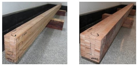
Fig. 1. Structural laminated bamboo
Five groups of specimens were constructed with the same length of 2,400 mm. All specimens were designed with the same depth (100 mm) and span (2,100 mm), with various widths (45, 50, 60, 70, or 80 mm), to determine whether there was any width effect. In addition, the distances between loading support and loading points were the same for all specimens. Each group consisted of four identical specimens. Similar abbreviation was taken for all specimens as can be seen from Table 1. Taking “LBLB80-2” as an example, “LBLB” stands for laminated bamboo lumber beam, and “80” means the width while “2” means the second sample in the group of LBLB80. The cross-sectional structure of the specimens for the first group and fifth group are shown in Fig. 1.
Test Methods
The beams were oriented with the longer side vertical (Fig. 1b) and the test arrangement is illustrated in Fig. 2. The displacement of the two supports, the loading points, and the mid-span deflection were measured by five laser displacement sensors (LDS type: Keyence IL-300, Japan). The beams were strain gauged longitudinally at the middle cross section, with five strain gauges pasted on one side face at even spacing through the depth, and one strain gauge pasted on each of the bottom face and the top face, as shown in Fig. 2. The test was performed using a microcomputer-controlled electro-hydraulic servo testing machine (popwil instrument, Hangzhou, Zhejiang, China) with a capacity of 100 kN and a TDS data acquisition system.
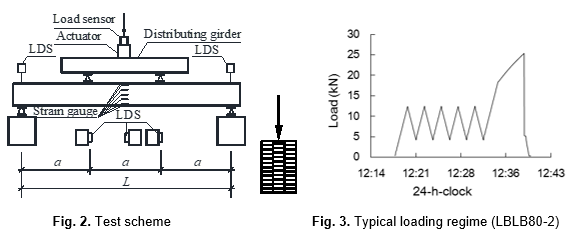
Tests were performed according to ASTM D198 (2010) and GB/T 50329-2012 (2012). The load was applied initially through a load control program. Taking specimen LBLB80-2 as an example, the load was ramped up linearly to 12 kN at a rate of 6 kN/min and then reduced to 4 kN at the same rate. The load was then cycled linearly between 4 kN and 12 kN a total of five times to evaluate the elastic modulus accurately. The load was then increased linearly to 18 kN at the same loading rate, after which the testing process was changed to displacement control. The test continued at a displacement rate of 7 mm/min until the specimen had sustained significant damage, at which time the testing was halted. The variation of load with time for a typical test is shown in Fig. 3.
For bending of the laminated bamboo beams, the modulus of elasticity (MOE) and the modulus of rupture (MOR) were calculated using Eqs. 1 and 2, respectively,
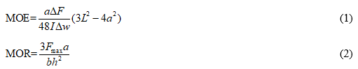
where a is the distance between loading support and loading points; DF is the load increment in the elastic stage; Dw is the deflection of the middle span point under DF; L is the span of the beam; I is the moment of inertia of the beam; Fmax is the maximum bending load; b is the width; and h is the height of the beam cross-section.
RESULTS AND DISCUSSION
Failure Modes and Mechanism Analysis
A typical failure mode can be seen from Fig. 4. Each specimen behaved elastically at the beginning of loading. Load cycling was undertaken in the elastic region. After completion of cycling, with the increase of loading, the specimens showed a small amount of plastic deformation, and the stiffness of the beam decreased markedly. As the deflection became obvious, cracks (accompanied by a slight noise) appeared on the bottom tensile surface, where there were defects such as bamboo joints and mechanical connector parts. Once the bottom-most layer of bamboo fibres separated, the beams split longitudinally and the whole specimen was damaged instantaneously.
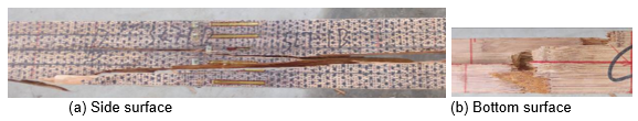
Fig. 4. Failure photos for specimen LBLB70-1
These phenomena are also shown in Fig. 5, in which the load decreased suddenly as soon as the beam split. The beams shed most of the load at this time and could be considered to have failed. All beams failed at the bottom surface and split up the middle through the depth of the beam. Cracks always initiated at the bamboo joint area on the bottom surface. The failure of all specimens was characterised by the brittle tensile failure.
Load – Displacement Response
Figures 5(a) and 5(b) plot the load against displacement for the 45-mm width specimens (group LBLB45) and the 70-mm width specimens (group LBLB70), respectively. For the LBLB45, there was an excellent consistency in the load-displacement response for each of the four specimens. However, there was some scatter in the ultimate failure loads, which ranged from 10.58 to 15.35 kN. The five load cycles between 2 and 5 kN showed so little variation that the cycling was not visible in the graph (all cycles plot over the top of the main elastic loading line). These specimens showed clear elastic behaviour up to a load of approximately 6 kN, followed by non-linear softening behaviour until the specimens failed suddenly and shed most of the load. The load decreased suddenly once the beam split. The specimens do not show any purely plastic behaviour prior to failure, so the failure is relatively brittle in nature.
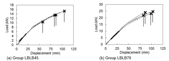
Fig. 5. Load-displacement responses
The load-displacement responses for the four 70-mm width specimens are not quite as consistent as those for the 45-mm specimens (Fig. 5(b)), but the ultimate loads are more consistent, ranging from 21.97 to 24.93 kN. The overall behaviour of the specimens is substantially the same as the 45-mm-wide specimens, with an initial elastic response, followed by non-linear softening and a brittle failure.
The other groups of specimens (50, 60, and 80-mm widths) all displayed similar load-displacement responses to those plotted in Fig. 5. The purpose of testing specimens of different widths was to determine whether there was any size effect present. If there is no width size effect, the load-displacement relationships should be normalised by dividing the load by the width of the beam. Figure 6 plots the normalised load against the displacement for all 20 specimens. Different end markers are used to indicate the specimens from different width groups. All curves overlap with each other, particularly in the elastic stage. This figure shows that there is no evident size effect.
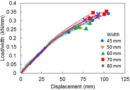
Fig. 6. Normalised load-displacement response for all five groups
Combined Results
The detailed test results for all 20 specimens are presented in Table 1. The average deflection at ultimate load was 85 mm (standard deviation 12 mm), which was far bigger than the maximum allowable design value of 8.4 mm. The serviceability limit state design specified in the Chinese wood structure design specification (GB 50005-2003, 2003) states that the middle deflection should be less than L/250 (where L is the span of the beam). The fifth percentile value for the test deflections was 54.0 mm, which is still 6.43 times the design value of 8.4 mm; however, the safety factors for timber structures are less than 6.43. These results show that both critical design criteria (deflection and strength) can be used as the design criterion for shallow LBL beams. However, the critical design criterion for LBL structures is normally deflection rather than strength. In addition, the advantage of deflection over strength is that it can be measured directly on the beam. Consequently, the bending of modulus of elasticity is of interest. From another point of view, the stiffness of the beam needs to be improved to reduce the deflection and to make full use of the strength.
Based on all 20 specimens, the mean pure bending modulus of elasticity was 10,912 MPa, with a standard deviation of 739 MPa and a coefficient of variation of 6.8%; the modulus of rupture was 63.95 MPa, with a standard deviation of 7.18 MPa and a coefficient of variation of 11.2%. The critical design criterion for LBL structures is often deflection rather than strength, and for design purposes, the characteristic elastic modulus should be used, rather than the mean. Based on the mean and standard deviation quoted, the characteristic elastic modulus for these specimens is 9,696 MPa. This is the value expected to be exceeded by 95% of specimens and was calculated using Eq. 3,
![]() (3)
(3)
where is the characteristic elastic modulus; is the average value; and is the coefficient of variation (COV).
Table 1. Test Results
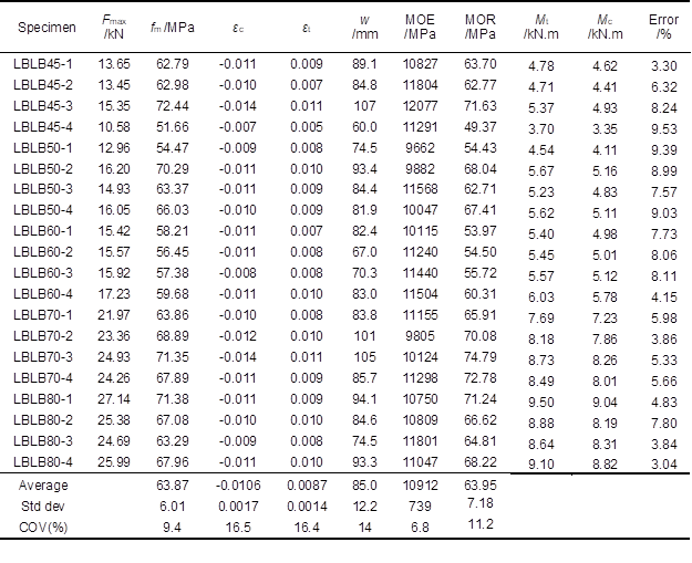
Note: fm is the bending strength; ɛc is the compressive strain at failure; ɛt is the tensile strain at failure; w is the deflection at failure; Mt is the test value; Mc is the calculation value; error (%) is calculated as (Mt–Mc)*100/ Mt
Previous studies on the behaviour of LBL in bending (conducted on smaller specimens) have reported a wide range of ultimate bending strengths, ranging from 67.7 MPa (Lee et al. 1998) to 133 MPa (Ahmad and Kamke 2011). These values are calculated by assuming that the strain distribution across the beam remains linear up until failure (and hence that ultimate moment = bending strength * moment of inertia / max distance from neutral axis). Based on these 20 specimens, the mean ultimate bending strength is 63.9 MPa, with a standard deviation of 6.0 MPa and a COV of 0.09, giving a characteristic bending strength of 54 MPa.
Strain Variation across the Cross-Section
The large specimens used in this study allowed measurements of the strains across the center of the cross-section of the beams throughout the loading process. As mentioned above, previous studies have assumed that the strain distribution across the cross-section remains linear up until failure. However, the results in Table 1 show that the average tensile strain on the bottom of the beams at failure was 0.0087, while the average compressive strain value at the top of the beams at failure was 0.0106. There was no dependence on the width of the specimen. This is a significant difference and suggests that laminated bamboo behaves differently in tension and compression at higher strains.
Figure 7 plots the load against the top and bottom strain at the mid-span cross-section for two typical specimens. These figures show that the initial elastic moduli for both compression and tension are equal. However, the compressive strain deviated from the initial elastic slope sooner than the tensile strain.
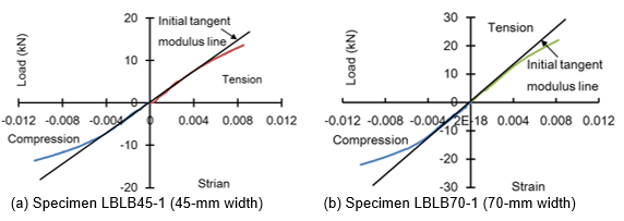
Fig. 7. Typical load-strain curves for the mid-span cross-section
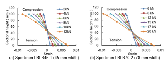
Fig. 8. Typical strain profile development for the mid-span cross-section
Figure 8 plots the evolution of the strain profile through the loading for the mid-span cross-section of the same two typical specimens.
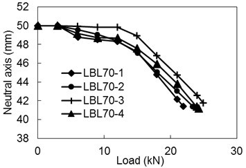
Fig. 9. Descent of neutral axis during loading process (typical)
Each test shows that the strain across the cross-section of the laminated bamboo beam was basically linear throughout the loading process, following standard beam theory. However, over the course of the loading process, the neutral axis moved downwards from the center of the beam, particularly during the latter part of the process.
Figure 9 plots the depth of the neutral axis against the load for the 70-mm width specimens. This figure shows that the descent of the neutral axis coincided with the onset of non-linear deformation observed in the load-displacement diagrams (Fig. 5(b). The other groups of specimens demonstrated the same behaviour. When the applied load reached the elastic limit, the fibres in the compression area entered the plastic state gradually and the compression elastic modulus decreased, leading to the internal force redistribution of the cross-section. Thus, the neutral axis descended to achieve a new equilibrium.
Constitutive Behaviour and Proposed Model
For the cross section to remain in equilibrium as the load increases, the larger strain triangle on the compression side of the beam must result in the same net resultant force as the smaller strain triangle on the tension side of the beam. This can only occur if the modulus of elasticity for the material in compression decreases relative to the material in tension. Previous work by the authors (Li et al. 2013, 2015) has shown that the same structural LBL in pure compression starts to be non-linear at approximately 32 MPa and becomes fully plastic at a strain of approximately 0.02, which was significantly higher than any of the compressive strains measured in the current tests. Tensile tests indicated that the tensile stress has a linear relationship with the strain from the beginning until failure, so the material behaves in an elastic-brittle fashion.
From these observations, a hypothesis can be made that, under bending, the LBL in compression behaves in a similar way to when it is under pure compression, being non-linear at approximately 32 MPa and becoming fully plastic at a strain of 0.02. However, similar to the tensile test results, there was no non-linear under tension, and the material behaves in an elastic-brittle fashion, retaining the same modulus of elasticity up until rupture.
Based on the elastic modulus and ultimate tension at failure identified by the tests reported here, together with the information presented by Li et al. (2013, 2015) for LBL under pure compression, as well as the tensile test results, a model for the stress-strain behaviour of the test structural LBL under bending is proposed in Fig. 10(a).
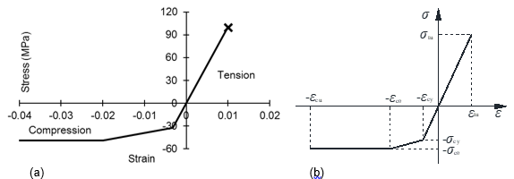
Fig. 10. Proposed model for the stress-strain behaviour of the tested LBL under bending
An initial elastic modulus of 10 GPa is used for both tension and compression. At a compressive stress of 32 MPa, this becomes transformed to a tangent elastic modulus of 1 GPa (compression only), up until a compressive strain of 0.02 (20,000 m), after which the material is assumed to be fully plastic in compression. The elastic modulus of 10 GPa is used for tension until rupture occurs at a strain of 0.01 (10,000 m), which indicates a rupture stress of 100 MPa. For design purposes, the ultimate strain should be reduced to the characteristic value of 0.0077 (7,700 m), and the rupture stress to 77 MPa.
On the basis of the test results and numerical analysis, the universal model figure can be seen from Fig. 10(b), and the analytical expressions of the stress-strain model can be given as the following equations.
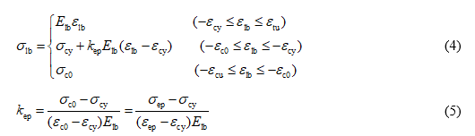
where slb is the stress value of the laminated structural bamboo; Elb is the modulus of elasticity; elb is the strain value of the laminated structural bamboo; ecy is the strain for the yield point; etu is the ultimate tensile strain value; scy is the compression yield stress value; kep is the ratio of the elastic-plastic slope and the modulus of elasticity; sep is the compression stress value for the elastic-plastic stage; eep is the compression strain value for the elastic-plastic stage; ec0 is the compression peak strain value; sc0 is the compression peak stress value; and ecu is the ultimate compression strain value.
Figure 11 shows that the model adequately captures the descent of the neutral axis measured during the experiments. This figure shows the behaviour of the neutral axis for all tests plotted against normalised load (i.e., load/width). As this behaviour is derived from strain plots such as Fig. 8, there was some variation between tests. However, the model represents the typical behaviour very well. Figures 12(a) and (b) show that the non-linear relationship between load and compressive and tensile strains at the top and the bottom of the beam is also well represented. In these figures, the thicker line represents the model results and the thinner lines are the experimental results.
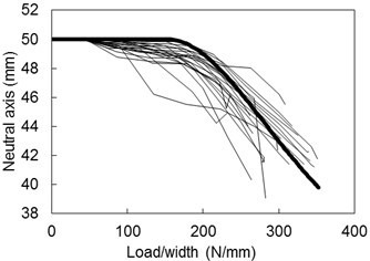
Fig. 11. Descent of neutral axis with load predicted by the new model (heavy line) vs. experimental findings (light lines)
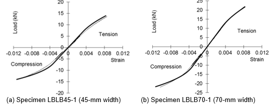
Fig. 12. Development of extreme fibre strains with load predicted by the new model
Finally, Fig. 13 shows that the model reproduced the normalised load-displacement behaviour of the entire test specimen group very well. The thick black line represents the results of the model, and the experimental results are shown in grey for all tests. The close agreement between the model and experimental results supports the hypothesised behaviour of the LBL in bending, wherein under tension the material remains linear elastic until rupturing in a brittle manner, while under compression the material softens and deforms plastically.
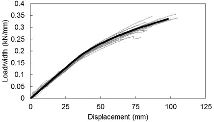
Fig. 13. Normalised load-displacement response predicted by the new model
Calculation of Bending Capacity
As can be seen from Table 1, all the ultimate compression strain values for the beams obtained from the compression tests are smaller than 0.023 but larger than 0.00413, and all the ultimate tensile strain values for the beams obtained from the tensile tests are smaller than 0.0126. These results indicated that the compression area was in the elastic-plastic stage when the beams failed. The strain-stress distribution for the middle cross-section at the ultimate failure state can be expressed as Fig. 14. Several fundamental hypotheses were adopted to establish the calculation formula for the bending capacity. First, there was no extrusion between the transverse fibres for the beams, no scaling along the horizontal direction, and the yield condition for the beams only contains the normal stress sx. Second, the plane cross-section assumption has been proved by the experiments. Thirdly, the small transmogrification assumption can still be used for the beams tested.
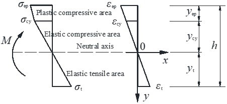
Fig. 14. Strain-stress distribution at the ultimate failure state
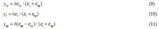
As can be seen from Fig. 14, the relationship between the heights for different parts can be expressed as follows:
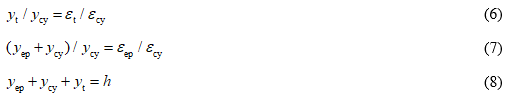
From Eqs. 6 to 8, the following formulas can be obtained:
The ultimate bending moment for the simply supported LBL beams can be expressed as follows:
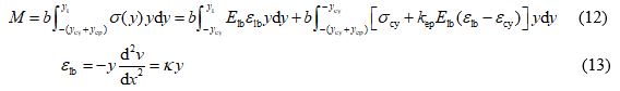
where is the curvature and is the width of the beam cross-section.
The final calculation formula for the ultimate bending moment can be obtained by substituting Eqs. 6 to 11 and 13 into Eq. 12, that is,
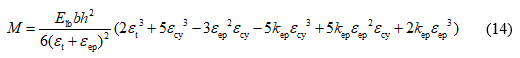
The comparison between the test results and calculation results can be seen in Table 1.
CONCLUSIONS
To investigate the bending properties of LBL, 20 beam tests were performed. Based on analysis of the test data, the following conclusions can be drawn.
- The failure of LBL beams is characterised by brittle tensile failure initiated at the tension face of the beam. The tensile strength of the bamboo is sensitive to the stress concentrations occurring in areas with defects.
- The beams behave elastically until approximately half the ultimate load, and the elastic moduli for compression and for tension of the LBL are equal. The strain across the cross-section of the LBL beam is linear throughout the testing process, following standard beam theory. There are no obvious width effects on the ultimate tensile strain, bending strength, and elastic modulus of the LBL beam.
- The critical design criteria for LBL structures is normally deflection rather than strength. From another point of view, the stiffness of the beam needs to be improved to reduce the deflection and to make full use of the strength.
- A simple tri-linear model of this behaviour, in which the compressive tangent modulus of elasticity is reduced to 10% of the initial value once a compressive stress of 32 MPa is reached, has been shown to represent the observed strain and displacement behaviour of the beams very well. A universal model was also proposed, and a calculation formula for the ultimate bending moment was proposed.
ACKNOWLEDGMENTS
The material presented in this paper was based on work supported by the National Natural Science Foundation of China (51308301), the Natural Science Foundation of Jiang-su Province (BK20130978), the China Postdoctoral Science Foundation (2015M580382), Jiangsu Postdoctoral Science Foundation Project (1501037A), and a Project Funded by the Priority Academic Program Development of Jiangsu Higher Education Institutions. Any opinions, findings, and conclusions or recommendations expressed in this material are those of the writer(s) and do not necessarily reflect the views of the foundations. The writers gratefully acknowledge Nian-qiang Zhou, Chen Lu, Qiang Kong, Cheng Tan, Ying Xu, Jing Lu, Fan Wu, Ling-fei Zhang, Xiu-yu Chen, Zhao Song, and others from the Nanjing Forestry University for helping with the tests.
REFERENCES CITED
ASTM D198 (2010). “Standard test methods for static tests of lumber in structural sizes,” ASTM International, West Conshohocken, PA.
Bohannan, B. (1962). “Pre-stressed wood members,” Forest Products Journal 12(12), 596-602.
Correal, J. F., and Ramirez, F. (2010). “Adhesive bond performance in glue line shear and bending for glued laminated guadua bamboo,” Journal of Tropical Forest Science 22(4), 433-439.
Chen, G., Li, H. T., Zhou T., LI C. L. (2015). “Experimental evaluation on mechanical performance of OSB webbed parallel strand bamboo I-Joist with holes in the web,” Construction and Building Materials 101, 91-98. DOI:10.1016/j.conbuildmat.2015.10.041
De Flander, K., and Rovers, R. (2009). “One laminated bamboo-frame house per hectare per year,” Construction and Building Materials 23(1), 210-218. DOI: 10.1016/j.conbuildmat.2008.01.004
GB 50005-2003 (2003). “Chinese wood structure design specification,” China Architecture and Building Press, Beijing.
GB/T 50329-2012 (2012). “Standard for test methods of timber structures,” China Architecture and Building Press, Beijing.
Lakkad, S. C., and Patel, J. M. (1980). “Mechanical properties of bamboo, a natural composite,” Fiber Science and Technology 14, 319-322.
Lee, C. H., Chung, M. J., Lin, C. H., and Yang, T. H. (2012). “Effects of layered structure on the physical and mechanical properties of laminated moso bamboo (Phyllostachys edulis) flooring,” Construction and Building Materials 28(1), 31-35. DOI: 10.1016/j.conbuildmat.2011.08.038
Lee, A. W. C., Bai, X. S., and Bangi, A. P. (1998). “Selected properties of laboratory-made laminated-bamboo lumber,” Holzforschung 52(2), 207-210. DOI: 10.1515/hfsg.1998.52.2.207
Li, H. T., Zhang, Q. S., and Wu G. (2015). “Stress-strain model under compression for side pressure laminated bamboo,” Journal of Southeast University (Natural Science) 45(6), 1130-1134.
Li, H. T., Su, J. W., Deeks A. J., Zhang, Q. S., Wei, D. D., and Yuan, C. G. (2015). “Eccentric compression performance of parallel bamboo strand lumber column,” BioResources 10(4), 7065-7080. DOI: 10.15376/biores.10.4.7065-7080
Li, H. T., Zhang, Q. S., Huang, D. S., and Deeks, A. J. (2013). “Compressive performance of laminated bamboo,” Composites Part B: Engineering 54, 319-328. DOI: 10.1016/j.compositesb.2013.05.035
Li, H. T., Su, J. W., Zhang, Q. S., and Chen, G. (2015). “Experimental study on mechanical performance of side pressure laminated bamboo beam,” Journal of Building Structures 36(3), 121-126.
Li, H. T., Su, J. W., Zhang, Q. S., Deeks, A. J., and Hui, D. (2015). “Mechanical performance of laminated bamboo column under axial compression,” Composites Part B: Engineering 79, 374-382. DOI: 10.1016/j.compositesb.2015.04.027
Li, H. T., Su, J. W., Wei, D. D., Zhang, Q. S., and Chen G. (2015). “Comparison study on parallel bamboo strand lumber under axial compression for different directions based on the large scale,” Journal of Zhengzhou University (Engineering Science) 36(5), 31-36.
Lopez, L. F., and Correal, J. F. (2009). “Exploratory study of the glued laminated bamboo Guadua angustifolia as a structural material,” Maderas-Ciencia y Tecnologia 11(3), 171-182.
Mahdavi, M., Clouston, P. L., and Arwade, S. R. (2011). “Development of laminated bamboo lumber: Review of processing, performance, and economical considerations,” Journal of Materials in Civil Engineering 23(7), 1036-1042. DOI: 10.1061/(ASCE)MT.1943-5533 .0000253
Nugroho, N., and Ando, N. (2001). “Development of structural composite products made from bamboo. II. Fundamental properties of laminated bamboo lumber,” Journal of Wood Science 47(3), 237-242. DOI: 10.1007/BF01171228
Paes, J. B., Freire de Oliveira, A. K., and de Oliveira, E. (2009). “Physical-mechanical characterization of the glue laminated bamboo (Dendrocalamus giganteus),” Ciencia Florestal 19(1-2), 41-51.
Rassiah, K., Ahmad, M. M. H. M., and Ali, A. (2014). “Mechanical properties of laminated bamboo strips from Gigantochloa scortechinii/polyester composites,” Materials and Design 57, 551-559. DOI: 10.1016/j.matdes.2013.12.070
Sulastiningsih, I. M., and Nurwati (2009). “Physical and mechanical properties of laminated bamboo board,” Journal of Tropical Forest Science 21(3), 246-251.
Sulaiman, O., Hashim, R., and Wahab, R. (2006). “Evaluation of shear strength of oil treated laminated bamboo,” Bioresource Technology 97(18), 2466-2469. DOI: 10.1016/j.biortech.2005.10.026
Sinha, A., Way, D., and Mlasko, S. (2014). “Structural performance of glued laminated bamboo beams,” Journal of Structural Engineering 140(1), 04013021. DOI: 10.1061/(ASCE)ST.1943-541X.0000807
Su, J. W., Li, H. T., Yang, P, Zhang, Q. S., and Chen, G. (2015a). “Mechanical performance study on laminated bamboo lumber column pier under axial compression,” China Forestry Science and Technology 29(5), 89-93.
Su, J. W., Wu F., Li, H. T., and Yang P. (2015b). “Experimental research on parallel bamboo strand lumber column under axial compression,” China Sciencepaper 10(1), 39-41.
Verma, C. S., and Chariar, V. M. (2012). “Development of layered laminate bamboo composite and their mechanical properties,” Composites Part B-Engineering 43(3), 1063-1069. DOI: 10.1016/j.compositesb.2011.11.065
Weibull (1951). “A statistical distribution function of wide application,” Journal of Applied Mechanics 9, 293-297.
Wei, Y., Jiang, S. X., Lv, Q. F., Zhang, Q. S., Wang, L. B., and Lv, Z. T. (2011). “Flexural performance of glued laminated bamboo beams,” Advanced Materials Research 168-170, 1700-1703. DOI: 10.4028/www.scientific.net/AMR.168-170.1700
Yeh, M. C., and Lin, Y. L. (2012). “Finger joint performance of structural laminated bamboo member,” Journal of Wood Science 58(2), 120-127. DOI 10.1007/s10086-011-1233-7
Xiao,Y., Chen, G., and Feng, L. (2014). “Experimental studies on roof trusses made of glubam,” Materials and Structures 47(11), 1879-1890
Article submitted: August 3, 2015; Peer review completed: November 7, 2015; Revised version received and accepted: November 10, 2015; Published: December 3, 2015.
DOI: 10.15376/biores.11.1.929-943